Beijer Electronics X2 control User manual


Foreword
Installation manual for X2 base 5 v2
Foreword
All operator panels are developed to satisfy the demands of human-machine
communication. Built-in functions such as displaying and controlling text,
dynamic indication, time channels, alarm and recipe handling are included.
The operator panel works primarily in an object-oriented way, making it easy to
understand and use. Configuration is carried out on a PC using iX Developer
software. The project can then be transferred and stored in the operator panel
itself.
Various types of automation equipment such as PLCs, servos or drives can be
connected to the operator panels. In this manual, the term “the controller” refers
to the connected equipment.
This manual explains how to install the operator panel. Please refer to the
iX Developer reference manual for further information.
Order no: MAEN328
Copyright © 2021-05 Beijer Electronics AB. All rights reserved.
The information in this document is subject to changewithoutnoticeandisprovidedasavailableatthe
time of printing. Beijer Electronics AB, including all its group companies, reserves the right to change any
information without updating this publication. Beijer Electronics AB, including all its group companies,
assumesnoresponsibilityforanyerrorsthatmayappearinthisdocument. Readtheentireinstallation
manual prior to installing and using this equipment. Only qualified personnel may install, operate or repair
this equipment. Beijer Electronics AB, including all its group companies, are not responsible for modified,
altered or renovated equipment. Because the equipment has a wide range of applications, users must acquire
the appropriate knowledge to use the equipment properly in their specific applications. Persons responsible
for the application and the equipment must themselves ensure that each application is in compliance with
all relevant requirements, standards and legislationinrespecttoconfigurationandsafety. Onlypartsand
accessories manufactured according to specifications set by Beijer Electronics AB, including all its group
companies, may be used.
BEIJER ELECTRONICS AB, INCLUDING ALL ITS GROUP
COMPANIES, SHALL NOT BE LIABLE TO ANYONE FOR ANY
DIRECT, INDIRECT, SPECIAL, INCIDENTAL OR CONSEQUENTIAL
DAMAGES RESULTING FROM THE INSTALLATION, USE OR
REPAIR OF THIS EQUIPMENT, WHETHER ARISING IN TORT,
CONTRACT, OR OTHERWISE. BUYER'S SOLE REMEDY SHALL
BE THE REPAIR, REPLACEMENT, OR REFUND OF PURCHASE
PRICE, AND THE CHOICE OF THE APPLICABLE REMEDY SHALL
BE AT THE SOLE DISCRETION OF BEIJER ELECTRONICS AB,
INCLUDING ALL ITS GROUP COMPANIES.
Beijer Electronics, MAEN328

Contents
Contents
1 SafetyPrecautions ....................................................... 4
1.1 General ........................................................... 4
1.2 Hazardous Materials ............................................. 4
1.3 DisposalRequirementsUnderWEEERegulations ........... 5
1.4 DuringInstallation .............................................. 5
1.5 DuringUse ....................................................... 5
1.6 Service and Maintenance ........................................ 5
1.6.1 CleaningtheDisplay ............................................ 5
1.7 Dismantling and Scrapping ..................................... 6
1.8 Appearance of Air in Touch Screen ............................. 6
2 NamingConvention .................................................... 7
3 Installation ............................................................... 8
3.1 SpaceRequirements ............................................. 8
3.2 InstallationProcess .............................................. 8
3.2.1 ConnectionstotheController ..................................10
3.2.2 OtherConnectionsandPeripherals .............................10
3.2.3 OpenPorts .......................................................10
4 TechnicalData ........................................................... 11
5 ChemicalResistance .................................................... 13
5.1 Touch Screen and Overlay Material ............................ 13
5.1.1 ProtectiveFilm ...................................................13
5.1.2 TouchScreenSurface ............................................14
5.1.3 TouchScreenProtector ..........................................14
6 OperatorPanelDrawings .............................................. 15
6.1 Connectors ....................................................... 15
6.2 X2base5v2Outline ............................................. 17
7 Additional Installation Tips ............................................ 18
7.1 Grounding the operator panel .................................. 18
7.2 EthernetConnectionintheOperatorPanel ................... 19
7.3 To Achieve Better EMC Protection ............................. 20
7.4 AmbientTemperature ........................................... 21
7.5 Safety ............................................................. 23
7.6 GalvanicIsolation ................................................ 24
7.7 Cable and Bus Termination RS-485 ............................ 26
7.8 USBMemorystick ............................................... 26
Beijer Electronics, MAEN328

Safety Precautions
1SafetyPrecautions
Both the installer and the owner and/or operator of the operator panel must read
and understand this installation manual.
1.1 General
•Read the safety precautions carefully.
•Check the delivery for transportation damage. If damage is found, notify the
supplier as soon as possible.
•Do not use the operator panel in an environment with high explosive hazards.
•The supplier is not responsible for modified, altered or reconstructed
equipment.
•Use only parts and accessories manufactured according to specifications of
the supplier.
•Read the installation and operating instructions carefully before installing,
using or repairing the operator panel.
•Neverallowfluids,metalfilingsorwiringdebristoenteranyopeningsinthe
operator panel. This may cause fire or electrical shock.
•Only qualified personnel may operate the operator panel.
•Storing the operator panel where the temperature is lower/higher than
recommended in this manual can cause the LCD display liquid to
congeal/become isotropic.
•The LCD display liquid contains a powerful irritant. In case of skin contact,
wash immediately with plenty of water. In case of eye contact, hold the eye
open,flushwithplentyofwaterandgetmedicalattention.
•Thefiguresinthismanualserveanillustrativepurpose. Becauseofthemany
variables associated with any particular installation, the supplier cannot
assume responsibility for actual use based on the figures.
•The supplier neither guarantees that the operator panel is suitable for your
particular application, nor assumes responsibility for your product design,
installation or operation.
•It is recommended to turn on and shut down the operator panel at least once
before installing any components/cards or before connecting the operator
panel to external devices; for example serial devices.
•For Marine panels only:
–The operator panel must be installed and operated as described in this
document to meet this certification.
–Observe precautions for handling electrostatic discharge sensitive devices
1.2 HazardousMaterials
Toxic and hazardousmaterialsor elements
有毒和有害的材料或元素
Part description
零件描述
Pb Hg Cd Cr6+ PBB PBDE
PCBand elect ronic
component s
PCB和电子元件
XOO O O O
Beijer Electronics, MAEN328 4

Safety Precautions
1.3 Disposal RequirementsUnder
WEEERegulations
For professional users in the European Union: If you wish to discard electrical
and electronic equipment (EEE), please contact your dealer or supplier for further
information.
For disposal in countries outside of the European Union: If you wish to discard
this product please contact your local authorities or dealer and ask for the correct
method of disposal.
1.4 DuringInstallation
•Install the operator panel according to the accompanying installation
instructions.
•Ground the operator panel according to the accompanying installation
instructions.
•Only qualified personnel may install the operator panel.
•Separate the high voltage, signal, and supply cables.
•Make sure that the voltage and polarity of the power source is correct before
connecting the operator panel to the power outlet.
•Peripheral equipment must be appropriate for the application and location.
1.5 DuringUse
•Keep the operator panel clean.
•Emergency stop and other safety functions may not be controlled from the
operator panel.
•Do not use excessive force or sharp objects when operating the touch screen.
1.6 Service and Maintenance
•Only qualified personnel should carry out repairs.
•The agreed warranty applies.
•Before carrying out any cleaning or maintenance operations, disconnect the
equipment from the electrical supply.
•Clean the display and surrounding front cover with a soft cloth and mild
detergent.
1.6.1 Cleaningthe Display
We recommend using a dry, clean cloth to wipe off dust regularly. Use alcohol or
ammonia-based cleaning agent for cleaning only when necessary. When other
solvents or cleaning agents are used, be sure to follow manufacturers’ instructions.
The agent should be applied to a clean cloth and should not be sprayed directly
onto the panel surface. After cleaning the agent should be removed.
Ammonia based glass cleaners (typically 5-10% ammonia) or 75% alcohol can be
used to clean the surface of PCAP and resistive touch panels.
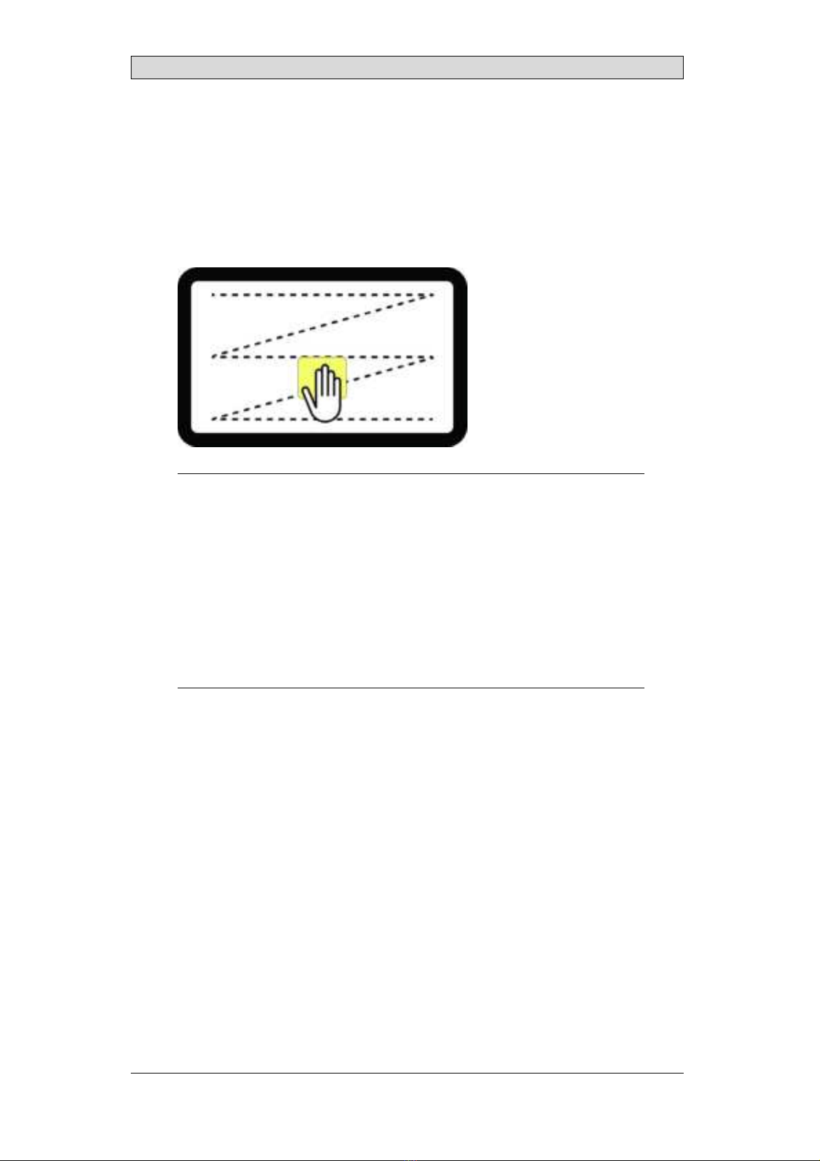
When you clean the surface of your touch panel, please follow these steps:
Beijer Electronics, MAEN328 5
Safety Precautions
1. Apply cleaning agent (alcohol, bleach, or glass cleaner) to a clean cloth. Make
sure the cloth is well saturated.
2. Wipe touch panel in a “Z” motion on the touch panel surface.
3. Dry the panel thoroughly with a dry cloth, removing as much of the cleaning
solution as possible.
4. Do not mix bleach and ammonia because this will produce a dangerous
chemical reaction.
5. Please do not spray cleaning solution directly onto the touch panel surface.
Note:
•Cleaning solut ions cont aining bleach, alcohol, and ammonia are cor rosive t o
t ouch panel sur face coat ingsand ITOfil m. So, you shoul d not leave t he sol ut ion on
t he t ouch panel surface f or more t han 2 minut es. Make sure t o remove all residue
when finished cleaning.
•Do not use sharp t oolst o clean t he surf ace of t he t ouchscreen.
•Do not use air guns, wat er j et s, or st eam, t o clean t he surf ace of t ouchscreens as
t hey may damage t ouchscreen f unct ional it y.
•If condiment s, food, or drinksare spil led on t he surf ace of t he t ouchscreen, please
remove t hem immediat ely.
•Ensure moist ure doesnot seep t hrough t he cabl e connect i on ar ea f r om t he edges
during cleaning.
1.7 Dismantlingand Scrapping
•The operator panel or parts thereof shall be recycled according to local
regulations.
•The following components contain substances that might be hazardous to
health and the environment: lithium battery, electrolytic capacitor, and
display.
1.8 Appearance of Air in Touch Screen
The layer structure of the touch screen contains air. In rare cases, the appearance
of bubbles can arise. This is purely cosmetic and does not affect the functionality
of the operator panel. The appearance can occur under certain environmental
conditions such as temperature, humidity, and atmospheric pressure.
Beijer Electronics, MAEN328 6

Naming Convention
2 NamingConvention
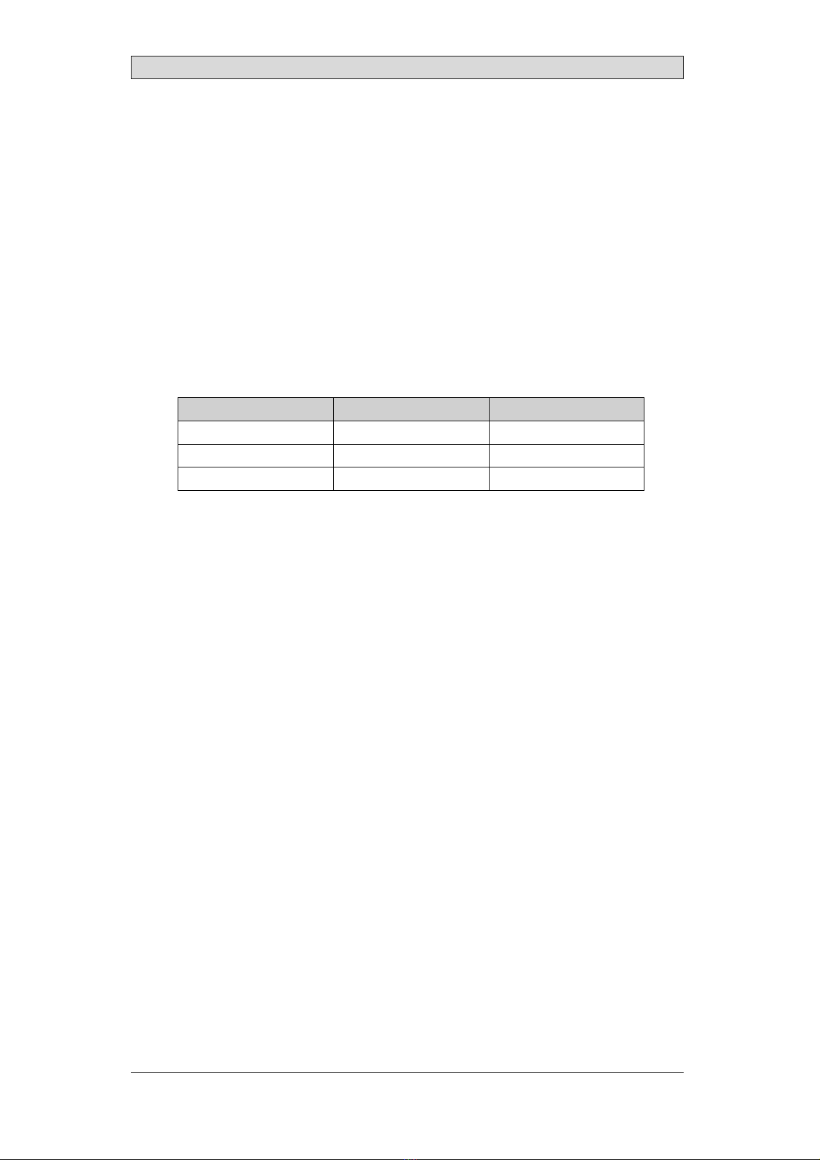
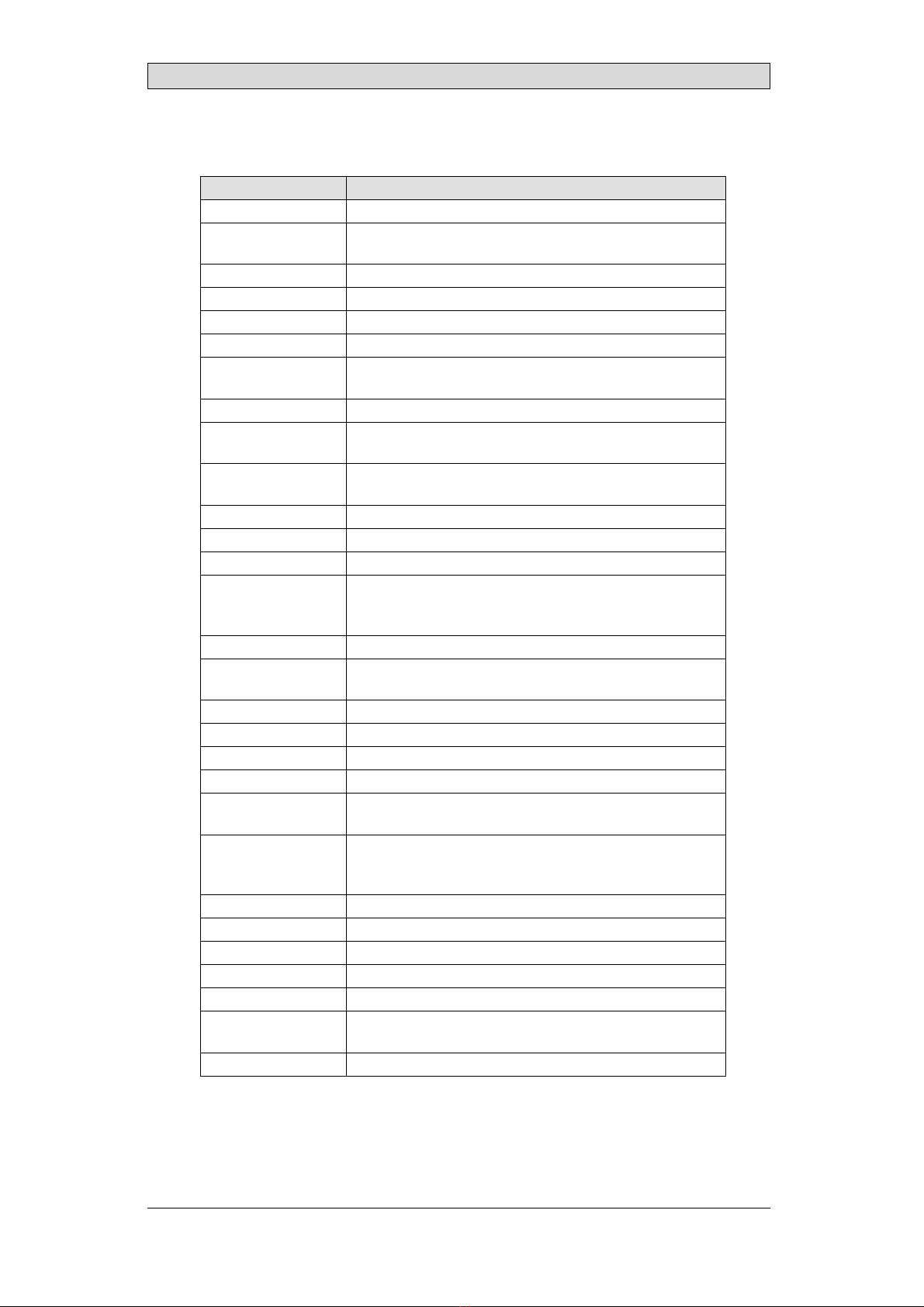
The name of each panel is based on its properties according to the table below.
X2 family Size (inches)
Genera-
tion/ Version Variant
base
pro
marine (= wit h
BL)
cont r ol (= wit h
SC)
mot i on (= wit h
SM)
ext reme
4
5
7
10
12
15
21
v2 SC
SM
HB
HP
BL
12V
SL
RO
CO
web
Soft Cont rol
Soft Mot ion
High Bright ness
High perf ormance
Black
12 Volt
Sealed
Rugged Only
Cer t ificat ion Only
Examples:
•X2 base 5 v2
•X2 pro 7
•X2 control 10
•X2 marine 12 SC
•X2 marine 15 HB SC
•X2 extreme 7 12V*
•X2 extreme 12 HP SC*
•X2 extreme 7 SL HP*
•X2 extreme 12 SL HP SC*
•X2 extreme 7 CO*
•X2 extreme 12 SL HP RO
Note:
Not all combinat ionsare available.
Note:
* indicat esvariant sincl uding IECEx\ ATEXand C1D2 accredit at ion.
Beijer Electronics, MAEN328 7

Installation
3Installation
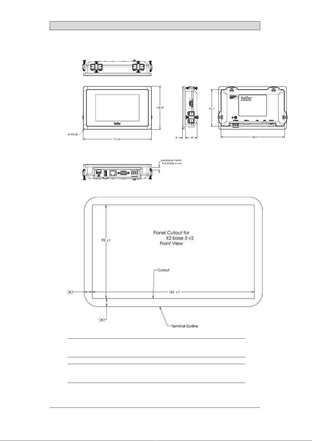
3.1 Space Requirements
•Maximum installation plate thickness: 4 mm.
The following drawings show the space requirements in millimeters when
installing the operator panel. The drawings are only illustrative and may be out of
proportion.
100,00
50,00
100,00
50,00
100,00
3.2 Installation Process
The following is needed:
•A Phillips/slot screwdriver
Do the following:
1. Unpack and check the delivery. If damage is found, notify the supplier.
Note:
Place t he operat or panel on a st able surf ace during inst allat ion.
Dropping t he operat or panel or let t ing it f all may cause damage.
2. To cut a correct opening for the operator panel, use the cut out dimensions
in the outline drawing.A separate cut out drawing is available for download
from the Beijer Electronics web site. For more information, see sections
Operator Panel Drawings and Technical Data.
Beijer Electronics, MAEN328 8
Installation
3. Make sure that the mounting surface of the cutout is smooth and cleaned from
any burrs or debris.
4. Install the operator panel into the cutout.
5. In cases where the front panel seal is critical, use a torque wrench to ensure all
screws are torqued within the specification above.
6. Connect the cables in the specified order, according to the drawing and steps
below.
Caution:
•The oper at or panel must be brought t o ambient t emperat ure bef ore it isst art ed
up. If condensat ion f orms, ensure t hat t he operat or panel is dry before connect ing
it t o t he power out l et .
•Ensure t hat t he operat or panel and t he cont roller syst em have t he same elect rical
grounding (ref erence vol t age level), ot herwise errors in communicat ion may
occur.
•Ensure t hat t he volt age and pol arit y of t he power source iscorrect .
•Separat e high volt age cables from signal and supply cables.
•Shielded communicat ion cablesare recommended.
24V DC
RS232/
RS422/
RS485
24V DC
A
D
Controller
Power
B
Ethernet
C
The image is illustrative only and may differ slightly from the actual panel.
–Connect cable A.
–Connect cable B, using 14-20 AWG (2.08–0.52 mm2), 180–220 N-cm
torque.
–Connect cable C.
–Connect cable D. The recommended cross-section of the cable is 1.5
mm2.
7. Carefully remove the protective film over the operator panel display, take care
to avoid static electricity that could damage the panel.
Beijer Electronics, MAEN328 9
Installation
3.2.1 Connectionsto the Controller
For information about the cables to be used when connecting the operator panel to
the controller, please refer to the help file for the driver in question.
3.2.2 Other Connectionsand Peripherals
Cables, peripheral equipment and accessories must be suitable for the application
and its environment. For further details or recommendations, please refer to the
supplier.
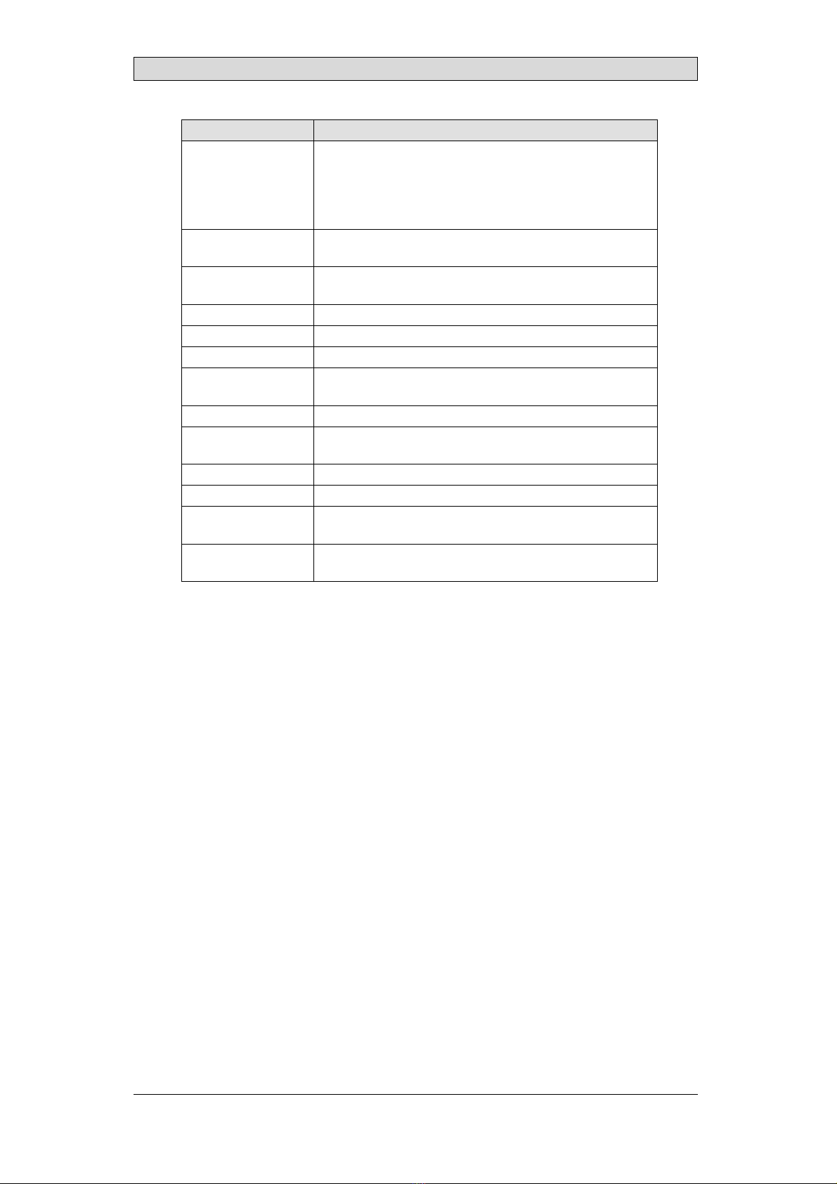
3.2.3 Open Ports
In the firmware there are some ports that are open by default due to the operating
system or that the internal application requires it.
Type Descript ion Open by default
UDP Proj ect t ransf er (9999) Yes
UDP Net bios(137) Yes
UDP Net bi os(138) No(1)
(1) Filt ered.
Beijer Electronics, MAEN328 10
Technical Data
4TechnicalData
Paramete r X2 base 5 v2
Front panel, W×H×D 172x109x37mm
Cut out dimensions,
W×H
161x93 (+/ -1) mm
Mount ing dept h 32 mm (132 mm including cl earance)
Mount ing Swit chboard inst all at ion
Front panel seal IP65
Rear panel seal IP 20
Touch screen
mat erial
Polyest er on glass, ITO film, resist ive
Frame overl ay Aut oflex EBA 180L
Touch screen
operat ions
1 million finger t ouch operat ions
Re ve r se si de
mat erial
Pl ast ic
Frame mat erial Plast ic
Weight 0.32 kg
CPU TI Sit ara AM335x Single Core 600MHz, (TI AM3352BZCZ60)
Seri al por t COM A St andard DSUB (9-pin, f emal e).
1x RS232 RX/ TXwit h RTS/ CTS
1x RS422 or 2x RS485
Serial port COMB N/ A
Serial port COMC 3 pin screw connect or
1x RS485
Et hernet LAN A 10/ 100 Mbit / s. Shielded RJ 45
Et hernet LAN B N/ A
USB-A 1 × USBHost 2. 0, max out put 500 mA
USB-B N/ A
Ext ernal st orage
media
N/ A
Flash memory
(appl icat ion
memory)
2GB
Memory RAM 512 MB(DDR3)
NVRAM N/ A
LED N/ A
Re al t i m e cl ock Yes
Bat t ery Lit hium bat t ery t ype CR2032, exchangeabl e
Pow er con sum pt i on
at rat ed volt age
4.8 W
Fuse Int ernal DCf use, 3 AT, SMD
Beijer Electronics, MAEN328 11
Technical Data
Paramete r X2 base 5 v2
Power supply +24 VDC(18-32 V DC)
CE: The power suppl y must conf orm wit h t he requirement s
according t o EN/ IEC60950 and EN/ IEC61558-2-4.
UL and cUL: The power supply must conf orm wit h t he
requirement s for class2 power supplies.
Di splay 5. 0” TFT-LCDwit h LEDbacklight . 800x480 pixels, 16. 7M
colors
Act ive area of
display, W × H
108. 00 x 64.80
Pixel errors ClassI (ISO9241-307)
Backlight bright ness 250 cd/ m2
Backlight l if et ime 20000 hours
Operat ing
t emperat ure
0°C–+50°C
St orage t emperat ure -20 ° C–+60 ° C
Relat ive humidit y in
operat ion
5 - 90%non-condensed / 25° C
Vibrat ion 1g, according t o IEC60068-2-6, Test Fc
Mechanical shock 10g, half -sine, 6msaccording t o IEC60068-2-27
Approvalsand
cert ificat ions
CE/ FCC
Inf ormat ion isavailable on www.beij erelect ronics.com
UL approval Inf ormat ion isavail abl e on ht t p:/ / www.beij erelect ron-
ics.com and/ or ht t ps:/ / UL.com
Beijer Electronics, MAEN328 12
Chemical Resistance
5 Chemical Resistance
5.1 Touch Screen and Overlay Material
5.1.1 Protective Film
Solvent Resistance
The protective film withstands exposure of more than 24 hours duration under
DIN42115Part2tothefollowingchemicalswithoutvisiblechange:
Acet onit ril e Diesel Pet rol eum spirit (1)
Aj ax / Vim in solut ion Downy / Lenor(1) Phosph or i c ac i d ( <30%)
Alkalicarbonat e
solut ion(1) Et hanol Pot assium ferricyanide
Ammonia (<40%)(1) Glycerine Pot assium hydroxide (<30%)
Acet ic acid (<50%) Glycol Pure Turpent ine
Ariel powder in
solut ion(1) Gumpt ion(1) SBP60/ 95(1)
Bleach(1) Hydrochloric acid (<36%) Sulf uric acid (<10%)
Cast or oil Linseed oil Tomat o ket chup
Caust ic soda (<40%)(1) Met hanol Trichloroacet ic acid (<50%)
Cut t ing oil Nit ric acid (<10%) Whit e Spirit
Cycl ohexanol Paraf finoil Windex
(1)
Di acet one alcohol Persil powder in solut ion(1) Wisk
(1) Ext r emel y f aint gl ossing of t he t ext ur e w asnot ed.
The Autoflex protective film withstands DIN 42 115 Part 2 exposure of up to 1
hour duration to glacial acetic acid without visible change.
The Autoflex protective film is not resistant to high pressure steam at over 100
°C or the following chemicals:
Concent rat ed mineral acids Benzyl alcohol
Concent rat ed caust ic solut ion Met hylene chloride
Beijer Electronics, MAEN328 13

Chemical Resistance
5.1.2 Touch Screen Surface
The touch screen surface on the operator panel withstands exposure to the
following solvents without visible change:
Solvents Time
Acet one 10 minut es
Isopropanol 10 minut es
To l u e n e 5 h o u r s
Thetouchscreensurfaceontheoperatorpanelismadeofpolyesterwithahard
coat to resist scratches and withstand exposure to many solvents without visible
change.
5.1.3 Touch Screen Protector
For harsh environments and exposure to outdoor conditions, it is recommended
to use a protective film to guard the touch screen from damage. This optional part
can be ordered from Beijer Electronics.
Beijer Electronics, MAEN328 14

Operator Panel Drawings
6 Operator Panel Drawings
6.1 Connectors
Pos Connect or Descript ion
1 Ground screw Screw t o connect f unct ional grund
2 Power supply 3-pin screw connect or, +24VDC(18-32V DC)
3 COM-A DSUB(9-pi n, f emal e), seri al communicat i on por t
4 LAN-A RJ 45 (shielded), 10/ 100Mbit
5 USB-A USB2. 0 Host , max out put current 500 mA
6 COM-Cscrew Screw t o connect COM-Ccable shield
7 COM-C 3-pin screw connect or
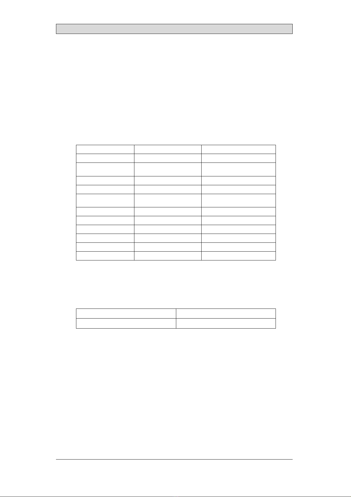
COM-A
Serial port pin assignment
Pin COM1 COM2 COM3
1RS422 TX+ or
RS485 Tx+/ Rx+
2 RS232 RxD
3 RS232 TxD
4 RS422 RX+ RS485 Tx+/ Rx+
5 GND GND GND
6RS422 TX- or
RS485 Tx-/ Rx-
7RS232RTS
8RS232CTS
9 RS422 RX- RS485 Tx+/ Rx-
The connect or support sup t o t hree independent serial communicat ion channel sand
can be configured f or RS-232 and RS-422 or 2×RS-485.
Beijer Electronics, MAEN328 15

Operator Panel Drawings
COM-C
Serial port pin assignment
Pi n COM 6
1GND
2 RS485 Tx+/ Rx+
3 RS485 Tx-/ Rx-
Beijer Electronics, MAEN328 16
Operator Panel Drawings
6.2 X2 base 5 v2 Outline
X2 base 5 v2
Note:
Minimum t hickness f or t he f ront pl at e is 2. 0 mm.
Note:
AStepCADfile is avail able on t he web sit e www. beij erelect ronics.com
Beijer Electronics, MAEN328 17

Additional Installation Tips
7 Additional Installation Tips
When experiencing communication problems in noisy environments or when
operating close to temperature limits, the following recommendations are to be
noticed.
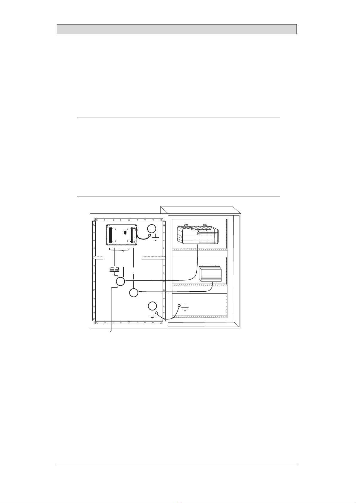
7.1 Groundingthe operator panel
1
2
3
4
5
6
5350
Door
Operator panel
Ferrite core
Mounting plate in the cabinet
Power supply
24 V DC
The mounting clamps of the operator panel do not provide a secure grounding
connection between the panel and the device cabinet, see 1 in drawing above.
1. Connect a wire, that is sized correctly according to local electrical codes,
between the quick-connect terminal connector on the operator panel and the
chassis of the panel, see 2 in drawing above.
2. Connect a wire or grounding braid, that is sized correctly according to local
electrical codes, between the chassis of the operator panel and the closest
grounding point on the door, see 3 in drawing above.
3. Connect a strong but short grounding braid between the door and the device
cabinet, see 4 in drawing above.
4. Twist the cables onto the 24 V DC feed, see 5 in drawing above.
2 turns around the ferrite core provide 4 times the suppression of 1 turn.
3 turns around the ferrite core provide 9 times the suppression of 1 turn.
Connect a wire or grounding braid, that is sized correctly according to local
electrical codes, between the chassis of the operator panel and the closest
grounding point.
Beijer Electronics, MAEN328 18
Additional Installation Tips
Note:
The groundi ng wi resshould be short and t he conduct or should have a l arge ar ea.
A long, t hin grounding wire hasa very high impedance (resist ance) at high frequencies
and does not guide dist urbancest o t he ground.
Mult i-wire conduct orsare bet t er t han singlewireconductorswiththesamearea.
A braided conduct or wire wit h t he same area iseven bet t er. The best isa short , t hick
grounding braid.
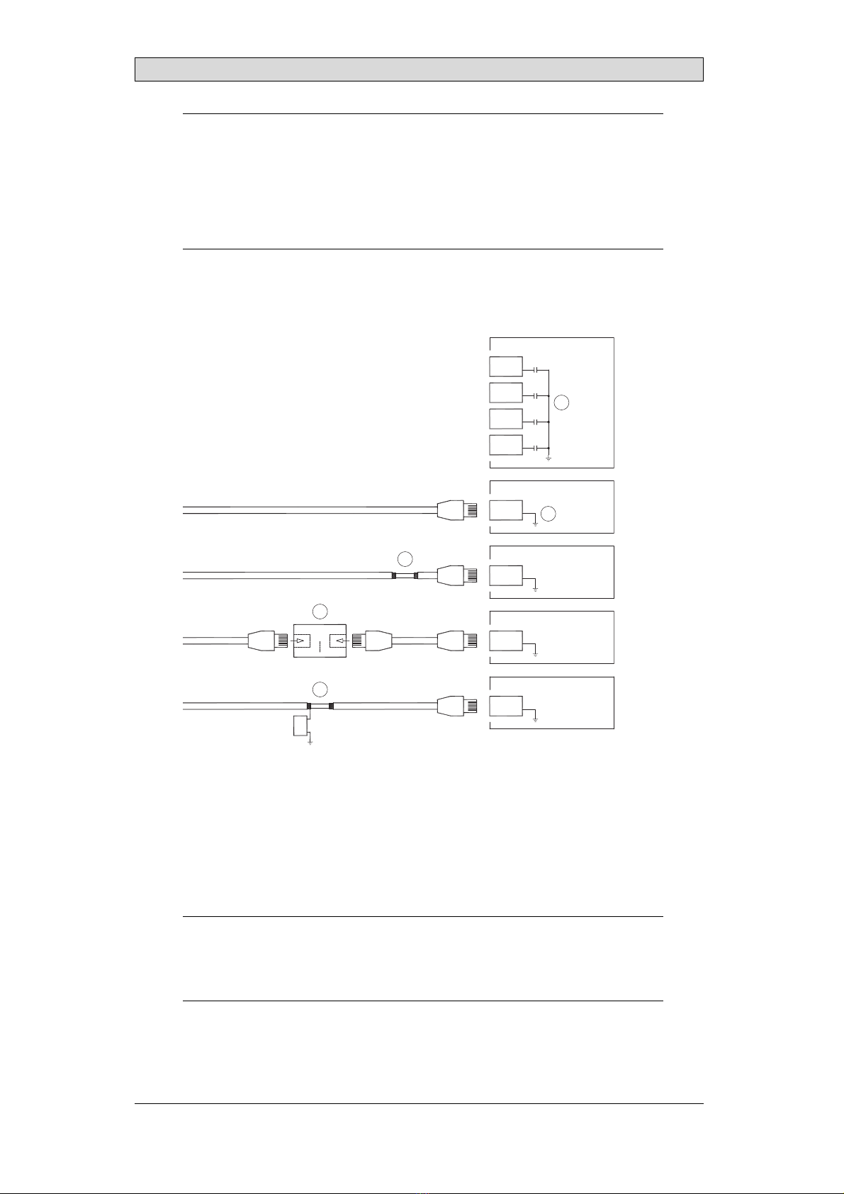
7.2 Ethernet Connection in the
Operator Panel
1
2
3
4
5
RJ45
RJ45
RJ45
RJ45
RJ45
RJ45
RJ45
RJ45
Industrial Ethernet
Operator panel
Operator panel
Operator panel
Operator panel
Shielded
Short and
unshielded
0.1 μF
250 V
1-1
3-3
8-8
2-2
In some industrial units for Ethernet, the RJ45 contact’s shield is connected to the
chassis via a capacitor, see 1 in drawing above.
The operator panel’s Ethernet shield is directly connected to the chassis, see 2 in
drawing above.
1. Check whether the other Ethernet unit has its shield directly grounded or
grounded via a capacitor.
Note:
In many cases, connect ing t he shielded Et hernet cabling t o t he chassisat bot h endsis
inappropriat e. Hum or grounding loopscan occur. Unshiel ded cabling may even result
in f ewer communicat i on errors.
Beijer Electronics, MAEN328 19

Additional Installation Tips
A good solution may be to use a shielded Ethernet cable, but to connect the shield
at one end only.
One option is to break the shield, see 3 in drawing above.
A more elegant method is to expand the shielded Ethernet cabling with a piece of
unshielded Ethernet cable, see 4 in drawing above.
The shield can be grounded via an external 0.1 μF/250 V film capacitor, see 5 in
drawing above. This connects the HF transients to ground.
7.3 To Achieve Better EMCProtection
•Initially, use the original cabling from Beijer Electronics primarily.
•Place the 24 V DC and communications cabling in one cable trunk/cable duct
and 230/380 V AC in another. If the cables need to be crossed, cross them at
90° only. Avoid combining the cabling for stronger 24 V DC outputs with
the communication cabling.
•Initially, use the original cabling from Beijer Electronics primarily.
•Use shielded cables for RS-232 communication.
•Use twisted pair and shielded cabling for RS-422 and RS-485.
•Use the cabling intended for the bus type; Ethernet, Profibus, CC-Link,
CAN, Device Net etc.
•Use the cabling intended for the bus type; Ethernet and CAN
•Install and connect according to applicable specifications for the relevant bus
standard.
•Use shielded cabling for Ethernet, preferably with foil and a braided shield.
•D-sub covers should be shielded, and the shield should be connected to the
cover 360° where the cable enters.
•Connect the shield at both ends.
Shielded cable
Not same potential
Ground plane 1 Ground plane 2
Ground plate Ground plate in another building
0.1 μF/250 V
With longer distances, there is a risk that the ground potential may be different. In
that case, the shield should only be connected at one end. A good alternative is to
connect the other end of the shield to the ground via a 0.1 μF/250 V film capacitor.
Both ends are then connected to the ground in terms of HF, but only connected to
the ground at one end in terms of LF, thus avoiding the 50/60 Hz grounding loops.
Beijer Electronics, MAEN328 20
Other manuals for X2 control
12
Table of contents
Other Beijer Electronics Marine Equipment manuals


Popular Marine Equipment manuals by other brands


Teleflex
Teleflex MV-2 Series owner's manual

Furuno
Furuno Navigational Echo Sounder FE851S Operator's manual

Argus Security
Argus Security SGWS-MOD/865 manual

Kongsberg
Kongsberg EM 2040P Maintenance manual

AUTOHELM
AUTOHELM ST50 Wind Trim Operation and installation

Simrad
Simrad NX40 Installation & operation manual