EPC TOF cam 635 User manual

TOF>cam 635
Installation an Operation Manual
General description
The TOF>cam 635 is a miniaturized and cost-optimized
3D TOF camera. It is based on the E PRO proprietary time-of-
flight (TOF) technology using the epc635 TOF chip. The camera
controls the illumination and the imager chip to obtain distance and
grayscale images.
The cameras are calibrated to provide accurate 3D depth images.
By using the RO driver from E PRO , 3D point clouds in a world
cartesian coordinate system are available.
The depth images are compensated against DRNU errors, modula-
tion errors, ambient-light, temperature and reflectivity of the scene.
Thanks to the high performance of the imager chip with the unique
ambient-light suppression, the camera can be used in many cases
under full sunlight conditions. The output of the TOF>cam 635 is
depth and grayscale images – allowing a variety of new applica-
tions, e.g. for mobile robotics. This module brings you right in front
with the latest technology of 3D depth sensing. All the complex
engineering and time consuming design tasks regarding optics,
illumination and signal processing are already solved.
Features
■Field of view (FOV) of 50° x 19° (h x v)
■Distance measurement ranges on white target:
Wide FOV: 0.1 – 7.5 m, center beam (NFOV): 1.0 – 15 m
■Measurement rate up to 50 TOF measurements per second
■un- and ambient-light tolerant up to 100 kLux
■Calibrated and compensated
■Temperature compensated
■Easy to use
■High speed serial interface UART 10 Mbit/s
■Low power consumption
■RO driver available
■Customized versions possible
Applications
■Distance measurement from centimeters to a few meters
■Mobile robots, automatic vehicle guidance, collision avoidance
■canner for LAM data acquisition in mobile robots
■People and object counting, in-cabin monitoring
■Door opening, machine controlling and safeguarding, IoT
■Gesture control (man-machine-interface)
■Object classification
Figure 1: TOF>cam 635 Figure 2: Wide and narrow field definition
© 2019 E PRO Photonics Corporation
Characteristics subject to change without notice
1 / 39 Installation_and_Operation_Manual_TOF>cam_635-V0.21
www.espros.com

Contents
1. Before you start............................................................................................................................................................. 4
1.1. Precaution and afety...............................................................................................................................................................................4
1.2. Updates.....................................................................................................................................................................................................4
1.3. Important Notes........................................................................................................................................................................................4
. Abbreviations................................................................................................................................................................. 5
3. Technical data................................................................................................................................................................ 6
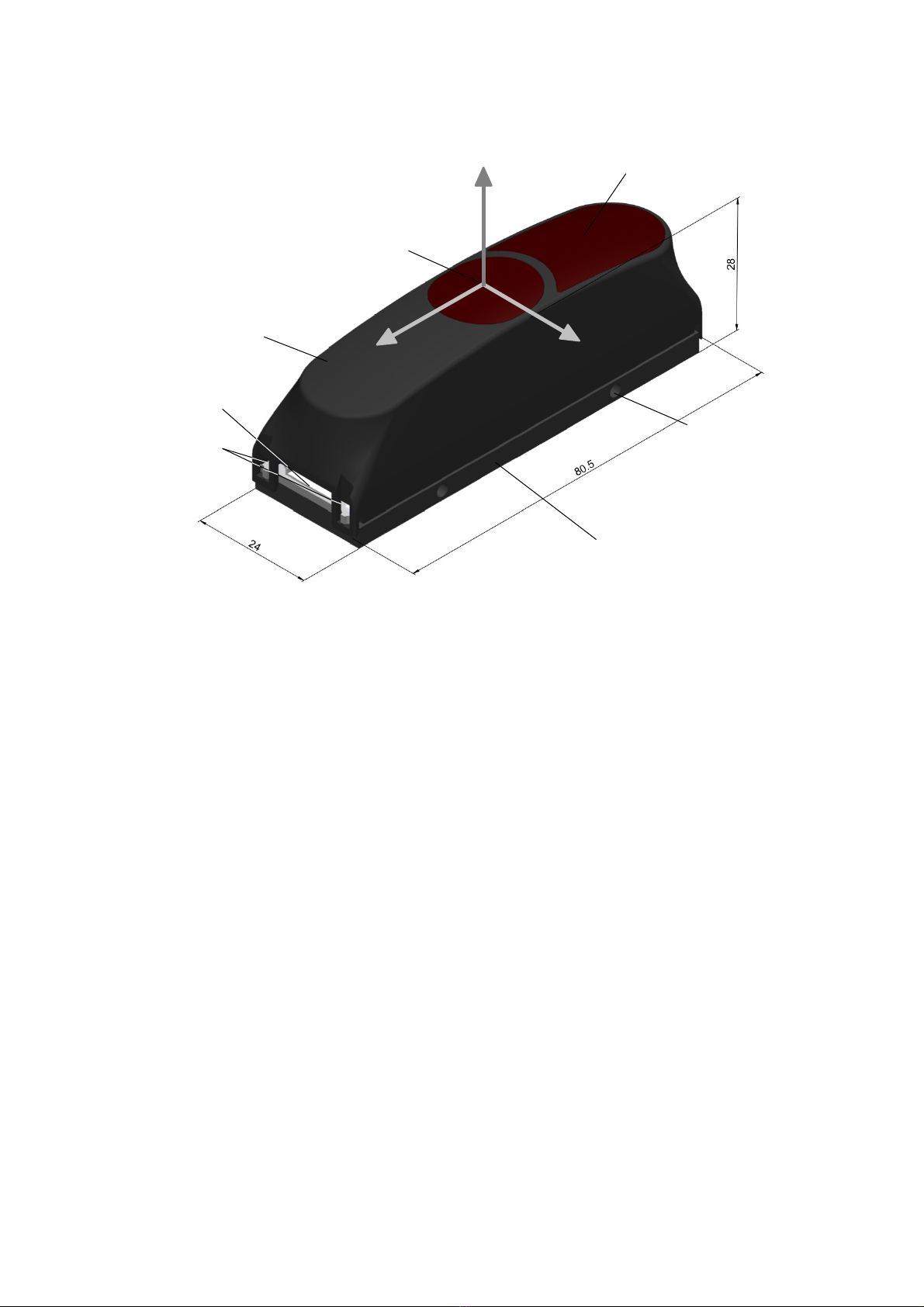
4. Mechanical dimensions................................................................................................................................................7
5. Sensor interface............................................................................................................................................................. 8
5.1. Connector..................................................................................................................................................................................................8
5.2. Pin table....................................................................................................................................................................................................8
6. Power up......................................................................................................................................................................... 9
7. Communication interface.............................................................................................................................................. 9
7.1. Hardware interface....................................................................................................................................................................................9
7.2. oftware interface.....................................................................................................................................................................................9
7.3. Command format....................................................................................................................................................................................10
7.4. Response format.....................................................................................................................................................................................10
7.5. CRC checksum.......................................................................................................................................................................................10
7.6. Acknowledge ACK (response)................................................................................................................................................................11
7.7. Error handling.........................................................................................................................................................................................11
8. Command set overview............................................................................................................................................... 1
8.1. ET commands......................................................................................................................................................................................12
8.2. GET commands......................................................................................................................................................................................12
8.3. Miscellaneous commands......................................................................................................................................................................12
8.4. Factory maintenance commands............................................................................................................................................................14
9. SET commands............................................................................................................................................................ 15
9.1. ET_MOD_CHANNEL [0x0E] .............................................................................................................................................................15
9.2. ET_INT_TIME_DI T [0x00] ..............................................................................................................................................................16
9.3. ET_INT_TIME_G [0x01] .................................................................................................................................................................16
9.4. ET_OPERATION_MODE [0x04] .......................................................................................................................................................17
9.5. ET_HDR [0x0D] .................................................................................................................................................................................17
9.6. ET_ROI [0x02] ...................................................................................................................................................................................18
9.7. ET_TEMPORAL_FILTER_WFOV [0x07] ..........................................................................................................................................18
9.8. ET_TEMPORAL_FILTER_NFOV [0x0F] ..........................................................................................................................................18
9.9. ET_AVERAGE_FILTER [0x0A] .........................................................................................................................................................19
9.10. ET_MEDIAN_FILTER [0x0B] ............................................................................................................................................................19
9.11. ET_INTERFERENCE_DETECTION [0x11] ......................................................................................................................................19
9.12. ET_EDGE_DETECTION [0x10]..........................................................................................................................................................20
9.13. ET_FRAME_RATE [0x0C] ................................................................................................................................................................20
9.14. ET_AMPLITUDE_LIMIT [0x09] .........................................................................................................................................................20
9.15. ET_OFF ET [0x08] ...........................................................................................................................................................................20
9.16. TOP_ TREAM [0x28 ] ......................................................................................................................................................................20
9.17. ET_COMPEN ATION [0x41] ............................................................................................................................................................20
9.18. ET_ILLUMINATION_POWER [0x6C] ...............................................................................................................................................21
9.19. ET_DLL_ TEP [0x06] .......................................................................................................................................................................22
10. GET commands........................................................................................................................................................... 3
10.1. Acquisition modes...................................................................................................................................................................................23
10.2. Acquisition data output formats..............................................................................................................................................................23
10.3. Response header....................................................................................................................................................................................24
10.4. Warm-up.................................................................................................................................................................................................26
10.5. GET_DI T [0x20] .................................................................................................................................................................................26
10.6. GET_DI T_G [0x0A] .........................................................................................................................................................................27
10.7. GET_DI T_AMPLITUDE [0x22] ..........................................................................................................................................................27
10.8. GET_G [0x24] ....................................................................................................................................................................................28
10.9. GET_DC [0x25 ] ................................................................................................................................................................................28
10.10. GET_CALIBRATION_INFO [0x50 ] .....................................................................................................................................................28
11. Miscellaneous commands.......................................................................................................................................... 9
11.1. ET_OUTPUT [0x51] ..........................................................................................................................................................................29
11.2. GET_INPUT [0x52] ..............................................................................................................................................................................29
11.3. GET_TEMPERATURE [0x4A] .............................................................................................................................................................29
11.4. GET_TOFCO _VER ION [0x49] .......................................................................................................................................................29
11.5. GET_CHIP_INFORMATION [0x48] .....................................................................................................................................................29
11.6. GET_PROD_DATE [0x50] ..................................................................................................................................................................30
11.7. IDENTIFY [0x47] .................................................................................................................................................................................30
© 2019 E PRO Photonics Corporation
Characteristics subject to change without notice
2 / 39 Installation_and_Operation_Manual_TOF>cam_635-V0.21
www.espros.com

1 . Factory maintenance commands............................................................................................................................... 31
12.1. CALIBRATE_DRNU [0x41] .................................................................................................................................................................31
12.2. GET_CALIBRATION [0x43] ................................................................................................................................................................31
12.3. JUMP_TO_BOOTLOADER [0x44] .....................................................................................................................................................31
12.4. UPDATE_TOFCO [0x45] .................................................................................................................................................................31
12.5. WRITE_CALIBRATION_DATA [0x4B] ...............................................................................................................................................32
12.6. ET_MOD_FREQUENCY [0x05] ........................................................................................................................................................32
12.7. ET_BINNING [0x03] ..........................................................................................................................................................................32
13. ROS camera driver...................................................................................................................................................... 33
13.1. What is RO ?.........................................................................................................................................................................................33
13.2. Installation...............................................................................................................................................................................................33
13.3. Running the RO driver..........................................................................................................................................................................33
14. ROS API........................................................................................................................................................................ 34
14.1. tart of the node.....................................................................................................................................................................................34
14.2. Published topics......................................................................................................................................................................................34
14.3. Dynamically reconfigurable parameters.................................................................................................................................................35
15. Update camera operating system TOFCOS..............................................................................................................36
16. Maintenance and disposal.......................................................................................................................................... 37
16.1. Maintenance............................................................................................................................................................................................37
16.2. Disposal..................................................................................................................................................................................................37
17. Ordering information................................................................................................................................................... 37
18. Addendum.................................................................................................................................................................... 37
18.1. Related documents.................................................................................................................................................................................37
18.2. Links........................................................................................................................................................................................................37
18.3. Licenses..................................................................................................................................................................................................37
19. IMPORTANT NOTICE................................................................................................................................................... 38
© 2019 E PRO Photonics Corporation
Characteristics subject to change without notice
3 / 39 Installation_and_Operation_Manual_TOF>cam_635-V0.21
www.espros.com

1. Before you start
1.1. Precaution and Safety
This product is eye safe according to IEC62471-2013.
The camera module is an electronic device. Handle it with the necessary E D precaution.
Over-voltage: Use only a power supply which correspond to the datasheet of the camera to avoid damage of the device
or cause danger for humans.
Cable-tripping: Place or mount the sensor on solid ground or fix it correctly on a solid support. Place cables carefully.
Falling devices can be damaged or harm persons.
The sensor comes with its own calibrated TOFCO . Do not alter the TOFCO without obeying the instructions herein.
Take care that the lens surfaces of the camera. Never use any solvents, cleaners or mechanically abrasive towels or
high pressure water to clean the sensor.
Operate the device in compliance with the local EMC regulations.
This camera is not a safety device. It may not be used in safety applications, explosive atmospheres or in radioactive
environment, except the user implements the required safety measures, e.g. by redundancy. However, the sole respon-
sibility for the safety of the application is by the user.
LIMITED WARRANTY - LO OF WARRANTY
This camera should only be installed and used by authorized persons. All instructions in this datasheet and in the
related documents shall be followed and fully complied with. In addition, the installer and user is required to comply with
all local laws and regulations. The installer and user is fully responsible for the safe use and operation of the system. It
is the sole responsibility of the installer and the user to ensure that this product is used according to all applicable codes
and standards, in order to ensure safe operation of the whole application. Any alteration to the devices by the buyer,
installer or user may result in device damage or unsafe operating conditions. E PRO Photonics AG is not responsible
for any liability or warranty claim which results from such manipulation or disregarding of given operating instructions.
E PRO Photonics AG is an I O 9001: 2015 certified company.
This product is according to European Union standards and free of hazardous substances.
1. . Updates
ESPROS Photonics is constantly striving to provide comprehensive and correct product information. Therefore, please check
ESPROS' website regularly for updated versions of datasheets and documentations: www.espros.com
Download the latest Flyer TOF>cam 635.
Download the latest Installation and Operation Manual of the TOF>cam 635.
Download and use the latest “E PRO _TOFCAM635_GUI”, “E PRO _TOFCAM635_RO _driver” and TOF>cam 635
firmware TOFCO .
If there are any questions, please contact your E PRO sales office or send an email to sa[email protected].
1.3. Important Notes
Notes on PRELIMINARY versions:
THIS DATASHEET IS UNDER CONSTRUCTION. IMPORTANT PARTS MAY BE MISSING
Colored marking in text means “under consideration” and refers to not yet applicable or verified information.
Values and/or information are either estimates or show the applicable principle only.
© 2019 E PRO Photonics Corporation
Characteristics subject to change without notice
4 / 39 Installation_and_Operation_Manual_TOF>cam_635-V0.21
www.espros.com

. Abbreviations
Designator Description
ACK Acknowledged
API Application program interface
Binning ummation of a defined number of pixels. Binning can be done in the charge (analog) or in the digital domain
CMD Command
CRC Cyclic redundancy check (checksum)
DC Differential correlation sample
DLL Delay locked loop, controllable delay line
DRNU Distance response non-uniformity: Distance error from pixel to pixel with a target at the same distance
EMC Electromagnetic compatibility
EMI Electromagnetic interference
E D Electrostatic discharge
FOV Field of view
fps Frame rate, number of images per second
Frame One image
GND Ground terminal, negative supply voltage
G Grayscale
HDR High dynamic range
ID Identifier
IN Input terminal which is used to sense a high or low voltage
LED Light emitting diode used to illuminate the scenery or as indicator
L B Least significant bit / byte
LVTTL Low voltage transistor transistor logic
M B Most significant bit / byte
NACK Not acknowledged
NFOV Narrow field of view
OUT Output terminal which is can be set to high or low voltage
ROI Region of interest in the pixel-field
RO Robot operating system
RX Receive terminal, data in
TBD / tbd To be defined, information not yet available or not valid
TOF Time of flight
TOFCO TOF camera operating system, firmware in the camera
TTL Transistor transistor logic
TX Transmit terminal, data out
UART Universal asynchronous receiver transmitter
VDD Positive supply voltage
WFOV Wide field of view
Table 1: List of abbreviations used in this document
© 2019 E PRO Photonics Corporation
Characteristics subject to change without notice
5 / 39 Installation_and_Operation_Manual_TOF>cam_635-V0.21
www.espros.com

3. Technical data
All characteristics are at typical operational ratings, TA = +25ºC, VDD / VDDLED = 5V, object reflectivity 90%, unless otherwise stated.
Parameter Description Conditions Min. Typ Max. Units Comments
VDD Main supply voltage Ripple 1 < 50 mVpp 4.75 5.0 5.25 V
VDDLED LED supply voltage Ripple 1 < 200 mVpp 4.75 5 5.25 V
IDD Main supply current Acquisition 140 mA
Idle 100 mA
IDDLED LED supply current Acquisition 200 /
925
mA RM / Peak, @ VDDLED 5V,
30fps
Idle 10 mA @ VDDLED 5V
λ Operating wavelength 850 nm
RE IMAGE Image resolution 160 x 60 Pixel
FOV Field of view WFOV 50 x 19 ° 160x60 pixel
NFOV 5 x 5 ° 8x8 NFOV pixel
D Operating range WFOV 0.10 7.5 m Depends on integration time
NFOV 1 15 m
DUnabiguity Unambiguity range 2WFOV 7.5 m
NFOV 15.0 m
Acc Accuracy WFOV 0.1 … 2.0 m ± 4 cm Mean of 100 samples
WFOV 2.0 … 7.5 m ± 2 %
NFOV 3.0 ... 15.0m ± 2 %
DNOI E Distance noise (1σ value) WFOV 0.1 mm Amplitude 100 ... 1'900 L B,
Kalman Filter k = 10 and
threshold t = 300 mm,
ambient-light less than
10 kLux on target
NFOV 0.1 mm
tINT Integration time selectable 1 1000 µs Default: 125µs
tCYCLE Measurement cycle time GET_DI T
GET_DI T_AMPLITUDE
50
72
ms
ms
@tINT = 125µs, single
measurement, including data
transmission
fMOD Modulation frequency WFOV 19.20 20.00 20.70 MHz Refer to Chapter 9.1
NFOV 9.60 10.00 10.35 MHz
tPWR_UP Power up time until acceptance of commands 1.5 s
tWARM_UP Warm-up time until output data is in tolerance Refer to Chapter 10.4
RE DI TANCE Distance measurement resolution 1 mm/L B Refer to Chapter 10.
ΦAL Ambient-light suppression 100 kLux Indirect, on target
Ee PEAK Peak illumination irradiance 372 W/m2With 200mm distance to the
front surface of the camera
Ee AVG Average illumination irradiance 108 W/m2With 200mm distance to the
front surface of the camera
VOUT OUT1 / OUT2 voltage drive capability 36 V Refer to Figure 6
IOUT OUT1 / OUT2 current sink capability 50 mA Over-current protected
VIN IN input voltage logic low 0 0.8 V Input resistance 100kΩ,
refer to Figure 5
logic high 3.0 30 V
TAAmbient temperature range -20 60 °C Operation and storage
RH Relative humidity 15 90 % Non-condensing
W Weight 43 g Without cable
E D Electrostatic discharge rating JEDEC HBM class 1C (1kV to < 2kV) Human body model
EMC / EMI EMC emission EN 61000-6-3:2011, EN 61000-6-2:2005
Eye safety IEC62471:2013
Table 2: Technical data
Notes:
1Min. and Max. voltage values include noise and ripple voltage
2The camera uses the continuous-wave TOF phase-shift measurement technique with a modulation frequency of 10MHz (NFOV) and
20MHz (WFOV). This leads to unambiguity distances of 15m, 7.5m respectively. Highly reflective objects outside of the effective
© 2019 E PRO Photonics Corporation
Characteristics subject to change without notice
6 / 39 Installation_and_Operation_Manual_TOF>cam_635-V0.21
www.espros.com

operating range of 15 / 7.5 m will appear closer due to the wrap-around of the modulation period. Example for 20MHz: Is the object at
a distance of 8.5m, the camera displays a distance of 1m (8.5m – 7.5m). This is obviously wrong!
4. Mechanical dimensions
Notes:
■The distance measurement starts from the front window of the housing with distance value 0mm.
■The base plate contains 4 pcs M3 threaded holes with a depth of 6mm for mounting. Use only these mounting points.
■Because the base plate is also a heat sink for the illumination LEDs, it should not be covered by thermal insulating material. Free air flow
shall be provided at any time in order to avoid excessive heat of the camera. The camera temperature can be monitored by reading the
temperature with the command GET_TEMPERATURE (refer to Chapter 11.3).
© 2019 E PRO Photonics Corporation
Characteristics subject to change without notice
7 / 39 Installation_and_Operation_Manual_TOF>cam_635-V0.21
www.espros.com
Figure 3: Mechanical dimensions
Zero Distance
(camera lens window)
4 x M3
(6 mm deep)
Base plate
Connector
Indicator
LEDs
Cover
Illumination window
X axis Y axis
Distance axis (spheric)

5. Sensor interface
5.1. Connector
Connector type: J T M10B- R -TB
Matching plug: J T HR-10V- -B or J T HR-10V-
Accessory: A cable with one side plug and other side with cable leads are available. Refer to Chapter 17.
Make sure to use the right plug and insert it properly to avoid damage of the device connector!
5. . Pin table
No. Name Function Comments
1 VDD VDD: +5V table and free of noise power supply for the imager section.
Decouple from pin 8/10.
2 GND Negative supply terminal hort with pin 9.
3 PIN3 OUT1 Open-drain output, refer to Chapter 11.1, ET_OUTPUT [0x51] and Figure 5.
4 PIN4 OUT2
5 PIN5 IN Digital input, refer to Chapter 11.2, GET_INPUT [0x52] .
6 UART_TX Data output Tx Data interface, refer to Chapter 7.
7 UART_RX Data input Rx
8 VDDLED VDDLED: +5V upply pin for illumination circuitry. hort with pin 10.
9 GND Negative supply terminal hort with pin 2.
10 VDDLED VDDLED: +5V upply pin for illumination circuitry. hort with pin 8.
Table 3: Pin table
GND
TOF>cam 635
RI 100k
+5V
IN LVTTL 3.3V
GND
TOF>cam 635
OUT1
OUT2
DLRL
VL
VL: upply voltage for the load
RL: Load
DL: Protection diode for inductive loads
IL ≤ 50 mA
Figure 5: Input pin IN Figure 6: Output pins OUT1 and OUT2
© 2019 E PRO Photonics Corporation
Characteristics subject to change without notice
8 / 39 Installation_and_Operation_Manual_TOF>cam_635-V0.21
www.espros.com
Figure 4: Interface view
Pin 1 Pin 10
Error
LED
tatus
LED

6. Power up
Apply power on VDD and VDDLED. The sequence does not matter. The device notifies the power-up with a short red LED flash (Error
LED). It is ready to operate as soon as the greenstatus LED is on. Refer to Figure 4.
Error cases:
■Red error LED flashing: TOFCO not correctly downloaded. Download the TOFCO with the GUI of E PRO _TOFCAM635 or with the
bootloader (refer to Chapter 12.4 and 15).
■Red error LED stays on: Error during boot-up. witch off/on power again.
■If the error remains, contact your sales responsible.
Make sure that the power supply has the correct voltage and is capable to deliver the required current. Please note that there is a
surge current draw by the camera during power up. Also during image acquisition, pulse currents are drawn by the camera. A
voltage drop due to surge currents shall be avoided by placing a big enough block capacitor nearby the power supply terminals.
7. Communication interface
7.1. Hardware interface
Communication takes place over a standard TTL UART interface. The communication protocol is as follows:
Parameter Value Unit Comment
Baud rate 10 Mbit/s 1 bit = 0.1 µs
tart bits 1 Bit low active
Data 8 Bit
top bits 1 Bit high active
Parity No
Voltage level LVTTL 3.3 V
Table 4: UART configuration
Figure 7: UART frame format
7. . Software interface
The UART operates in a master-slave mode with the application as the master and the camera as the slave. A request is initiated with a
command by the master. The camera as the slave returns the answer to the request after the processing time tPROC. The camera does not
accept commands during the processing tPROC and the communication tCOM_TX. A next command can be issued earliest after finishing Data
Out.
Figure 8: Command and answer sequence
© 2019 E PRO Photonics Corporation
Characteristics subject to change without notice
9 / 39 Installation_and_Operation_Manual_TOF>cam_635-V0.21
www.espros.com
TART
TOP
Data 8 bit, L B first
3.3 V
GND
No acceptance of commands
Data Out
Processing
Application:
Command on Rx
Request
processing
tCOM
tPROC
Camera:
Data Out on Tx
tCOM_TX

Additionally, the camera has a streaming mode. The master starts the stream with a stream command. The camera continuously streams
data to the master until the master stops the streaming by command. During streaming, the camera accepts commands to change param-
eters or to stop the stream.
Figure 9: treaming mode
7.3. Command format
The camera is operated by issuing commands on the UART interface UART_RX. The camera answers to each command with either the
required data, acknowledge, not acknowledge or an error. L B is transmitted first, M B last.
Use the listed commands only, otherwise uncontrolled operation or TOFCO deadlock can occur.
The command packet has a fixed length of 14 Bytes: A start byte (value 0xF5), followed by 1 byte command identifier (CMD), 8 bytes of
parameters corresponding to the command and 4 closing bytes with a 32bit CRC.
Figure 10: Command format
Note: Configuration settings applied by commands are stored as long as power is on or a new value is set.
7.4. Response format
The answer packet has variable length: A start byte (value 0xFA), followed by 1 byte type definition, 2 byte length definition n, n bytes data
and 4 closing bytes with a 32bit CRC.
Figure 11: Response format
Note: The Readout order for pixel data starts at row 0, pixel 0 until end of row0 ... and ends with last row, last pixel.
7.5. CRC checksum
Data integrity is provided by a CRC checksum added to every camera response. The calculation of the CRC includes all bytes of the
packet except the CRC itself. Examples are listed in the command list. The CRC specification is as follows:
■Byte-wise CRC32
■Polynom: 0x04C11DB7
■Xor value: 0x00000000
■Init value: 0xFFFFFFFF
© 2019 E PRO Photonics Corporation
Characteristics subject to change without notice
10 / 39 Installation_and_Operation_Manual_TOF>cam_635-V0.21
www.espros.com
Data out
Processing
Application:
Command on Rx
Request
processing
tCOM
tPROC
Camera:
Data out on Tx
tCOM_TX
Data out
Processing
Data out
Processing Processing
Data out
tFRAME
0xF5 CMD 32 bit CRCParameters, fix length
1 byte 8 bytes 4 byte1 byte
L B M BL BM B
0xFA 32 bit CRC Length n DataType
2 bytes n bytes 4 bytes1 byte1 byte
L B M BL B L BM B M B

CRC calculation function:
uint32_t CrcCalc::calcCrc32_32(const uint8_t *data, const uint32_t size)
{
uint32_t crc = initValue;
for(uint32_t i = 0; i < size; i )
{
crc = calcCrc32Uint32(crc, data[i]);
}
return crc ^ xorValue;
}
uint32_t CrcCalc::calcCrc32Uint32(uint32_t crc, uint32_t data)
{
int32_t i;
crc = crc ^ data;
for(i=0; i<32; i )
{
if (crc & 0x80000000)
{
crc = (crc << 1) ^ polynom;
}
else
{
crc = (crc << 1);
}
}
return(crc);
}
7.6. Acknowledge ACK (response)
DATA_ACK
An acknowledge (ACK) by the camera confirms the successful processing of commands, which do not respond with a set of data e.g. such
as distance (GET_DI ).
Response type 0x00: Acknowledged (ACK)
Response data 0 bytes
Response | 0xFA | 0x00 | 0x00 0x00 | (0 bytes) | 0xBC 0x7D 0x6A 0x77 |
7.7. Error handling
In case of a communication error, two special responses are implemented.
DATA_NACK
ystem response only: Command not accepted or unknown.
Response type 0x01: Not acknowledged
Response data 0 bytes
Response | 0xFA | 0x01 | 0x00 0x00 | (0 bytes) | 0xDA 0xD7 0x6A 0x85 |
DATA_ERROR
ystem response only: Error occurred during the execution of the command. Response instead of the required data.
Response type 0xFF: Error
Response data 2 bytes: bit 0..14: Error number. Try it again. If the error remains, contact your sales responsible.
bit 15: 0
Response e.g. | 0xFA | 0xFF | 0x0 0x00 | 0x03 0x00 | 0xC7 0x30 0x55 0x4B | (error number 3)
© 2019 E PRO Photonics Corporation
Characteristics subject to change without notice
11 / 39 Installation_and_Operation_Manual_TOF>cam_635-V0.21
www.espros.com

8. Command set overview
8.1. SET commands
Command CMD Ref. Description Comments
ET_MOD_CHANNEL 0x0E 9.1. Interference suppression parameter setting
ET_INT_TIME_DI T 0x00 9.2. Integration time for the distance measurement setting
ET_INT_TIME_G 0x01 9.3. Integration time for grayscale measurement setting
ET_OPERATION_MODE 0x04 9.4. ets the camera's operation mode
ET_HDR 0x0D 9.5. High dynamic range mode setting (HDR)
ET_ROI 0x02 9.6. Region of interest setting (ROI)
ET_TEMPORAL_FILTER_WFOV 0x07 9.7. Temporal filter settings for the wide field of view
ET_TEMPORAL_FILTER_NFOV 0x0F 9.8. Temporal filter settings for the narrow field of view
ET_AVERAGE_FILTER 0x0A 9.9. Average filter settings for the distance calculation
ET_MEDIAN_FILTER 0x0B 9.10. Median filter settings for the distance calculation
ET_FRAME_RATE 0x0C 9.13. ets the (maximal) frame rate
ET_AMPLITUDE_LIMIT 0x09 9.14. Amplitude limits settings for the confidence information
ET_OFF ET 0x08 9.15. Adds a distance offset
TOP_ TREAM 0x28 9.16. tops the stream from the camera
ET_COMPEN ATION 0x41 9.17. ets the compensation flags
ET_DLL_ TEP 0x06 10.7. ets the DLL step for artificial distance shift
Table 5: ET commands
8. . GET commands
Command CMD Ref. Description Comments
GET_DI T 0x20 10.5. Performs distance acquisition
GET_DI T_G 0x0A 10.6. Performs distance and grayscale acquisition
GET_DI T_AMPLITUDE 0x22 10.7. Performs distance and TOF amplitude acquisition
GET_G 0x24 10.8. Performs grayscale acquisition
GET_DC 0x25 10.9. Performs DC acquisition Not yet implemented
Table 6: GET commands
8.3. Miscellaneous commands
Command CMD Ref. Description Comments
ET_OUTPUT 0x51 11.1. ets the outputs OUT1 or OUT2 external loads
GET_INPUT 0x52 11.2. Returns the status of the IN pin
GET_TEMPERATURE 0x4A 11.3. Returns the chip temperature
GET_TOFCO _VER ION 0x49 11.4. Returns the TOFCO version of the camera
GET_CHIP_INFORMATION 0x48 11.5. Returns the epc635 Chip ID and Wafer ID
GET_PROD_DATE 0x50 11.6. Returns the production date of the camera
IDENTIFY 0x47 11.7. Returns the device ID and the operating mode
WRITE_REGI TER 0x4C Fehle
r:
Refer
enz
nicht
gefun
den
Writes into a register of the epc635 chip This command shall
be used with highest
care. Incorrect use
may lead to camera mal-
function or may destroy
the camera. It may be
possible that the camera is
not eye safe anymore!
READ_REGI TER 0x4D Fehle
r:
Refer
enz
nicht
gefun
den
Reads a register from the epc635 chip
© 2019 E PRO Photonics Corporation
Characteristics subject to change without notice
12 / 39 Installation_and_Operation_Manual_TOF>cam_635-V0.21
www.espros.com

8.4. Factory maintenance commands
These commands shall be used with highest care. Incorrect use may lead to camera malfunction or even may destroy the
camera. It may be possible that the camera is not eye safe anymore!
Command CMD Ref. Description Comments
CALIBRATE_DRNU 0x41 12.1. Performs the DRNU calibration Factory command
only
GET_CALIBRATION 0x43 12.2. Returns the calibration data
JUMP_TO_BOOTLOADER 0x44 12.3. Branches to the bootloader
UPDATE_TOFCO 0x45 12.4. Copies the TOFCO into the flash memory of the
sensor
Boot loader command only
WRITE_CALIBRATION_DATA 0x4B 12.5. Writes the calibration data into the flash memory Deletes previous
stored calibration
ET_MOD_FREQUENCY 0x05 12.6 Modulation frequency setting
ET_BINNING 0x03 12.7 ets on-chip analog pixel binning
Table 8: Factory maintenance commands
© 2019 E PRO Photonics Corporation
Characteristics subject to change without notice
14 / 39 Installation_and_Operation_Manual_TOF>cam_635-V0.21
www.espros.com

9. SET commands
9.1. SET_MOD_CHANNEL [0x0E]
In the case that more than one 3D TOF cameras (or in general high frequency modulated illumination sources, higher than several MHz)
operate in the same scenery, 3D TOF cameras can get disturbed by interference effects. E PRO 3D TOF cameras operate on the
synchronous demodulation principle (super-heterodyne demodulation) which is like a narrow frequency bandpass filter given by the
modulation frequency. Modulated light by a “disturber” needs to operate at the same or very similar frequency to disturb an E PRO
3D TOF camera. However, if the “disturber” operates in this narrow frequency band, it may interfere other cameras.
Interference detection
The TOF>cam 635 has a built in interference detection which detects pixels with wrong distance data due to interference. The distance
data of such interfered pixels are either marked with 'not valid' or return the last measurement value.
Interference avoidance
To prevent interference, the TOF>cam 635 camera has an option to slightly change the modulation frequency in order to “shift” away from
a disturbers frequency. Therefore, the camera has predefined “modulation channels”, each preset with a slightly shifted modulation
frequency.
The camera can be set either to a fixed channel or an automatic frequency hopping mode. In the automatic frequency hopping mode, the
camera “hops” to a different frequency if it detects interference.
Parameter byte 0: reserved
bit 2...7: 0
byte 1: Channel 0 … 15, default: Channel 0
others: 0x00
Response type 0x00: ACK
Response time tPROC : ~ 25µs
Example
Command e.g. | 0xF5 | 0x0E | 0x01 0x01 0x00 0x00 0x00 0x00 0x00 0x00 | 0xBD 0xAA 0x58 0xFC | (Frequency hopping ON,
channel 1)
Channel NFOV frequency
center frequency 10MHz
WFOV frequency
center frequency 0MHz
0 10.00 20.00
1 9.60 19.20
2 9.65 19.30
3 9.70 19.40
4 9.75 19.50
5 9.80 19.60
6 9.85 19.70
7 9.90 19.80
8 9.95 19.90
9 10.05 20.10
10 10.10 20.20
11 10.15 20.30
12 10.20 20.40
13 10.25 20.50
14 10.30 20.60
15 10.35 20.70
Table 9: Modulation channels
© 2019 E PRO Photonics Corporation
Characteristics subject to change without notice
15 / 39 Installation_and_Operation_Manual_TOF>cam_635-V0.21
www.espros.com

9. . SET_INT_TIME_DIST [0x00]
The integration time, called exposure time in 2D cameras, is the central parameter to control the camera. Like in any 2D camera, the
exposure time is essential for good image quality. If the scenery is in the dark, a longer exposure time is necessary in order to make dark
areas in the picture visible. On the other hand, a high brightness in the scenery needs a shorter exposure time in order not to saturate the
pixels. Typically, the exposure time setting in modern digital cameras is set automatically, dependent on the illumination situation.
Every 3D camera depends also on a good integration time setting. The longer the integration time, the higher the sensitivity. Thus, a longer
integration time allows the detection of objects farther away. However, high reflective objects in close distance lead to saturation in one or
more pixels so distance measurement is no longer possible.
The TOF>cam 635 allows manual and automatic integration time operation. In the manual mode, the integration time can be set by a
parameter previous to the exposure.
In the automatic mode, the integration time is set automatically based on the brightness of the scenery. The NFOV and WFOV select
independently their integration time.
It is to note that a longer integration time leads to the collection of more ambient-light. The more ambient-light collected, the
higher the distance noise due to the shot noise created by the ambient-light. Thus, the shorter the integration time, the lower the
distance noise. As a rule of thumb, an integration time less than 1'000µs allows a very efficient ambient-light suppression.
Integration times greater than 1'000µs should be used only in indoor applications.
It is also to note that the reflectivity of an object can have an impact on the distance measurement accuracy.
IntTimeIn FOV No HDR HDR Default [µs]
0x00 WFOV Integration time used for the full pixel-field
or the ROI
1. integration time WFOV 125
0x01 WFOV 2. integration time WFOV 0
0x02 WFOV 3. integration time WFOV 0
0x03 WFOV 4. integration time WFOV 0
0x04 NFOV Integration time used for the NFOV 1. integration time NFOV 125
0x05 reserved
0xFF WFOV and NFOV Automatic mode: Integration time is set
automatically between 1 and 1'000 µs
Automatic mode
Table 10: Integration time index, refer also to Chapter 9.5.
Parameter byte 0: IntTimeIndex. Refer to Table 10.
byte 1, 2: Integration time in microseconds, 16 bit unsigned integer, Range: 1 … 1'000 µs.
others: 0x00
Response type 0x00: ACK
Response time tPROC : ~ 25µs
Example
Command e.g. | 0xF5 | 0x00 | 0x00 0x1E 0x00 0x00 0x00 0x00 0x00 0x00 | 0x47 0x7 0xEC 0xC0 | (integration time 0 = 30µs)
Consider the following amplitude returns for adequate integration time settings:
TOF amplitude Consideration
<100 L B Distance results contain significant distance noise. Increase the integration time and/or apply the
temporal filter to reduce the distance noise. Refer to Chapter 9.7. and 9.8.
100 .. 1'900 L B Good measurement data with low distance noise.
However, temporal filtering is recommended. Refer to Chapter 9.7. and 9.8.
500 .. 1'900 L B Ideal amplitude for best performing distance data.
>1'900 L B Distance result can be wrong due to saturation.
Table 11: TOF amplitude rating
9.3. SET_INT_TIME_GS [0x01]
ets the integration time for grayscale measurements.
Parameter byte 0, 1: Integration time in microseconds, 16 bit unsigned integer, Range: 1 … 50'000 µs.
Automatic Mode: Integration time = 0, used for ambient light compensation, default.
others: 0x00
Response type 0x00: ACK
Response time tPROC : ~ 25µs
Example
Command e.g. | 0xF5 | 0x01 | 0x00 0x1E 0x00 0x00 0x00 0x00 0x00 0x00 | 0x59 0xB0 0xAC 0x6B | (integration time G = 30µs)
© 2019 E PRO Photonics Corporation
Characteristics subject to change without notice
16 / 39 Installation_and_Operation_Manual_TOF>cam_635-V0.21
www.espros.com

9.4. SET_OPERATION_MODE [0x04]
ets the camera's operation mode. Refer for definitions to Chapter 8.2.
Byte 0 Data Image acquisitions for DIST an
the pixel-field
No. of GET
readouts
Valid GET
commands
Compensation
0 WFOV (default) 1 frame: 160x60 pixel or ROI 1 all active
1 NFOV 1 frame: 160x60 pixel or ROI 1 all ---
2 NFOV spot 1 frame: 1 spot pixel 1 DI T only active
3 NFOV 1 frame: 8x8 NFOV pixel 1 DI T only active
4 WFOV
and NFOV spot
1st frame: 160x60 pixel or ROI
2nd frame: 1 spot pixel
1 DI T
and/or G
active
5 Either: WFOV, if object is inside range,
else NFOV spot
1st frame: 160x60 pixel or ROI
2nd frame: else 1 spot pixel,
totally: 1 or 2 frames
1 DI T or
DI T and
G
active
6 Alternating frames: WFOV
and NFOV
1st frame: 160x60 pixel or ROI
2nd frame: 8x8 NFOV pixel
2 2x DI T only active
Table 12: Operation modes
Note:
A compensated distance image DI T acquires always 4 DC frames and a grayscale frame for compensation. Whereas the regular
grayscale image G is a separate acquisition.
Parameter byte 0: Operation mode. Refer to Table 12.
others: 0
Response type 0x00: ACK
Response time tPROC : ~ 25µs
Example
Command e.g. | 0xF5 | 0x04 | 0x00 0x00 0x00 0x00 0x00 0x00 0x00 0x00 | 0xAF 0x18 0xEA 0x5B | (Mode 0)
9.5. SET_HDR [0x0D]
ets the type of the high-dynamic range (HDR) for distance acquisition. They are preferably used in distance and TOF amplitude mode.
They do not affect the grayscale modes. Please refer also to Chapter 10.7. Two different modes are available:
1. Spatial HDR
In this mode, different integration times set with IntTimeIndex0/1/2/3 for WFOV and IntTimeIndex4/5 for NFOV are used simultaneously
during the acquisition of an image. IntTimeIndex0/2/4 are used for the even rows and IntTimeIndex1/3/5 for the odd rows. After image
acquisition, the TOFCO then selects the pixel with the “best” amplitude value of the up to four pixels values from the two vertical adjacent
pixels and stuffs (patches) the other pixel of this pixel pair with the same value. The result is an image with a very high dynamic range,
best possible frame rate but with a lower vertical resolution. Virtually, the pixel becomes a vertical rectangle because always the two
vertical neighbor pixels contain the same value. Refer also to Table 10.
It is possible to use one pair, 2 integration times, only. Therefore, set the not used integration time pair to zero. In this case, the camera
acquires one image by applying two different integration times for the even and the odd rows. Thus, the image acquisition is faster
because there is one acquisition only instead of two.
. Temporal HDR
The camera acquires and transmits image data in a consecutive and incrementing sequence by using IntTimeIndex0, IntTimeIndex1,
IntTimeIndex2, IntTimeIndex3, IntTimeIndex4 and IntTimeIndex5. The host software has then to patch the up to four images to one HDR
image by a selection of the best amplitude for each pixel. It is possible to use 2 or 3 integration times only. In this case, set not used
integration times to zero.
Note: These modes cannot be used with NFOV modes.
Parameter byte 0: 0 = HDR off, default
1 = spatial HDR 1st step: 2 integration times in 1 frame using row reduction - and additionally
2nd step: Time-wise by 2 consecutive frames.
2 = temporal HDR Time-wise by 2, 3 or 4 consecutive frames, only non-zero values for IntTimeIndex
are acquired.
others: 0
Response type 0x00: ACK
Response time tPROC : ~ 25µs
Example
Command e.g. | 0xF5 | 0x0D | 0x00 0x00 0x00 0x00 0x00 0x00 0x00 0x00 | 0x2A 0x7C 0x6A 0xBD | (HDR off)
© 2019 E PRO Photonics Corporation
Characteristics subject to change without notice
17 / 39 Installation_and_Operation_Manual_TOF>cam_635-V0.21
www.espros.com

9.6. SET_ROI [0x0 ]
A full image of the TOF>cam 635 has a pixel-field of 160x 60 pixels in WFOV mode. A “region of interest” acquires only a selected number
of pixels which are necessary for the application. This reduces the amount of readout data and increases the frame rate. The ROI is active
for the WFOV image only.
R59
58
R0
1
2
3
C0
1
2
3
158
C159
top-left
X0: 40
Y0: 20 bottom-right
X1: 119
Y1: 39
ROI
Example: ROI 80 x 20 ROI
X
Y
Figure 12: ROI setting
Parameter byte 0, 1: Coordinate X0, 16 bit unsigned integer
byte 2, 3: Coordinate Y0, 16 bit unsigned integer
byte 4, 5: Coordinate X1, 16 bit unsigned integer
byte 6, 7: Coordinate Y1, 16 bit unsigned integer
Ranges: X0, X1 = 0 … 159, Y0, Y1 = 0 … 59, Default: Full image 160x60 pixel
Boundaries: X1 – X0 > 7 pixel, Y1 – Y0 > 3 pixel, each increments by multiple of 4 pixels.
Response type 0x00: ACK
Response time tPROC : ~ 25µs
Example
Command e.g. | 0xF5 | 0x0 | 0x00 0x00 0x00 0x00 0x9F 0x00 0x3B 0x00 | 0xB9 0xFC 0xA9 0x69 | (X0 = 0, Y0 = 0,
X1 = 159, Y1 = 59)
9.7. SET_TEMPORAL_FILTER_WFOV [0x07]
The temporal filter is a Kalman filter, which uses two parameters: A threshold 'T' and a filter value 'k'. As long as new distance measure -
ment values are in between ±'T' to the former distance measurement, the filter takes the average of previous distance measurement
values, depending on the 'k' value. The temporal filter applies to all pixels individually.
Parameter byte 0, 1: Filter threshold in mm, typ. value is 300 mm
byte 2, 3: Filter factor in steps of units. The lower the number, the stronger the filter effect,
however, the slower the response to distance changes. Ideal values are between 10 and 200.
If the factor is set to 1'000, the filter is disabled (default).
others: 0
Response type 0x00: ACK
Response time tPROC : ~ 25µs
Example
Command e.g. | 0xF5 | 0x07 | 0x C 0x01 0x64 0x00 0x00 0x00 0x00 0x00 | 0xE9 0x45 0xAD 0xEE | (Threshold = 300 mm,
factor = 100)
9.8. SET_TEMPORAL_FILTER_NFOV [0x0F]
ame as described in Chapter 9.7.
Parameter byte 0, 1: Filter threshold in mm, typ. value is 300mm
byte 2, 3: Filter factor in units steps. The lower the number, the stronger the filter effect.
However, the slower the response to distance changes. Ideal values are between 10 and 200.
If the factor is set to 1'000, the filter is disabled (default).
Response type 0x00: ACK
Response time tPROC : ~ 25µs
Example
Command e.g. | 0xF5 | 0x0F | 0x C 0x01 0x64 0x00 0x00 0x00 0x00 0x00 | 0x72 0x96 0x6D 0xA3 | (Threshold = 300mm,
factor = 100)
© 2019 E PRO Photonics Corporation
Characteristics subject to change without notice
18 / 39 Installation_and_Operation_Manual_TOF>cam_635-V0.21
www.espros.com

9.9. SET_AVERAGE_FILTER [0x0A]
This spatial filter uses a 2x2 pixel sliding window. It averages the distance values of the four pixels and places the result to the upper left
pixel in the 2x2 window (refer to Figure 13). The sliding window is shifted all across the image. The last row and column of the image
remain as they are.
Figure 13: Example of a 2 x 2 pixel sliding window for the median filter,
sliding means, do the same for all columns and rows of the image
Parameter byte 0: 0 = disabled (default), 1 = enabled
others: 0
Response type 0x00: ACK
Response time tPROC : ~ 25µs
Example
Command e.g. | 0xF5 | 0x0A | 0x01 0x00 0x00 0x00 0x00 0x00 0x00 0x00 | 0x1E 0x19 0x54 0x95 | (Average filter enabled)
9.10. SET_MEDIAN_FILTER [0x0B]
This spatial filter uses a 3x3 pixel sliding window. It selects the median value of the 9 pixel in the window and places the result to the
center pixel in the 3x3 window (refer to Figure 14). The sliding window is shifted all across the image. First and last row as well first and
last column of the image remain as they are.
Figure 14: Example of a 3 x 3 pixel sliding window for the median filter,
sliding means, do the same for all columns and rows of the image
Parameter byte 0: 0 = disabled (default), 1 = enabled
others: 0
Response type 0x00: ACK
Response time tPROC : ~ 25µs
Example
Command e.g. | 0xF5 | 0x0B | 0x01 0x00 0x00 0x00 0x00 0x00 0x00 0x00 | 0x00 0xAE 0x14 0x3E | (median filter enabled)
9.11. SET_INTERFERENCE_DETECTION [0x11]
et interference detection settings.
Parameter byte 0: 0 = disabled, 1 = enabled (default)
byte 1: 0 = mark pixel with status code, 1 = use last valid value (default)
byte 2/3: interference detection limit (default 500)
others: 0
Response type 0x00: ACK
Response time tPROC : ~ 25µs
Example
Command e.g. | 0xF5 | 0x11 | 0x01 0x01 0x90 0x01 0x00 0x00 0x00 0x00 | 0x93 0xD8 0x1B 0x77 | (enabled, use last value, 400lsb)
© 2019 E PRO Photonics Corporation
Characteristics subject to change without notice
19 / 39 Installation_and_Operation_Manual_TOF>cam_635-V0.21
www.espros.com
1 4 0 1 3 1 1 4 0 1 3 1
2 2 4 2 2 3 2 4 4 2 2 3
1 4 6 0 1 0 1 0 1 0 1 0
1 2 1 0 2 2 1 2 1 0 2 2
2 5 3 1 2 5 2 5 3 1 2 5
1 1 4 2 3 0 1 1 4 2 3 0
average: ( +4+4+6) / 4 = 4
1 4 0 1 3 1 1 4 0 1 3 1
2 2 4 2 2 3 2 1 4 2 2 3
1 0 1 0 1 0 1 0 1 0 1 0
1 2 1 0 2 2 1 2 1 0 2 2
2 5 3 1 2 5 2 5 3 1 2 5
1 1 4 2 3 0 1 1 4 2 3 0
sorted: 0,0,1,1,1, , ,4,4

9.1 . SET_EDGE_DETECTION [0x10]
et edge detection settings.
Parameter byte 0,1: 0 = disabled, else edge detection threshold (default 300)
others: 0
Response type 0x00: ACK
Response time tPROC : ~ 25µs
Example
Command e.g. | 0xF5 | 0x10 | 0x C 0x01 0x00 0x00 0x00 0x00 0x00 0x00 | 0xDA 0x6E 0xA8 0x50 | (threshold 300)
9.13. SET_FRAME_RATE [0x0C]
This command can be used to limit the maximal frame rate. The frame rate basically depends on the integration time plus the processing
time. There are two different cases to consider:
1. If the integration time plus the processing time is less than the set frame time, the set frame time limits the effective frame rate.
2. If the integration time plus the processing time is greater than set frame time, the set frame rate setting is inactive. In this case,
the frame rate is given by the integration rate plus the processing time.
Parameter byte 0, 1: frame time (= 1 / frame rate) in milliseconds, 16 bit unsigned integer. Range: 10 – 200ms.
Default = 1 (allows max. possible frame rate)
others: 0
Response type 0x00: ACK
Response time tPROC : ~ 25µs
Example
Command e.g. | 0xF5 | 0x0C | 0x14 0x00 0x00 0x00 0x00 0x00 0x00 0x00 | 0x2A 0xF7 0xB1 0x81 | (50 fps)
9.14. SET_AMPLITUDE_LIMIT [0x09]
ets the amplitude limits for the confidence information. The limits decide if distance is valid and confidence bits are set. Refer to Table 14.
Parameter byte 0: 0 … 3 = Index of the amplitude limit to be set, for wide field , 4 = Index for narrow field
byte 2, 3: Amplitude limit in L B, 16 bit unsigned integer. Ranges and defaults refer to Table 14.
others: 0
Response type 0x00: ACK
Response time tPROC : ~ 25µs
Example
Command e.g. | 0xF5 | 0x09 | 0x00 0x64 0x00 0x00 0x00 0x00 0x00 0x00 | 0xE7 0x34 0xAE 0x47 | ( et limit 0 = 100 L B)
9.15. SET_OFFSET [0x08]
Is adding in all modes an additional, independent distance offset to the calculated and compensated distance result. Usually in regular
application, this value is zero.
Parameter byte 0, 1: Distance offset in mm, 16 bit 2's complement signed integer. Default = 0.
The range is +/- the unambiguity distance of the selected FOV. Refer to Table 14.
others: 0
Response type 0x00: ACK
Response time tPROC : ~ 25µs
Example
Command e.g. | 0xF5 | 0x08 | 0xC8 0x00 0x00 0x00 0x00 0x00 0x00 0x00 | 0xE6 0x2F 0xCD 0x24 | ( et offset = 200 mm)
9.16. STOP_STREAM [0x 8 ]
tops the stream if the camera is in streaming mode. Refer to Figure 9 and Chapters 10.5 - 10.9.
Parameter no, all bytes 0x00. Default: Camera is not streaming.
Response type 0x00: ACK
Response time tPROC : Max. calculation time of 1 image. Depends on settings.
Example
Command e.g. | 0xF5 | 0x 8 | 0x00 0x00 0x00 0x00 0x00 0x00 0x00 0x00 | 0xF9 0x7F 0x68 0x81|
9.17. SET_COMPENSATION [0x41]
Without calibration and runtime compensation, the distance measurement is rather inaccurate and it drifts by changes in temperature and
ambient-light. Thus, the TOF>cam 635 is factory calibrated and it uses a runtime compensation for best possible accuracy. However, it is
possible but not recommended to turn the runtime calibration off.
Parameter byte 0: Distance response non-uniformity compensation (DRNU), 0 = off, 1 = active (default)
byte 1: Ambient-light compensation, 0 = off, 1 = active (default)
byte 2: Temperature compensation, 0 = off, 1 = active (default)
© 2019 E PRO Photonics Corporation
Characteristics subject to change without notice
20 / 39 Installation_and_Operation_Manual_TOF>cam_635-V0.21
www.espros.com
Table of contents