EPCO 1614 User manual
ENGINEERING
PRODUCTS CO.
12-1-78
P.O. Box
1510
Waukesha,
Wisconsin
53187
48"
SNOWBLOWER FOR POWER KING
MODELS
1614,1618,
2414&
2418
PURPOSE
This
Snow
Blower
, manufactured by
Engineering
Products
Company and Haban
Manufacturing
Company
for
use on
the
Econ-
omy
tractor
, is intended
to
maintain
moderate areas
of
sidewalk,
driveway
and parking lot in
the
safe and
efficient
removal
of
light,
moderate and heavy
snow
cover.
Strict
adherence
to
the
assembly
and operating instructions
will
ensure
that
the
unit
will
have a
long and safe life.
ASSEMBLY
The
Snow
Blower
header is shipped
substantially
assembled
in one box and
the
hitch
in another. Finish assembling
the
unit
according
to
the
diagrams on pages 3, 4, and 5 and
the
following
instructions:
Bolt end
of
HITCH WELDMENT (Item 3) to
the
rear of
the
HEADER ASSEMBLY (Item
8)
using SCREW, 3/
8"
-24NF x 7/
8"
LONG HHC (Item 26) WASHER, 7/
16"
SAE FLAT (Item 31) and
NUT, 3/
8"
-24NF HEX LOCK (Item 18). Be sure
that
the
WASHERS
are over
the
slots
in
the
HEADER.
Bolt LIFT
ARM
LINK (Item 12) to HITCH
WELDMENT
(Item 3).
There are
two
holes on
this
end
of
the
LINK.
The
upper
hole
(marked
"D")
is
for
the
Power
King
1614
&
1618
models. The
lower
hole (marked
"C")
is
for
the
Power
King
2414
&
2418
models.
Run SCREW, 7/
16"
-20NF x 2-1 /
2"
LONG HHC (Item 29)
through
the
LINK,
then
through a WASHER, 7/
16"
SAE FLAT (Item 31)
through
the
tube welded
to
the
bottom
of
the
HITCH
WELDMENT
through
another
WASHER, (Item 31) and
into
NUT, 7/
16"
-20NF
HEX LOCK (Item 19). This
joint
must be free to turn.
Slide female SLIP ASSEMBLY (Item
150)
into
male SLIP
AS-
SEMBLY (Item 152). Slide Sections
of
the
PTO
GUARDS (Items
187
and 188)
together
and
mount
to HEADER
flange
and
GUARD
BRACKET using
hardware
(Items
165, 185,
187
,
189,
190,
191,
192)
.
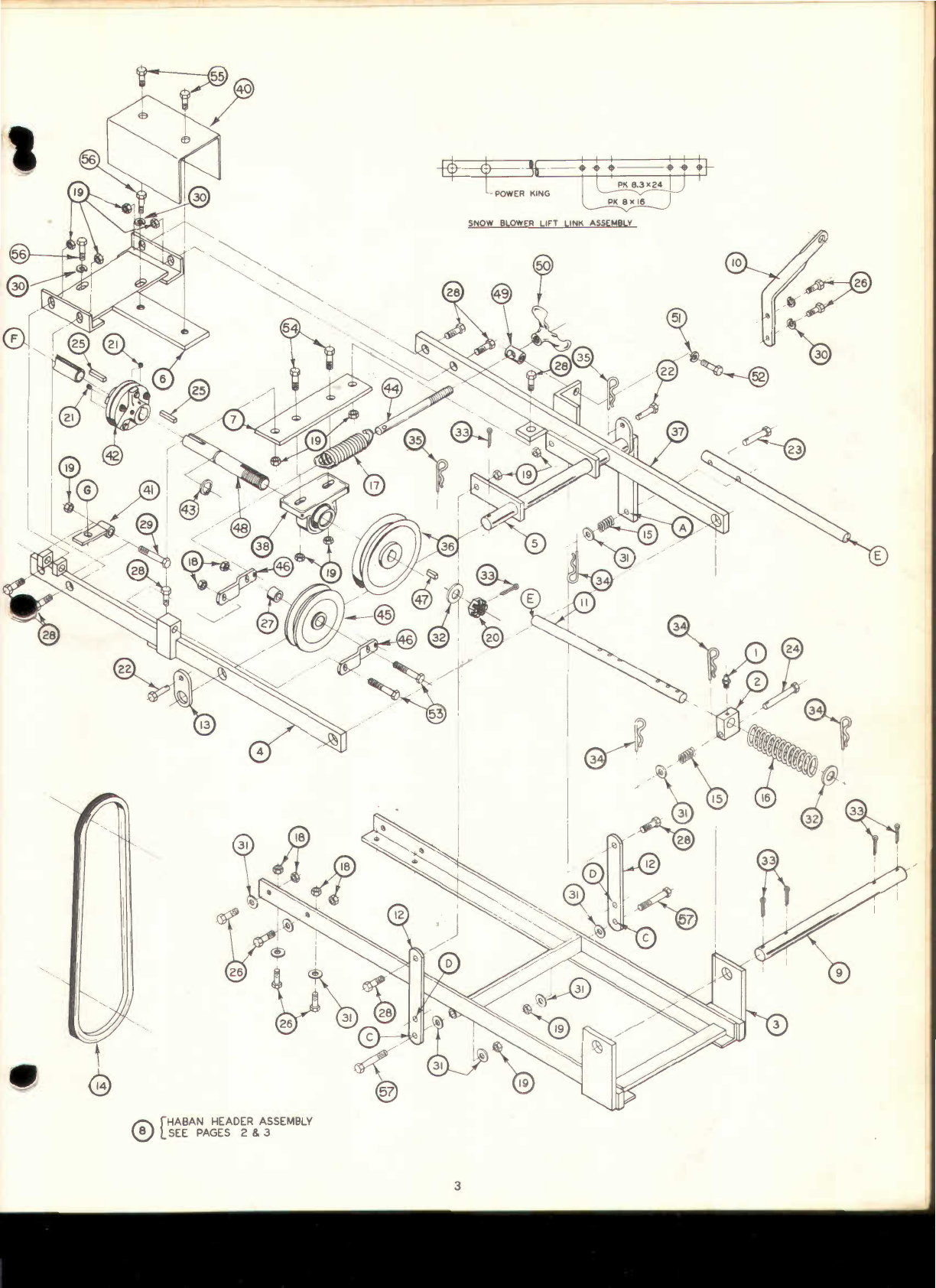
Assemble LIFT LINK (Item 11) as
shown
on page 3. It is very
important
that
the
KEYS (Item 34),
the
LIFT LINK BRACKET,
(Item 2),
the
SPRING (Item 16) and
the
WASHER (Item 32) be
in
the relative positions
shown
. This
arrangement
allows
the
HEADER
to
trip
up
when
a solid
object
is
struck and
therefore,
avoids
damage
to
the
HEADER, HITCH, and LIFT. The
length
of
the
LINK
is adjusted
for
the
various model
tractors
by placing
the
KEYS
and PINS in
the
appropriate locations. See
Diagram
on page 3.
Attach
the
LIFT LINK
to
lift
arm
on
Lift
Weldment
(Item 5) using
BOLT 7/
16"
x
2"
LONG BLANK (Item 23), SPRING (Item 15),
WASHER, 7/
16"
SAE FLAT (Item 31) and
KEY
#9
LARGE QUICK
CHANGE (Item 34).
Attach
the
CHUTE CRANK BRACKET (Item 1
0)
to
the
right
hand side
of
the
tractor
flywheel
housing.
Two
holes are provided
there
for
this
purpose. Use SCREW, 3/
8"
-24NF x 7/
8"
LONG
HHC (Item 26) and WASHER, 3/
8"
REGULAR LOCK (Item 30).
Place DISCHARGE CHUTE (Item 143) and DEFLECTOR
AS-
SEMBLY (Item 33)
through
the
DEFLECTOR DRIVE CABLE LOOP
(Item
120
and over
the
discharge stack on
the
HEADER.
Tighten
the
four BOLTS (Item
176)
at
the
DISCHARGE CHUTE base. These
BOLTS should
fit
under
the
ring on
the
HEADER
discharge
stack
to prevent
the
DISCHARGE CHUTE
from
coming
off
during
opera-
tion, yet
allow
it
to
rotate freely. Place both
interlocking
loops
of
the CABLE over
the
stud on
the
DISCHARGE CHUTE and
retain
with
WASHER, (Item 1
06)
and BOLT, 1I
4"
-20NC x 1/
2"
LONG
HEX
MACH
(Item
175)
.
The
Snow
Blower
is
now
fully
assembled and ready
for
mount-
ing,
final
adjustments
and operation.
MOUNTING
Mount
Snow
Blower
as
follows
:
Be sure
tractor
is on a level surface, is
not
running
and is
in
neutral. Place HEADER and HITCH ASSEMBLY
in
front
of
tractor
with
LIFT LINK extending
forward
toward
the
rear. Roll
the
tractor
forward
until HITCH PIVOT ROD is
just
slightly
ahead
of
tractor
rear
hitch
blocks. Leave
tractor
in
neutral
and
lift
rear of HITCH
and roll
tractor
forward
until
PIVOT ROD is in slot
in
rear
hitch
block. Tractor is
most
easily moved by
turning
tire,
either
front
or rear. Raise LIFT WELDMENT
until
bar
is
in
slot
of
tractor
front
hitch
block. Rotate HITCH LATCH
into
pos1t1on
and
retain
with
BOLT 3/
8"
x
2"
LONG BLANK (Item 22) and
KEY
, #11 ,
SMALL
QUICK CHANGE (Item 35).
Attach
rear end of LIFT LINK
to
tractor
lift
arm
using BOLT
7/
16"
x
3"
LONG BLANK (Item 24), SPRING (Item 15), WASHER
(Item 31) and
KEY
(Item 34). LIFT LINK should have already been
assembled
to
proper
length
referencing
the
diagram
on page 3.
Disconnect
the
Electromagnetic Clutch
wires
and
retaining
chain. Place BELT (Item 14) over clutch and
into
front
groove.
Reconnect
chain
and
wires.
It is desireable
to
wrap
the
wires
once
around
the
chain
when
reconnecting
to
avoid its rubbing on
the
engine screen and BELT
during
operation
.
Run BELT
down
around DRIVE SHAFT SHEAVE and around
IDLER SHEAVE.
Adjust
BELT
tension
by
turning
WING NUT so
that
about
1"
of
thread
shows
on BELT TENSIONING ROD. The
BELT
will
stretch
after
operation
begins
and
will
have
to
be re-
adjusted. Stop
engine
before making any adjustments.
Hook end of CRANK ROD (Item
135)
through
the
EYEBOLT
(Item 107) of chute
turning
assembly.
Slide
other
CRANK
ROD
(Item 107)
through
CHUTE CRANK (Item 10) and
into
the
end of
the
other
CRANK ROD.
ADJUSTMENTS
Adjust
SKID SHOES (Item 1
03)
to
the
desired
height
by block-
ing up
the
HEADER, loosening
the
BOLT (Item
131)
and NUT (Item
183), adjusting
Shoe
height, and
retightening
BOLT and NUT.
Adjust
both SHOES
to
the
same level.
If
operation
is
to
take place
on a gravel or stone
driveway
, etc
.,
it is recommended
that
the
SHOES
be
as
low
as possible. Both
the
SCRAPER BLADE (Item
101) and
the
SKID SHOES are subject
to
wear
and are designed
for easy replacement. Replace before
wear
is excessive
to
pre-
vent damage
to
the
auger housing.
A correctly adjusted AUGER CHAIN (Item
121)
will
have a
slight
amount
of
slack.
Adjust
this
CHAIN by loosening NUTS
(Item 161) at
the
HEADER end of
the
universal shaft, loosen
the
JAM
NUT (Item
168)
and
turn
BOLT (Item
150)
to
adjust CHAIN
tension. Clockwise
to
increase
tension,
counter-clockwise
to
decrease tension.
Re-tighten
JAM
NUT and NUTS (Item 161 ).
Check CHAIN periodically
to
maintain
proper
adjustment
. Do
not
run CHAIN
either
too
tight
or
too loose.
The DISCHARGE CHUTE CRANK is located on
the
right
hand
side of
the
tractor
. Turn CRANK to
control
the
direction
of
the
snow
discharge. The CHUTE rotates
thru
a
total
of
about
270°
and
should turn equally
far
in
either
direction
. Overtravel is
prohibited
by a chute stop bolt.
If
the
CHUTE travel is
not
the
same
in
both
directions, check
the
wrap
of
the
CABLE (Item
120)
and
the
TUBE
(Item 118). It should be
wrapped
2-1 / 2
times
around
the
TUBE
in
each direction.
If
the
DISCHARGE CHUTE
will
not
hold
in
a set
position,
tighten
the
NUT (Item 184)
until
the
CHUTE does
hold
its
position. Do
not
overtighten
.
The DEFLECTOR (Item 133) mounted on top
of
the
DISCHARGE
CHUTE
determines
the
distance
snow
is
thrown
.
Moving
the
top
of
the
DEFLECTOR
down
decreases
the
distance
while
raising
the
DEFLECTOR increases it.
/'),.SHUT
OFF
ENGINE
WHENEVER
ANY
ADJUSTMENTS/'),.
·
..
TO
THE
SNOW
BLOWER
ARE
MADE!
..

OPERATION
Before
the
first
snowfall,
the
area in
which
snow
removal is
to take place should be cleared
of
all stones, sticks and
the
like
which
might
be
picked up by
the
auger.
All
obstacles should be
marked to protect
the
tractor
and auger
from
possible collision.
Check
the
tractor
and
Snow
Blower
to
be sure
that
both are
in
good operating condition.
A
light
coat of
wax
or
a coat
of
a silicone spray
lubncant
applied
to
the
inside surfaces
of
the
auger housing
will
prevent
snow
and ice
from
sticking to it. The
wax
or spray should be
applied several
times
during
the
snow
removal season.
Fill gas
tank
out of doors and avoid
spilling
gasoline
over
the
engine. Do
not
fill
tank
while
smoking or
while
engine
is
running
.
Allow
ample engine
warm
up
time
before
starting
snow
re-
moval.
To become
familiar
with
the
controls, operate
the
tractor
and
Snow
Blower
in a clear area before
attempting
to
remove
snow
.
The more
familiar
you become
with
the
Snow
Blower
and its oper-
ation,
the
better
results you
will
have.
For best results,
snow
should be removed as soon as possible
after it falls.
Do
not
remove
any
guards
or
covers
while
operating
the
tractor and
Snow
Blower
.
Also
do
not
operate
with
any
guards
removed.
The auger speed is
directly
related to
engine
speed. For
maxi-
mum
snow
removal and discharge,
maintain
high
engine
RPM (full
throttle). It is advisable
to
operate
the
tractor
at
a very
slow
ground speed
for
safe and
efficient
snow
removal. A
tandem
trans-
mission is
highly
recommended.
If
the
snow
cover is
extremely
deep, raise
the
Header
to
its
highest position and
drive
forward
until
the
tractor
tires
reach
the
unblown
snow
. Do
not
drive
onto
this
snow.
Back up,
lower
header, and drive
forward
again. In
this
manner
the
deepest
snow
can
be
removed.
The use
of
tire
chains
and
wheel
weights
is
recommended
for
extra
traction
especially
when
heavy
snows
or
icy
conditions
occur.
Whenever
possible discharge
snow
downwind
.
Do
not
attempt
to
remove ice or hard packed frozen
snow.
Always
overlap each pass
slightly
to assure complete
snow
removal.
A frozen or stuck auger
or
elbow
must be broken loose or
thawed
with
care.
When
attempting
to loosen a
jammed
auger,
shut
off
tractor
engine and remove spark plug
wire.
Never
attempt
to clear
Snow
Blower
at any
time
with
tractor
engine
running.
If
the auger suddenly comes unstuck, you
will
loose your fingers!
A
definite
pattern is required
for
thorough
and
efficient
snow
removal. If
snow
can
be
blown
to
either
side,
start
the
first
pass
in
the
center
of
the
area.
With
each additional pass
alternate
sides
of
the
cleared area and
blow
the
snow
over
the
uncleared area.
If
snow
can be
blown
only
to
one side,
start
at
the
other
side
of
the
area and
blow
the
snow
in
one
direction
only
.
Alternate
the
angle of
the
discharge chute
with
each pass.
Be extremely careful as
the
Snow
Blower
will
throw
objects
other
than
snow. Keep children, adults and
animals away
to avoid
any danger
to
them
both
from
thrown
objects and
from
contact
with
the
rotating auger.
After
the
area has been cleared and
the
Snow
Blower
is
to
be
put away, be sure
that
the
auger housing and discharge chute
are clear of all
snow
and slush, especially slush.
If
the
tempera-
ture drops and
the
slush
or
snow
freezes in
the
header, it
may
become
virtually
impossible
to
clear
it
without
applying heat.
At
the end
of
the
season
the
following
steps are recommended:
Wash
off
any
salt deposit
which
may
have
dried
on
the
Snow
Blower
and housing. Paint or cover exposed metal
with
a
light
coat
of
oil.
Lubricate
the
Snow
Blower
following
the
lubrication
instruc-
tions. The
Snow
Blower
chain
must
be oiled
thoroughly
to
prevent
rust from forming.
Store
Snow
Blower
in a
dry
place.
2
LUBRICATION
Auger Chain:
Lubricate
chain
with
30
weight
oil
every
20
operating hours. Be sure oil reaches inside each
roller
.
Wipe
off
excess oil.
Pivot and Friction Points: To
maintain
smooth and free opera-
tion apply a
few
drops
of
30
weight
oil as required
to
all
friction
and pivot points.
Deflector: Lubricate defector
with
a
water
repellent
grease
as needed.
Bearings: Lubricate Header
Bearings
and
pillow
block bearing
after every
50
hours of operation
with
a good
wheel
bearing grease.
The header grease
fittings
are located on
the
right
side
when
facing
the
front
of
the
header. The
Pillow
Block grease
fitting
is
located on
the
Pillow
Block housing. Be .careful
not
to
overfill
the
bearings.
Also
be sure
to
wipe
the
fittings
clean before greasing
to prevent
dirt
from
being forced
in
the
bearings and
after
they
have been lubricated.
ITEM
1
2
3
4
5
6
7
8
9
10
11
12
13
14
15
16
17
18
19
20
21
22
23
24
25
26
27
28
29
30
31
32
33
34
35
36
37
38
40
41
42
43
44
45
46
47
48
49
50
51
52
53
54
55
56
57
P/N
03
·
2102
15·0505
50·0104
50
·
0115
50·0130
50·2502
50·2505
50
·
0110
50
·
0111
50
·
0505
50-4701
50
·
4704
51
-
4705
81
·
0048
83
·
0024
83
·
0124
83
·
0005
84·0110
84
·
0120
84
-
0073
84
·22
60
84
-
1101
84·1111
84·1121
84
·
4012
84
·2
110
83
·
0127
84·2171
84
·2
210
84
·
3020
84
·3
060
84
·
3070
84-4020
84-4031
84-4032
6346
50·0114
80·0505
50
-2
515
50-4708
50·0525
99·0011
09
·
0053
86
·0
061
60
·
0509
84-4011
50·5050
99
·
0252
84
·
0051
84
-3
010
84
·2
030
84
·
2151
84
·2
170
84
·2
010
84
·2
111
84·2220
Read all
safety
rules
on
page
6
before
attempting
to
operate
Snow
Blower.
48"
SNOW
BLOWER PARTS LIST
DESCRIPTION
FiniNG
...
Grease
114"
-
28
short
BRACKET
.. ..... .
Lift
Link
WELDMENT
............
..
.........
.48"
Snow
Blower
Hitch
WELDMENT
........................
Left
Hanger
WELDMENT
.....
..
.....
..
..
.
..
.
..
.48
"
Snow
Blower
Lift
WELDMENT
.............
..
..
......
Gear
Box
Mounting
BRACKET
......................
Bearing
Support
ASSEMBLY
... ..........
..
.48
"
Snow
Blower
Header
ROD
.................
....
.........
..
Hitch
Pivot
Mounting
BRACKET
...... .....
..
......
Chute Crank
LINK
...................
.46"
Universal
Lift
LINK
.........
....
.......
..
.
LiftArm
LATCH
.. ..............
Hitch
BELT
.....
..
....
..
.
.For
Model1978
48
"
Snow
Blower
SPRING
.......
..
.....•............
Compression
1"
Long
SPRING
. ............... .......
Compression
6"
Long
SPRING
..........
Extension
5-3
/
8"
Long
NUT
.. ...........
.3
/8" -
24NF
Hex
Lock
NUT
......•..........•.......
.7
I
16
" -
20NF
Hex
Lock
NUT
............3/ 4" -
16NF
Hex
Slotted
SCREW
.....
..
......
....
.5/
16"-
18NC
x3/8"
Long
SOC
HSS
BOLT
.....................
.3
/8" x2"
Long
Blank
BOLT
............ .... ........
.7
/
16
" x2"
Long
Blank
BOLT
...............................
.7
/
16
" x3"
Long
Blank
KEY
.................................3/
16
"
Square
x 1·7/
16
"
Long
SCREW
............................
.3
/8" -
24NF
x7/8"
Long
HHC
SPACER
............................
Idler
Assembly
SCREW
............................
.7
/
16
" -
20NF
x 1·1/4"
Long
HHC
SCREW
.........•
..
.........
.. ..
.
..
.7
/
16
" -
20NF
x2
·112''
Long
HHC
WASHER
.................
.3
/
8"
Regular
Lock
WASHER
.................
.7
/
16
"
SAE
Flat
WASHER
......3/4"
SAE
Flat
KEY
.... ............5/
32"
x1·1/2"
Long
Cotter
KEY
......
#9
Large
Quick
Change
KEY
.....
..
................
..
.
..
.
..
#11
Small
Quick
Change
ASSEMBLY
...•...
..
......
Pulley
and
Hub
WELDMENT
........................
Right
Hanger
BEARING
...........................3/ 4"
Pillow
Block
GUARD
..............
..
.............
Drive
Shaft
BRACKET
...........................
Header
Drive
Guard
COUPLING
.....................
Drive
Shaft
to
Gear
Box
-
Flexible
SNAP
RING
...... .........
Drive
Shaft
ROD
.................................
Belt
Tightener
SHEAVE
...................•........5" 0.D.
Flat
BRACKET
...........................
Idler
KEY
..
..
..
. .
..
3/
16
"
Square
x7/8"
SHAFT
... ....................
Drive
GUIDE
..............................
Belt
Tightener
Rod
WING
NUT
...........
..
..........
..
Belt
Adjustment
WASHER
.....................
..
...5/
16"
Regular
Lock
SCREW
...........................
5/
16"-
24NF
x7/8"
Long
HHC
SCREW
.........
..
..
........
.3
/8" -
24NF
x2·1/2"
Long
HHC
SCREW
.
.7
/
16
" -
20NF
x1·
112
"
Long
HHC
SCREW
...5/
16
"-
24NF
x 1/2"
Long
HHC
SCREW
.................
.3
/
8"-
16NC
x7/8"
Long
HHC
SCREW
........7/
16
" -
20NF
x
3·1
/ 4"
Long
HHC
SPECIAL
INSTRUCTIONS
FOR
MOUNTING
ON
1980
MODEL
TRACTORS
(after
serial
#
52589)
This
48
11
Snowblower
incorporates
parts
and
features
that
allows
it
to
be
mounted
on
1973
through
1979
model
Power
King
tractors
(except
Jim
Dandy
and
1612
models),
and
on
1980
models
with
a
revised
hydraulic
lift
system
(after
serial
number
52589).
For
tractors
with
serial
numbers
prior
to
this,
the
assembly
instructions
and
parts
illustrations
as
shown
on
pages
1
through
6
of
the
Operators
Manual
are
correct.
If
this
Snowblower
is
to
be
used
on
a
1980
model,
substitute
the
following
procedure
for
assembling
the
lift
link
(paragraph
6,
page
1)
and
refer
to
the
illustration
on
the
opposite
side
of
this
sheet
in
place
of
page
3.
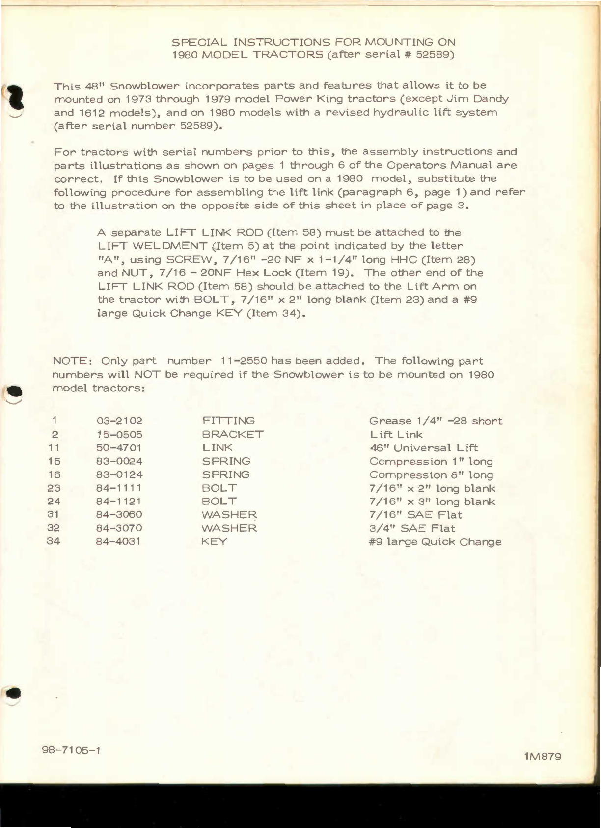
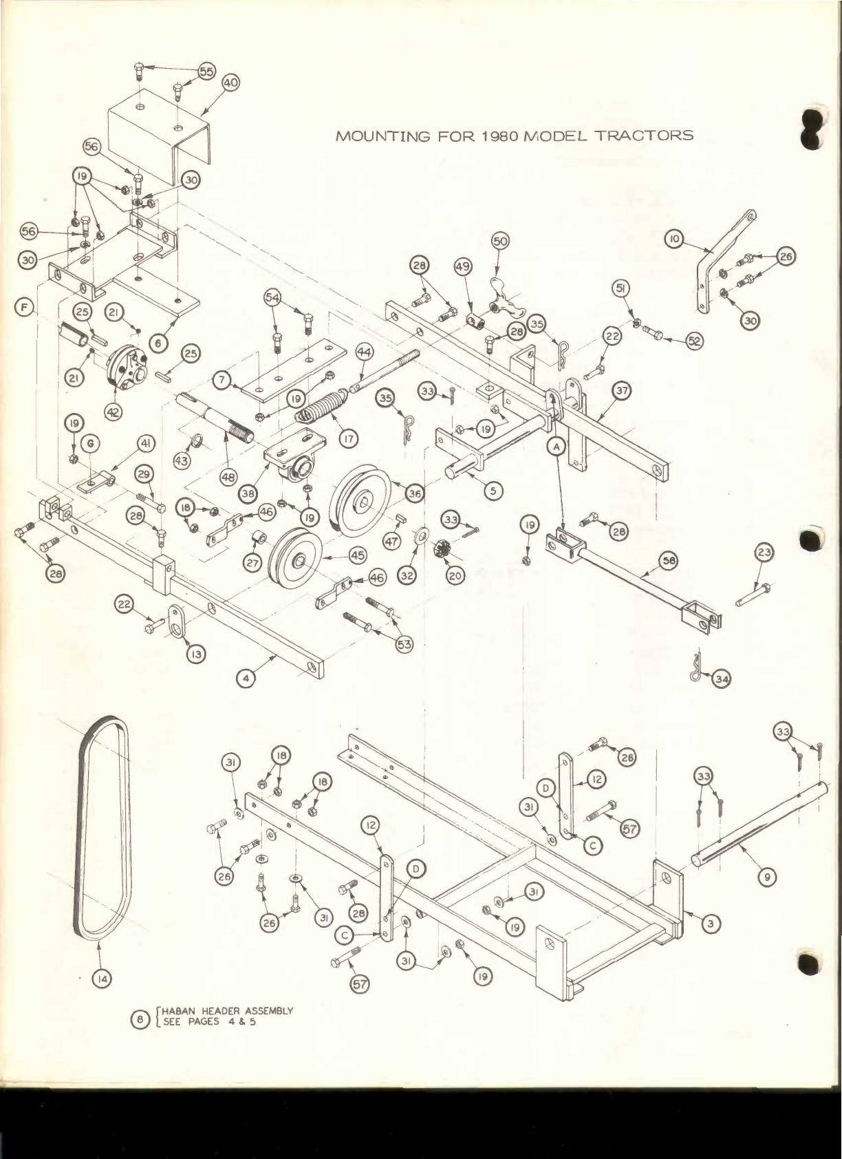
A
separate
LIFT
LINK
ROD
(Item
58)
must
be
attached
to
the
LIFT
WELDMENT
(Item
5)
at
the
point
indicated
by
the
letter
"A",
using
SCREW,
7/16"
-20
NF
x
1-1/4"
long
HHC
(Item
28)
and
NUT,
7/16
-
20NF
Hex
Lock
(Item
19).
The
other
end
of
the
LIFT
LINK
ROD
(Item
58)
should
be
attached
to
the
Lift
Arm
on
the
tractor
with
BOLT,
7
/16"
x
2"
long
blank
(Item
23)
and
a
#9
large
Quick
Change
KEY
(Item
34).
NOTE:
Only
part
number
11-2550
has
been
added.
The
following
part
numbers
will
NOT
be
required
if
the
Snowblower
is
to
be
mounted
on
1980
model
tractors:
03-2102
FITTING
Grease
1I
4"
-28
short
2
15-0505
BRACKET
Lift
Link
11
50-4701
LINK
46"
Universal
Lift
15
83-0024
SPRING
Compression
1"
long
16
83-0124
SPRING
Compression
6"
long
23
84-1111
BOLT
7
/16"
x
2"
long
blank
24
84-1121
BOLT
7
/16"
x
3"
long
blank
31
84-3060
WASHER
7
/16"
SAE
Flat
32
84-3070
WASHER
3/4"
SAE
Flat
34
84-4031
KEY
#9
large
Quick
Change
98-7105-1
1M879
DER
ASSEMBLY
fa\
[HABA~A~g
4 & 5
V::../
SEE
D
EL
T
1980
MO
MOUNTING
FOR
RA
CTORS
37
J
DER
ASSEMBLY
17:\
[HABANPA~ft
2 & 3
\:::.I
SEE

HABAN
48
, HEADER ASSEMBLy

ITEM
P/N
101
3013A
102
3036
103
3045
104
3076
105
3259
106
3903
107
3955
108
4119
109
4143
110
4506
111
4606
112
4607
113
4608
114
4609
115
4610
116
4611
117
4123
118
4742
119
4772
120
5098
121
5101
122
5429
123
5473
124
5474
125
6023
126
6024
121
6340
128
6558
129
7090
130
7091
131
7953
132
3396
133
8197
134
8198
135
8206
136
8236
137•
8287
138
8299
139
11356
140
8362
141
8363
142
8456
143
8585
144
8725
145
9030
146
9032
147
9125
148
9127
149
9129
150
9132
151
9175
152
9177
153
9345
GEARCASE
IS
SHOWN
IN
ITS
MOUNTED ORIENTATION. SEE
AS-
SEMBLY INSTRUCTIONS
FOR
PROPER
INSTALLATION,
HABAN
48"
SNOW
BLOWER
HEADER
PARTS LIST
DESCRIPTION
BLADE
............... .....
Scraper
GUARD
............
..
Chain
SHOE
. .......................
Skid
HOOK
. .......................
Lift
SP,ring
KEY
. ..
..
...................3/16'
Square
x I"
Long
WASHER
..
.....................
Concave
Tooth
EYE
BOLT
.......
.
................
Drive
Tube
NUT
...
..
. .
..
..
.
..
..
...... .....
.1
/
4"-
20NC
HEX
Lock
(84-0010)
WASHER
.............
..
....
..
..
..
.
Auger
WASHER
.........................
.1
-1/2" O.D. x
13
/
32"
I.D.
x .
0511
.
080
BUSHING
.. .........
Gear
Box
GEAR
BOX
.. .......................
Right
Angle
GASKET
..
.....
.
....
...............
Gear
Box
SNAP
RING
..
............
Gear
Box
SNAP
RING
...........
Gear
Box
BEARING
. ............
Gear
Box
FiniNG
.....................
Grease
TUBE
...... ......
....
.
..
.
....
...
Deflector
Drive
WASHER
......
.................
.
13
/
16"
O.D
. x 13/32"
I.D.
x 5/
64"
Thick
CABLE
.........
..
...................
Deflector
Drive
CHAIN
.........
..
...................
Auger
Drive
WASHER
..........................
.1
-11
16"
O.D. x
49
/
64"
I.D.
x0.
0598"
Thick
FLANGE
.. ......
.. .. ..
.....
Bearing
BEARING
...................
Auger
ASSEMBLY
..
.......
..
......
Shaft
and
Gear
ASSEMBLY
..........
....
....
Gear
Box
SLEEVE
..
...........................
Oval
MOLDING
......
..
..................
Deflector
BOLT
........
......................
.1
/
4"-
20NC
x 5/ 8"
Long
Carriage
PLUG
..... .....................
Pipe
BOLT
.....................5/
16"-
18NC
x3/
4"
Long
Carriage
WASHER
.......
..
...
.1-112"
O.
D.
x49/64"
I.D
. x 0.
0598"
Flat
DEFLECTOR
.... ................
Elbow
STRAP
...............
.Locking
ASSEMBLY
. ................
Crank
Rod
U-BOLT
.. ..............
..
Deflector
Drive
SPROCKET
.......................
..
35
Tooth
Auger
STRAP
...
..
......... ...........
....
.Friction
ASSEMBLY
.........
..
....
..
........
Sprocket
and
Bearing
SHAFT
.....
Auger
ASSEMBLY
.
..
.................
Auger
48"
KIT
...
..
................
Chain
Repair
ASSEMBLY
....................
..
...
Elbow
and
Pivot
ASSEMBLY
.........................
Cable
,
Tube
and
Sleeves
SHROUD
...........................
Stack
Drive
ASSEMBLY
.........................
Bracket
and
Tube
ASSEMBLY
.. .. ..
..................
.Jackshaft
Housing
ASSEMBLY
.........................
Jackshaft
Housing
ASSEMBLY
.........................
Jackshaft
and
Sprocket
13
Tooth
BOLT
................................
5/16"-
18NC
x
1-3
/
4"
Long
Sei!Tapping
SPACER
...........................
.Jackshaft
SLIP
ASSEMBLY
...................
Male
End
ASSEMBLY
. ................
Crank
Rod
5
ITEM
P/N
154
9663
155
10440
156
10441
157
10442
158
10444
159
GM-102594
160
GM
-
120214
161
GM-120378
162
GM-120380
163
GM-120384
164
9737
165
GM-120388
166
GM
-
120389
167
GM
-
120915
168
GM
-
124824
169
GM-124829
170
GM-126227
171
GM-126358
172
GM
-
126803
173
GM
-
180024
174
GM
-
178566
175
GM
-
180016
176
GM-180018
177
GM
-
9411507
178
GM-180044
179
GM-180077
180
GM-9428225
181
GM
-
180175
182
GM-271178
183
GM-271184
184
GM-271190
185
GM-9413534
186
GM-9414012
187
10509
188
10395
189
5681
190
10397
191
GM
-
180126
192
GM-180137
193
4409
194
GM-180075
195
GM-180116
196
GM-120382
197
GM-9413447
198
11354
199
11353
DESCRIPTION
DECAL
.............................
Chute
Warning
ASSEMBLY
........................
Header
Housing
48"
ASSEMBLY
.............
..
... .. .
.48"
Auger
Complete
ASSEMBLY
................ .
Stack
Dnve
Complete
SLIP
ASSEMBLY
..........
..
......
.Female
End
SCREW
............................
.3
1
8"
..
-
16NC
x 5/ 8"
Long
AI
Hd
Cp
Pt
Set
WASHER
..................
..
.
..
....5/
16
Med1um
Lock
(84-3010)
NUT
....... .................1/2" -
13NC
Lt
Hex
WASHER
..........................
.1
/4:
Medium
Lock
(84
-
3040)
WASHER
...........................1/2
Med1um
Lock
(84-3110)
ASSEMBLY
.........................
Deflector
and
Decal
WASHER
...........................3/8"
Flat
WASHER
..........................
.7
/
16"
Flat
(84-3060)
BOLT
.... ..... .......
..
......
.3
/
8"-
16NC
x
I"
Long
Carriage
NUT
. .
..
........
..
........
5/16"-
18NC
x
Half
Hex
NUT
.3/8"-
16NC
Lt
Hex
BOLT
........
.3
/
8"-
16NC
x3/
4"
Long
Carriage
BOLT
. .
..
......5/
16"-
18NC
x 1"
Long
Carriage
BOLT
............. .
..
.1/2"-
13NC
x3-1/2"
Long
Carnage
BOLT
..
.....................
.1
/
4"-
20NC
x 1-1/4"
Long
WASHER
......................
.3
/ 8"
Internal
BOLT
............
114"-
20NC
x 1/2"
Long
Hex
Mach
(84-1012)
BOLT
................................1/4" -
20NC
x5/
8"
Long
Hex
Mach
NUT
................................
.3
/
8"
-
16NC
Serrated
Flange
Hex
Lock
BOLT
...............................
.1
/4" -
20NC
x2"
Long
Hex
Mach
BOLT
................................5/
16"-
18NC
x3/ 4"
Long
Hex
BOLT
...............................
.3
/
8"-
16NC
x
I"
Flanged
Hex
Hd
BOLT
...............................
.1/2"-
13NC
x 1-1/
4"
Long
Hex
Mac
NUT
............
.1
/
4"
-
20NC
Hex
with
Lock
Washer
NUT
... .
......................
.5/
16"-
18NC
Hex
with
Lock
Washer
NUT
................................
.3
/
8"-
16NC
Hex
with
Lock
Washer
NUT
...
..
..... ..........
.3
/
8"-
16NC
Hex
Lock
(84-0040)
SCREW
..................
....
.
..
.
..
.1
/
4"-
14
x 1/2"
Long
Self
Tapp1ng
GUARD
.......
..
....
..
..............
PTO
Bottom
GUARD
........................
PTO
Top
SPRING
...........
WASHER
..................
..
.......
Special
Wing
BOLT
...................
..
........
..
.3
/
8"-
16NC
x 1-1/2"
Long
Hex
Mach
BOLT
3/ 8" -
16NC
x
2-3
/
4"
Long
Hex
Mach
SPACER
............................
BOLT
................ .
..
5/
16"-
16NC
x 1/ 2"
Long
Hex
Mach
BOLT
..
..
....
..
..
..
..
.
..
. 3/
8"-
16NC
x 1/2"
Long
Hex
Mach
WASHER
.................
..
.....
..
.3
/
8"
Medium
Lock
Nut
NUT
..... .
..
.............
Deflector
ASSEMBLY
.........................
Idler
Bracket
ASSEMBLY
......... ................
Idler
Bracket
Complete
The
above
parts
and
their
part
numbers
refer
to
parts
which
are
serviced
by
Haban
Manu
-
facturing
Company,
2100
Northwestern
Avenue
,
Racine
,
Wisconsin
53404
. If
replacement
parts
are
needed
please
order
them
directly
from
Haban
.
Parts
which
are
common
to
the
Engineering
Products
Company
system
also
have
their
Engineering
Products
part
number
given
in
parentheses
following
the
part
description
(84-0010)
.
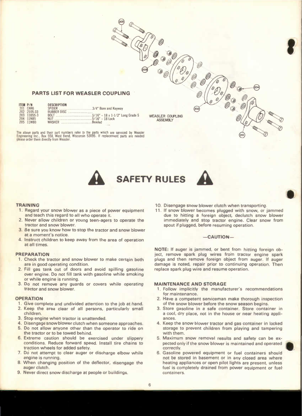
PARTS LIST FOR WEASLER
COUPLING
ITEM
P/N
201
C4R6
202
2105-33
203
11B55
-3
204
11N85
205
11W80
DESCRIPTION
SPIDER
..
..
RUBBER
DISC
BOLT.
NUT.
WASHER
..
.3
/
4"
Bore
and
Keyway
.5/
16"-
18
x
1-112
"
Long
Grade
5
....................5/
16"-
18
Lock
........
.Beaded
The
above
parts
and
their
part
numbers
reler
to
the
parts
which
are
serviced
by
Weasler
Engineering
Inc
.,
Box
558
,
West
Bend,
Wisconsin
53095
.
II
replacement
parts
are
needed
plea
se
order
them
directly
lrom
Weasler
.
WEASLER
COUPLING
ASSEMBLY
202
A SAFETY RULES A
TRAINING
1. Regard your
snow
blower
as a piece
of
power
equipment
and teach
this
regard to all
who
operate
it
2.
Never
allow
children
or
young
teen-agers
to
operate
the
tractor
and
snow
blower.
3.
Be sure you
know
how
to stop
the
tractor
and
snow
blower
at a
moment's
notice.
4.
Instruct
children
to keep
away
from
the
area
of
operation
at all times.
PREPARATION
1.
Check
the
tractor
and
snow
blower
to make certC!in both
are in good operating condition.
2.
Fill gas
tank
out
of
doors and avoid
spilling
gasoline
over engine. Do
not
fill
tank
with
gasoline
while
smoking
or
while
engine
is
running.
3. Do
not
remove
any
guards
or
covers
while
operating
tractor
and
snow
blower.
OPERATION
1. Give complete and undivided
attention
to
the
job
at hand.
2. Keep
the
area clear
of
all persons,
particularly
small
children.
3.
Stop
engine
when
tractor
is unattended.
4. Disengage
snow
blower
clutch
when
someone
approaches.
5.
Do
not
allow
anyone
other
than
the
operator
to ride on
the
tractor
or
to be
towed
behind
.
6. Extreme caution should be exercised
under
slippery
conditions
. Reduce
forward
speed.
Install
tire
chains
to
traction
wheels
for
added safety.
7.
Do
not
attempt
to clear auger
or
discharge
elbow
while
engine
is running.
8.
When
changing position
of
the
deflector, disengage
the
auger clutch.
9.
Never
direct
snow
discharge
at people
or
buildings
.
6
10
. Disengage
snow
blower
clutch
when
transporting
.
11
.
If
snow
blower
becomes plugged
with
snow,
or
jammed
due
to
hitting
a foreign object, declutch
snow
blower
immediately
and stop
tractor
engine. Clear
snow
from
spout
if
plugged, before
resuming
operation.
-CAUTION-
NOTE: If auger is
jammed,
or
bent
from
hitting
foreign
ob-
ject, remove spark plug
wires
from
tractor
engine
spark
plugs and
then
remove foreign object
from
auger.
If
auger
damage is noted, repair
prior
to
continuing
operation
.
Then
replace spark plug
wire
and resume operation.
MAINTENANCE
AND
STORAGE
1.
Follow
implicitly
the
manufacturer's
recommendations
for
maintenance
.
2. Have a
competent
serviceman make
thorough
inspection
of
the
snow
blower
before
the
snow
season begins.
3. Store gasoline in a safe
container.
Store
container
in
a cool,
dry
place,
not
in
the
house
or
near
heating
appli-
ances.
4. Keep
the
snow
blower
tractor
and gas
container
in
locked
storage to
prevent
children
from
playing
and
tampering
with
them
.
5.
Maximum
snow
removal results and safety can be ex-
pected
only
if
the
snow
blower
is
maintained
and
operated
correctly.
6.
Gasoline
powered
equipment
or
fuel
containers
should
not
be
stored in
basement
or
in
any
closed area
where
heating appliances
or
open
pilot
lights
are present, unless
fuel is
completely
drained
from
power
equipment
or
fuel·
containers.
This manual suits for next models
3
Table of contents


