EPHESUS Stadium User manual

INS #
Brand Logo
reversed out of
black
INS #
IB528002EN
Installation Instructions - Stadium Series
SAFETY INSTRUCTIONS
Read and understand this entire manual before attempting to assemble, operate, or install the LED Luminaire. If you
have any questions regarding the product, please call Ephesus Customer Service at (315) 579-2873.
1. All electrical work must conform to the National Electric Code (NEC) and all applicable local codes and ordinances.
2. Only qualified personnel shall install and maintain the luminaires. Ephesus recommends that a licensed electrician
install and maintain the luminaire. Verify the safety of existing power distribution system before beginning
installation. FAILURE TO FOLLOW OPERATING INSTRUCTIONS MAY LEAD TO DEATH, SEVERE INJURY, OR
PROPERTY DAMAGE.
WARNING
Turn off power before performing any electrical or control work. FAILURE TO FOLLOW THIS WARNING MAY LEAD
TO DEATH, SEVERE INJURY, OR PROPERTY DAMAGE.
DO NOT make or alter any open holes in the luminaire. Do not modify the luminaire.
WARNING
Follow all applicable safety procedures and use Personal Protective Equipment such as hardhats, safety glasses,
reflective vests, electrical safety gloves, fall protection equipment and safety toe boots during the installation,
operation, and maintenance of the luminaire. FAILURE TO FOLLOW THIS WARNING MAY LEAD TO DEATH,
SEVERE INJURY, OR PROPERTY DAMAGE.
WARNING
Risk of eye injury! Eye protection is required at all times during the installation, operation, and maintenance of
the luminaire. The high intensity light produced by the luminaire can cause severe damage to the eye if viewed
directly at close range. Avoid being in front of a luminaire that is on or wear suitable light blocking protective
eyewear such as welding goggles.
This manual applies to the following models of luminaires:
1. Stadium Pro
2. Stadium

2EATON IB528002EN Installation instructions rev 20171011
Installation Instructions - Stadium Series
ote:N Charge the provided laser battery before installation begins.
Required Materials & Tools
TABLE OF CONTENTS
Safety Instructions .................................................................................................................................................................1
Required Materials & Tools ....................................................................................................................................................2
Supply Power Specifications..................................................................................................................................................2
Installation..............................................................................................................................................................................4
Step 1 – Mount the Luminaires .........................................................................................................................................4
Step 2 – Label the Luminaires (If Required).......................................................................................................................6
Step 3 – Make Electrical Connections ...............................................................................................................................7
Step 4 – Aim the Luminaires..............................................................................................................................................9
Step 5 – Finishing Touches ...............................................................................................................................................13
Care and Maintenance .........................................................................................................................................................14
Troubleshooting....................................................................................................................................................................14
Required Material: For more information refer to Section:
Mounting Hardware (3/4” mounting bolt, 2 matching
flat washers, 1 matching nut)
Step 1 - Mount the Luminaires
Electrical splicing connectors Step 3 – Make Electrical Connections
Cable ties or wire management Step 4 – Aim the Luminaires
Required Tools Installer shall provide For more information refer to Section:
Socket wrenches and/or crescent wrenches sized to
fit mounting hardware (3/4” for mounting)
Step 1 - Mount the Luminaires
DMX Tester/RDM Controller Step 3 – Electrical Connections
15/16” socket driver for hex bolt Step 4 – Aim the Luminaires
Torque wrench rated to a minimum of 35 ft-lbs Step 4 – Aim the Luminaires
Torque driver with 3/16” hex bit rated to a minimum
of 35 in-lbs
Step 4 – Aim the Luminaires
Calibrated light meter Step 4 – Aim the Luminaires
Tools Provided by Ephesus For more information refer to Section:
Aiming Laser Step 4 – Aim the Luminaires
Aiming Mount Step 4 – Aim the Luminaires
Storage Temperature Operating Temperature Humidity
-40°C to +75°C (-40°F to 167°F) -40°C to +55°C (-40°F to 131°F) 5% to 95% non-condensing
Store luminaires in a clean, dry place, protected from dirt, water, and sunlight. See Table 1 for required storage and operating
conditions:
Table 1. Storage and Operating Conditions
Supply Power Specifications
Ephesus LED light fixtures are not traditional incandescent lights, they are high-tech, new generation solid-state devices.
To protect your valuable investment, the electrical power shall be clean and have stable voltage and current and undistorted
waveforms.

3
EATON IB528002EN Installation instructions rev 20171011
Installation Instructions - Stadium Series
WARNING
Follow proper grounding methods: Electrical system must be grounded. If you are not sure if your power system is
grounded, DO NOT install the luminaire. Contact a licensed electrician for information on proper grounding methods
as required by the electrical code. FAILURE TO FOLLOW THIS WARNING MAY LEAD TO DEATH, SEVERE INJURY, OR
PROPERTY DAMAGE.
Circuit Voltage
Branch power circuits feeding Stadium fixtures shall be 240V, 277V, 347V, or 480V AC only.
WARNING
Do not attempt to connect Stadium fixtures to any circuits with nominal voltage below 240V or above 480VAC.
FAILURE TO FOLLOW THIS WARNING MAY LEAD TO LUMINAIRE INTERNAL DAMAGE AND FAILURE.
Fusing
If individual branch circuit protection is required, Table 2 shows the minimum fuse ratings for each individually circuited
luminaire.
Circuit Voltage
(VAC)
Minimum Fuse
Rating (amps)
240 8
277 7
347 5
480 4
Table 2. Minimum Fuse Ratings
Figure 1. Acceptable Power Configurations
Three Phase Four Wire Wye Single Phase
Phase A
Phase B
Neutral
277V
(or 347V)
277V
(or 347V)
277V
(or 347V)
480V*
240V
480V*
480V*
Phase C
Line 1
Neutral
Line 2
*Never connect fixtures to 600VAC
Power Configuration
The power transformer secondary feeding the electrical distribution system must be a three-phase, four-wire wye
configuration. A single phase configuration is acceptable in the case of 240V circuits. If any other transformer configuration is
present, notify Ephesus before proceeding with installation.

4EATON IB528002EN Installation instructions rev 20171011
Installation Instructions - Stadium Series
Power Quality
The voltage on the lighting circuits must stay within 3% of nominal at 60Hz. Voltage that is consistently too high or low shall
be corrected before LED luminaires are installed.
If you require assistance in checking your power system or designing or implementing solutions, contact Eaton’s Electrical
Engineering Services and Systems. Find more information at www.eaton.com.
Hardware Required Size Quantity per luminaire
Hex bolt 3/4” 1
Flat washers 3/4” ID 2
Hex Locknut 3/4” 1
Equipment Required:
Mounting Hardware
Socket wrenches and/or crescent wrenches sized to fit mounting hardware
Cable ties or wire management – For outdoor installations use UV rated.
Before installation, verify there are no obstructions in the designed luminaire locations and light paths. If beams,
rigging, or any other obstructions are present, shift the mounting location up to +/-2’ in either direction to install the
fixtures in the closest available location to provide a clear conical light path from the fixture to a 20’ diameter circle
around the aiming point that is completely free of obstructions.
All LED arrays in each fixture must have clear line of sight to aiming area. Do not install fixture partially obscured.
Step 1 – Mount The Luminaire
The first step is to attach the luminaire to the mounting structure. The mounting structure may be a light pole cross arm, an
indoor catwalk bracket, or other structural component that will hold the fixture in place. Refer to photometric drawings or
project Installation Drawings for luminaire installation locations and any additional mounting instructions.
WARNING
It is the responsibility of the installer to verify that all proposed mounting structures including poles, cross arms,
catwalk brackets, and other mounting structures are certified to support the weight of the luminaires, withstand
wind loads, and meet all other applicable codes and regulations. FAILURE TO FOLLOW THIS WARNING MAY LEAD TO
DEATH, SEVERE INJURY, OR PROPERTY DAMAGE.
WARNING
Do not suspend any luminaire by electrical or control wires, as these will not support the weight of the fixture,
resulting in the potential for the fixture to fall and cause damage or injury. FAILURE TO FOLLOW THIS WARNING MAY
LEAD TO DEATH, SEVERE INJURY, OR PROPERTY DAMAGE.
Table 3.
Stadium 1000 Current Draw
Voltage (Volts AC) Current (Amps)
240 5.7
277 4.9
347 4.0
480 3.0
Mounting hardware shall be stainless steel or other high-strength, corrosion-resistant material. Length of Hex bolt shall be
determined in the field, size the bolt appropriately to allow secure fastening of the luminaire to the mounting structure.
Table 4. Mounting Hardware Required
Installation

5
EATON IB528002EN Installation instructions rev 20171011
Installation Instructions - Stadium Series
WARNING
An impact driver may be used on mounting hardware while the power is off, but NEVER use any power tools on the
fixture while the power is on.The vibration caused by power tools may damage the fixture. FAILURE TO FOLLOW
THIS WARNING MAY LEAD TO LUMINAIRE INTERNAL DAMAGE AND FAILURE.
There are two different ways to mount the Stadium fixture – Standard and Inverted. Standard mounting is when the luminaire
sits on top of the mounting structure, and Inverted is when the luminaire hangs from underneath the structure.
Standard Mounting
This is the most common mounting. The luminaire sits on top of mounting structure.
1. Refer to the photometrics or project Installation Drawings to determine luminaire installation locations and lens type.
2. For each fixture location, install a luminaire that has the correct lens type. Unless otherwise noted, fixtures that share
the same lens type are identical.
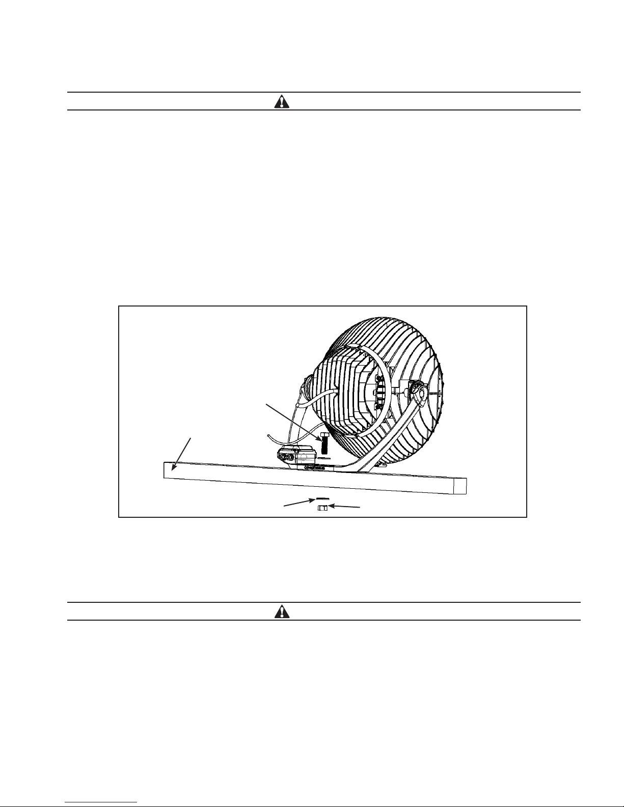
3. Set luminaire in place and install bolt, washers, and nut to securely fasten the fixture mounting bracket to the mounting
structure. Tighten hardware hand tight so that fixture is secure but do not fully torque hardware until aiming is complete.
4. Remove the clear protective film from the front of the lenses, if present.
ote:N Example mounting structure shown for illustration purposes only.
Inverted Mounting
The luminaire hangs from underneath mounting structure.
WARNING
When using inverted mounting, flip the mounting bracket so that the luminaire stays upright. NEVER install the
luminaire upside down. FAILURE TO FOLLOW THIS WARNING MAY LEAD TO LUMINAIRE INTERNAL DAMAGE AND
FAILURE.
1. To install the luminaire underneath a mounting structure, the fixture mounting bracket must first be inverted.
Remove Hex bolt and set screw on each side of the fixture.
Remove Fixture Mounting bracket and flip it so that the bracket faces up.
Reinstall hex bolts and set screws on each side of the fixture.
Figure 2. Standard Mounting
Mounting
Structure
Hex Nut
Hex Bolt
Flat Washer

6EATON IB528002EN Installation instructions rev 20171011
Installation Instructions - Stadium Series
2. Refer to the project photometrics or Installation Drawings to determine luminaire installation locations.
3. For each fixture location, install a luminaire that has the correct lens type. Unless otherwise noted, fixtures that share
the same lens type are identical.
4. Hold luminaire in place and install bolt, flat washers, and nut to securely fasten the fixture mounting bracket to the
mounting structure. Tighten hardware hand tight so that fixture is secure but do not fully torque hardware until aiming is
complete. Ensure when installing that the inverted luminaire is properly supported.
5. Remove the clear protective film from the front of the lenses, if present.
Figure 3. Inverted Mounting
Mounting Structure
Flat Washer
Hex Nut
Hex Bolt
Step 2 – Label The Luminaires (If Required)
For outdoor applications where smaller groups of luminaires are installed on poles, it is not necessary to label the fixtures. If
you are installing fixtures on poles or other applications where labeling is not required, skip this step and proceed to step 3.
For indoor applications where many luminaires are installed in a row along a catwalk, the fixtures are typically labeled to
facilitate identifying each one at a glance from the catwalk.
1. Label each fixture with Luminaire Number as indicated on schedules in the project Installation drawings.
2. Labels shall be white background with black lettering. Text shall be at least 1/4” tall.
3. Affix the label to the mounting bracket in a prominent location, avoiding manufacturer labels. See example location in the
image to the right.
Figure 4. Luminaire Label
Label Here

7
EATON IB528002EN Installation instructions rev 20171011
Installation Instructions - Stadium Series
Step 3 – Make Electrical Connections
WARNING
Never connect the luminaire to an electrical system that is not grounded. Installing a luminaire in an ungrounded
electrical system could allow the metal housing to become energized in the event of an electrical short, resulting in
the risk of electrical shock for anyone who comes into contact with the fixture. FAILURE TO FOLLOW THIS WARNING
MAY LEAD TO DEATH, SEVERE INJURY, OR PROPERTY DAMAGE.
Equipment Required:
Philips screw driver
Electrical splicing connectors. For all outdoor installations, silicone filled water resistant connectors are highly
recommended (i.e. waterproof wire nuts that pass UL ratings).
Control XLR In/Out
Power Whip
Figure 5. Electrical Connections
Power wiring
Wiring connections:
Connect the luminaire power whip to incoming power wires or the plug. See the table below for the color designation.
Luminaire power wire color Designation
Black Line
White Line or Neutral
Green Ground
Table 5. Power wiring connections
WARNING
NEVER connect the bare or green insulation ground wire to the black (HOT) current-carrying or white (NEUTRAL)
supply wire, as this could energize the metal housing and create the risk of electrical shock. FAILURE TO FOLLOW
THIS WARNING MAY LEAD TO DEATH, SEVERE INJURY, OR PROPERTY DAMAGE.

8EATON IB528002EN Installation instructions rev 20171011
Installation Instructions - Stadium Series
WARNING
Do not damage or cut the wire insulation (covering) during installation. Do not permit wires to contact any surface
having a sharp edge, as this may damage the wire insulation and create the risk of electrical shock. FAILURE TO
FOLLOW THIS WARNING MAY LEAD TO DEATH, SEVERE INJURY, OR PROPERTY DAMAGE.
ote:N When power is turned on, the luminaires default to 100% on unless a different control signal is present.
Control Wiring
WARNING
Always turn power to fixture OFF before performing any work on control wiring. Turn transmitters off before working
on main control lines. Performing any work on control connections while fixtures are receiving the signal may
result in transient or fluttering control signals which can cause damage to the luminaire. FAILURE TO FOLLOW THIS
WARNING MAY LEAD TO LUMINAIRE INTERNAL DAMAGE AND FAILURE.
Control Standards
All control work shall conform to ANSI E1.11 – 2008 (r2013), USITT DMX512-A, Asynchronous Serial Digital Data Transmission
Standard for Controlling Lighting Equipment and Accessories. At a minimum DMX cable shall be 1-pair (24AWG, 7x32
Stranding) Twisted (minimum of 4.8 twists/foot), Shielded, minimum of 100 ohms impedance, and <25pF/ft. Capacitance.
WARNING
Use caution when connecting any 24AWG wires as they are more prone to breaking. 24 AWG may be used in
terminal blocks. If wire will be connected with wire nut, wago connector, or other mechanical splices, use 22 AWG
wire.
LANDBURST CONTROLS: Plug in the control lines via the 3-pin XLR whips provided with the luminaire. Use the male
XLR as the DMX input and the female as the DMX output. Use an RDM controller to set the DMX start channel(s) of the
fixture.
Figure 6.
Male DMX In Female DMX
Out

9
EATON IB528002EN Installation instructions rev 20171011
Installation Instructions - Stadium Series
AIRBURST: Using an RDM controller, set the DMX start channel for the luminaire’s wireless controller card (housed in the
front junction box between the LED arrays). The personality setting should populate the channel footprint, if
pre-programmed correctly. Set the Show ID to match the transmitter Show ID.
ote:N In order to use Airburst controls, you must be using a City Theatrical Transceiver and the show id must be set to the
same channel as the show id on the fixtures.
Figure 7.
Wireless Control
Light Series Personality Channel Assignment (Unless
Otherwise Noted)
Stadium Pro 2 Channel Channel 1 Warm LEDs
Channel 2 Cool LEDs
Stadium 1 Channel Channel 1 All LEDs
Table 6. Default Channel Assignment unless otherwise noted
AIRMESH CONTROLS: With airmesh controls, Ephesus will provide the Bluetooth program to connect wirelessly. Simply
open the provided application and connect to each fixture through Bluetooth recognition. Refer to the Airmesh control
manual for more information regarding the mesh network controls.
There are no physical control connections necessary for wireless controls.
Step 4 – Aim the Luminaires
Aiming the luminaires is a critical part of the LED lighting solution to ensure that light is evenly distributed on the playing
surface. There are two basic methods to properly aim a sports venue – Precision Laser Aiming by Coordinates, and
Orient-Tilt.
A. Precision Laser Aiming by Coordinates
Laser aiming is the most effective and preferred technique for aiming Ephesus LED sports lighting. This method
uses a laser mounted to the luminaire to point the fixture at a predetermined point on the playing surface using (X, Y)
coordinates. See the section below “Laser Mount Aiming” for further details on the technique.
Unless otherwise noted, aiming coordinates on Ephesus photometrics or project Installation drawings are based on the
origin (0, 0, 0) placed at center field, court, or ice. For baseball fields, origin is usually the back point of home plate. All
dimensions from that point are in feet along the playing surface unless otherwise noted.
B. Orient–Tilt
With the Orient-tilt method, the installer turns the luminaire according to predetermined angles. This technique is
extremely helpful for pre-aiming fixtures mounted on a cross arm on the ground before the lighting pole is lifted
up and set in place. However, this method is less accurate due to the variances in actual final pole and luminaire
locations and orientations compared to the approximated parameters used in the photometric design.

10 EATON IB528002EN Installation instructions rev 20171011
Installation Instructions - Stadium Series
a. Orient angle: Refers to the direction the luminaire faces in the Z-plane. In other words, mount the luminaire to the
structure but leave the mounting nut slightly loosened to allow the entire fixture to spin about the mounting bolt.
Set the luminaire Orient by rotating the luminaire mounting bracket relative to the mounting structure.
Unless otherwise noted, Orient values shown in Ephesus photometrics or project Installation Drawings are based on 0°
being Plan East. Plan East means 0°is heading to the right side of the sheet as you hold it in front of you, which is not
necessarily geodetic or True East.
b. Tilt angle: Refers to the direction the luminaire faces in the Y-plane. When the luminaire is securely mounted to the
structure so that the mounting bracket does not move but the side Hex and Set screws are loosened, the fixture
may rotate up inside the mounting bracket. Set the luminaire Tilt angle by rotating the fixture housing relative to the
luminaire mounting bracket.
Figure 8. Orient
Orient
180
270
0
90
Orient Angle
Figure 9. Tilt
Tilt
270
90
Tilt Angle
180 0

11
EATON IB528002EN Installation instructions rev 20171011
Installation Instructions - Stadium Series
Minimum tilt angles:
The side set screws will not allow the Stadium to be tilted downward at an angle of more than 60°relative to the horizontal
axis. If the fixture must be tilted down at an angle greater than 600 from the horizontal, remove the side set screws.
If the fixture must be aimed down at less than 20°tilt relative to the vertical axis, use the inverted mounting configuration.
ote:N If a luminaire is installed inverted at low angles in a warm or hot environment, the luminaire lumen output may
decrease to compensate for decreased heat dispersion ability.
If aiming by Orient-Tilt, use an inclinometer and protractor or similar tools to set the luminaires to the correct angles and skip
to Final Aiming.
Laser Mount Aiming
Equipment Required:
Laser or Aiming Tube
Aiming Mount
5/16” Socket Wrench or impact driver
3/16” Hex driver
Torque wrench/driver
1/8” Hex driver (for laser set screws, if needed)
WARNING
NEVER use any power tools on the fixture while the power is on.The vibration caused by power tools may damage
the fixture. FAILURE TO FOLLOW THIS WARNING MAY LEAD TO LUMINAIRE INTERNAL DAMAGE AND FAILURE.
ote:N For outdoor daytime aiming when the laser dot is difficult to see, a piece of rigid tubing may be used in place of the
laser. Outside diameter of tube must be 0.8”-0.87” (ANSI NPS 1/2”) to fit into the Aiming Mount. Slightly smaller
conduit such as 1/2” EMT may be used in the mount with a grommet or other shim only if the shim is evenly
distributed around the tubing to keep it correctly aligned parallel with the top front visor of the luminaire.
WARNING
NEVER point the aiming laser at any person or animal as it can cause permanent damage to eyes. Use laser only for
aiming fixtures as directed. FAILURE TO FOLLOW THIS WARNING MAY LEAD TO SEVERE INJURY.
ote:N Turn off laser while not in use to conserve battery. Have spare battery charged to facilitate the aiming process.
1. Make sure the laser pointer is secured within the mounting apparatus. Tighten to 10 in-lb with a 1/8” hex driver if
necessary.
2. Align the ‘A’ (cut into apparatus) side of the mounting apparatus parallel and front facing to the LED arrays.
3. Insert the aiming mount onto the center heat sink fin until it is fully seated. Aiming mount must be tight against the
fixture because any movement or wiggle in the mount will cause aiming to be inaccurate. Make sure it is seated on the
intersection of the center fins.

12 EATON IB528002EN Installation instructions rev 20171011
Installation Instructions - Stadium Series
4. Slightly loosen the fixture aiming screws just enough to allow the fixture to rotate and tilt. Push on the laser apparatus to
ensure it is tightly pressed onto the heat sinks.
5. Turn on the laser and aim the fixture by targeting the green laser dot at the aiming point. If aiming tube is used, look
through tube and adjust fixture until aiming point is centered in view through tube. Refer to photometrics or project
installation drawings for aiming point coordinates.
ote:N After targeting the aiming point with the laser, turn off the laser to conserve battery life.
6. After aiming is complete, tighten all bolts and screws including hex and set screws on side of fixture and mounting
hardware.
Figure 10. Aiming Laser & Mount
Laser and Mount
Figure 11. Aiming
Aiming Laser
or Tube
Set Screw
Hex Screw
Mounting Hardware

13
EATON IB528002EN Installation instructions rev 20171011
Installation Instructions - Stadium Series
Hardware Torque Value
Mounting bolt/nut 110-125 ft-lbs
Mounting Set bolt (if used) 45-55 ft-lbs
Side Hex screw 60-70 ft-lbs
Side Set screw 35-75 in-lbs
Table 7.
7. Briefly turn the laser back on or re-check view through tube to verify that the luminaire aim did not shift during
tightening.
8. Remove the laser mount from the fixture and proceed to the next luminaire.
Final aiming:
Aiming information is exported from computer lighting simulation software. Since on site conditions may vary from the
computer models, final aiming is usually required to fully achieve desired lighting specifications. Final aiming means deviating
from designed aiming parameters to produce the best outcome on the playing surface. Typically, final aiming only requires
slight adjustments.
1. Verify that all lights are correctly aimed according to the photometric or installation drawings.
2. Measure light levels on the playing surface using a calibrated light meter. Unless otherwise noted, take readings at 3’
above ground, holding the meter out at arm’s length as much as possible, thereby reducing the effect of the shadow
from your body.
ote:N Take horizontal readings by holding the meter face up, parallel with the ground. Take Vertical footcandle readings by
facing the meter at a perpendicular angle to the floor toward the vertical main or vertical end point. These vary based
on venue and sport, but basically refer to the typical locations for elevated main cameras, at the center lines directly
off of the side and off of the end of the playing surface.
Refer to specific project requirements or governing league regulations for more information. For reference, the NCAA lighting
best practices website has grid layouts by sport:
http://www.ncaa.com/news/ncaa/article/2013-11-21/ncaa-best-lighting-practices
3. Review the light measurements and compare the data to project requirements or photometric drawings. If the light
measurements do not meet designed levels, final aiming is required.
ote:N There is no hard and fast rule on how to make final aiming adjustments as it is essentially an art form due to the
propagation and reflection properties of light. A bright spot is usually not caused by one individual luminaire but rather
the additive effect from several luminaires aimed in the same general vicinity.
4. Note the areas of the playing surface that are the brightest and darkest and determine which luminaires are aimed
toward the bright areas and which are aimed near the darkest areas.
5. Re-aim one or a few lights away from the bright areas and closer to the darker areas.
WARNING
During final re-aiming, always minimize the number and size of aiming modifications. Make just one or a few small
adjustments and then re-check light levels. Making too many significant aiming changes may result in failure to meet
specified levels or introducing unwanted results such as glare.
6. Re-measure light levels in areas where adjustments were made and compare new results to project specifications.
7. Repeat steps 5-6 as necessary to meet light level requirements.
Step 5 – Finishing Touches
To complete the installation, verify that all mounting, connection, and aiming work is finished.
Verify all electrical connections are tight and secured. The installer is responsible for the integrity of all connections.
Verify all bolts and screws are tightened and properly torqued.

14 EATON IB528002EN Installation instructions rev 20171011
Installation Instructions - Stadium Series
Straighten up all cabling. Tie down all cables neatly. For all outdoor projects, use UV rated tie wraps and wire
management (to resist UV sun damage and weather harm).
CARE AND MAINTENANCE
All luminaires are prepared with a powder-coated finish. The finish on exterior luminaires may weather over time, depending
on the environmental conditions at the installation site. Proper care of the luminaires will maintain their performance and
appearance.
Follow a regular maintenance schedule to retain optimal light output and thermal performance. Remove any dirt, leaves and
other foreign debris from the luminaire housing. Wipe the optical lenses with a clean, dry, cotton cloth to remove dust and
other contaminants. A non-abrasive polycarbonate cleanser may be used periodically.
WARNING
Do NOT use any abrasives such as car wax, brass cleaners or other polishes or chemicals.These may scratch,
remove, or damage the protective coating, allowing moisture and pollutants to come into contact with the
aluminum, possibly discoloring or pitting the finish.
TROUBLESHOOTING
WARNING
Before performing any work on the luminaire, shut off the power circuit, verify the power is off with a multimeter,
and wait 2 minutes before handling luminaire to avoid electrical shock. FAILURE TO FOLLOW THIS WARNING MAY
LEAD TO DEATH, SEVERE INJURY, OR PROPERTY DAMAGE.
Symptom Possible Cause Corrective Action
No light output
Power is off. Check if circuit power is on.
Bad wire connection. Check input wiring connections.
Control signal set to 0 Verify control signal
Crossed wires or a supply wire is
grounding out. Check wiring connections.
Fuse blows or circuit
breaker trips Improperly sized fuse or breaker Refer to Table 5
Table 8. Troubleshooting Guide

15
EATON IB528002EN Installation instructions rev 20171011
Installation Instructions - Stadium Series

Eaton
1121 Highway 74 South
Peachtree City, GA 30269
P: 770-486-4800
www.eaton.com/lighting
Canada Sales
5925 McLaughlin Road
Mississauga, Ontario L5R 1B8
P: 905-501-3000
F: 905-501-3172
© 2017 Eaton
All Rights Reserved
Printed in USA
Imprimé aux États-Unis
Impreso en los EE. UU.
Publication No. IB528002EN
October 11, 2017
Eaton is a registered trademark.
All trademarks are property
of their respective owners.
Eaton est une marque de commerce
déposée.Toutes les autres marques
de commerce sont la propriété de leur
propriétaire respectif.
Eaton es una marca comercial
registrada.Todas las marcas
comerciales son propiedad de sus
respectivos propietarios.
Product availability, specifications,
and compliances are subject to
change without notice
La disponibilité du produit, les
spécifications et les conformités
peuvent être modifiées sans préavis
La disponibilidad de productos, las
especificaciones y los cumplimientos
están sujetos a cambio sin previo aviso
Warranties and Limitation of Liability
Please refer to www.eaton.com/LightingWarrantyTerms for our terms and conditions.
Garanties et limitation de responsabilité
Veuillez consulter le site www.eaton.com/LightingWarrantyTerms pour obtenir les conditions générales.
Garantías y Limitación de Responsabilidad
Visite www.eaton.com/LightingWarrantyTerms para conocer nuestros términos y condiciones.
This manual suits for next models
1
Table of contents
Other EPHESUS Dj Equipment manuals