EPS 17'hex User manual

Insignia Tent
Instructions
toll free : 800.227.0337 | phone : 303.371.1717 | fax : 303.371.9149
4690 Joliet Street | Denver, Colorado 80239
www.eps-doublet.com
Please read instructions prior to assembling tent.
Proper installation will ensure maximum usage and stability of the structure.
17’hex

2
Caution:
Each installation site must be evaluated prior to installation. Proper securing methods must be determined by the
installer. Some soils require different staking or securing devices other than what is provided with the tent.
Weather is unpredictable; therefore, it is the responsibility of the installer to use good judgement and common sense
setting up your EPS-Doublet Insignia Tent. Insignia Tent should not be left unattended or used during sever weather
conditions. Good judgment must be used to ascertain the severity of weather conditions in determining when to set
up or take down this product. Evacuation of the tent is recommended any time weather is extreme.
Proper safety equipment should be used to ensure a safe set up and take down. EPS-Doublet suggest a careful
examination be make to determine the safety equipment needed, such as hard hats, steel toe shoes, safety glasses
and others materials as required.
Remember: A safe event is a successful event!
Observe the landscape. Make sure tent does not interfere with rain or snow drainage.
The shape of the site, equipment, existing building and landscape can present problems
when setting up the Insignia Tent.
Be careful when setting up tents around trees. Sap and pollen may stain or discolor the
vinyl top. Be aware of any sticks, branches or roots which may scratch or puncture the
tent.
Ensure site is accessible through both set up and removal of the structure.
A site inspection should be made to locate and avoid any overhead or underground water,
electrical, phone or gas lines prior to installation. Trees and overhead power lines can be
potential hazards. Take note and always be aware of all hazards.
Do not attempt to set up structure during thunder storms, high wind conditions or any
other extreme conditions.
Before set up, instruct all participating in set up on all safety procedures. All local safety,
fire and zone regulations must be followed.
Before unloading review the proposed location of the
structure. Take into account the following:
DRAINAGE:
OBSTACLES:
LANDSCAPE:
ACCESS:
HAZARDS:
WEATHER:
SAFETY:
ALL SITE PERSONNEL MUST FOLLOW OCCUPATIONAL
HEALTH AND SAFETY PROCEDURES.

3
Item Part Description Qty Part Number
1 Canopy & Canopy Bag 1 10977
2 Cross Cable 3 112299
3 9’ Legs 6 10591
4Base 6 10514
5 Corner 6 10628
6 Center Pole Assembly 1 10978
7 Eve Tubes 6 10630
10 Lock Pins 6 7834
11 Bolt - 5/16” Nylok 5 4093
Item Part Description Qty Part Number
12 Nut - 5/16” Nylok 5 8369
27 Stakes 3/4” x 34” 12 10666
00 Cable Tool 1
00 Center Pole Lifter 1
14 Flag Pole Extension 1 9523
19 20’ Sliding Wall Cable 4 10673
26 Guy Ropes 4 10689
CA Come Along Wench 1
Items Are Optional
10 (detail)
11 (detail)
12
&
1
2
27
4
5
6
7
14
3
26
Available at local hardware store
00
00
CA

4
Organize all the parts before assembly.
Frame Assembly
1
Assemble the Bases to the 9’ Legs as shown.
2
Assemble the Center Pole as shown. Inner pole has line indicating where it meets lower pole.
3
7Eve Tubes (8)
5Corners (6)
27 Stakes (12)
1Canopy (1)
4Bases (6)
39’ Legs (6)
7Center
Pole
(1)
2Cross Cables (3)
4 3
39’ Legs
11 Bolt
4Base
12 Nut
11 Bolt
12 Nut
6
6Center Pole
11 Bolt
12 Nut
00 Cable Tool
00 Center
Pole Tool

5
Frame Assembly
Assemble frame as shown. Connect all Corners , Eve Tubes and by inserting one into the other as
shown.
4
Attach first Cross Cable diagonally across frame. Hook cable loop over the corner pin on the Corners
as shown in detail.
5
Attach second Cross Cable . Hook one loop over corner pin as shown in step 5.
6
5 7
2
2
7Eve Tube
5Corner
Cable
Pin
5
2Lower Cross Cable
2Second Cross Cable
2Cross Cable
5Corner

6
Canopy Installation
Install the third Cross Cable . Hook one loop over corner pin as shown in step 5. Lift last corner of the
frame upward to shorten the distance and hook the last loop over the pin. Lowering frame will tighten cable.
7
Remove the Canopy from bag. Place Canopy on one side of frame assembly and unfold outwards
towards the other sides.
8
Find center socket and make sure it is facing upwards. If not, flip Canopy over. Grip the center socket and
continue unfolding, pulling towards the center.
9
1
2
Lift
Lift
1Canopy
Canopy
1
Center Socket

7
Lift Lift
Canopy Installation
Attach the Canopy webbing by pulling down on Handle B until webbing Loop A is around Metal Hook C
located on the outside of Corners . Attach webbing to two corners that are adjacent to one another.
10
Continue to pull Canopy toward remaining two corners. Attach the webbing as shown in Step 10. Use
Ground Stake for leverage on final corner as shown in diagram. Lift the opposite corner of the frame
upward to shorten the distance and hook the last loop over the pin. Lowering frame will tighten cable.
11
11
Loop A
Hook C
Handle B
Canopy Canopy
Hook C
Loop A
Handle B
1
Loop A
Hook C
Handle B
Canopy
Ground
Stake
27
27
1
5
Center Socket
1

8
Erecting the Tent
Install four of the six 9’ Legs on an adjacent side. Lift one side of frame and slide assembled
9’ Leg into the Corner . Align holes and secure with Lock Pin .
12
Insert S-Hook at the bottom of the Toggle Rope into the hole in the Base . Tension rope by pulling
toggle down. Tie off slack rope tails. NOTE: Toggle Rope should slide outward from the ring as toggle is
pulled down.
13
3
Corner
5 10
Lock Pin
10
9’ Leg
3
Lock Pin
10
Corner
55
9’ Leg
3
Canopy
4
1Canopy
1
Toggle
9’ Leg
3
Base
4
S-Hook
Toggle
S-Hook
Slide down
to tension
Toggle Rope
should slide
outward from
the ring.

9
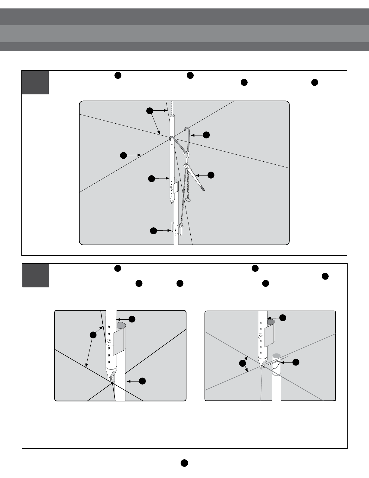
Erecting the Tent
Insert Center Pole through the opening at the center of the Canopy . Lean the Center Pole
against the intersection of the cross cable.
14
Install flag on the Center Pole from the outside of the tent. Be careful when stepping on Canopy
fabric. It is recommended that shoes be removed to prevent staining or damaging Canopy.
15
Slide the Center Pole Tool into the tool holder at the bottom of the Center Pole . Position the Center
Pole with the Center Pole Tool inserted into a vertical position under the Cross Cables .
17
61
600
6
Canopy
1
Center Pole 6
Cross
Cables
2
Center Pole
6
Center Pole
Tool
00
Tool Holder
Install the remaining two 9’ Legs as shown in Step 2 . Lock 9’ Legs in place using the Lock Pins .
16 310
2
10
18 Attach the Cable Tool to the Top Cross Cable . Attach to top of the Come Along Wench to the
Cable Tool and the other hook to the handle of the Center Pole Tool . Raise the Center Pole by
cranking the Come Along Wench until the bottom of the Center Pole is slightly above the cables.
19 Align the Center Pole over the intersection of the three Cross Cables . Lower the Center Pole and
align the notches in Center Pole so they straddle the all three Cross Cables. Secure with Lock Pin .
Remove the Center Pole Tool , Cable Tool and the Come Along Wench .
Lower Cross
Cables
2
Upper Cross
Cable
2
Center Pole
Tool
00
Center Pole 6Come Along
Wench
CA
Cable Tool00
Center Pole6
Cross Cables 2
Center Pole
Tool
00
Center Pole6
Cross Cables 2Lock Pin10
10
6 2
200
00 6
CA00 00
Erecting the Tent

11
Erecting the Tent
Ensure 9’ Legs are aligned and straight. Drive to Ground Stakes through each Base .
20
Secure and tension all Toggle Ropes as shown in Step 13. Tie off slack rope tails. NOTE: Toggle Rope
should slide outward from the ring as toggle is pulled down as illustrated on Page 8.
21
For inclement weather, Guy Ropes are recommended. If needed, install Guy Ropes at this time.
Procedures are on following page.
22
327 4
9’ Leg 3
Base
4
Ground
Stake
27
12
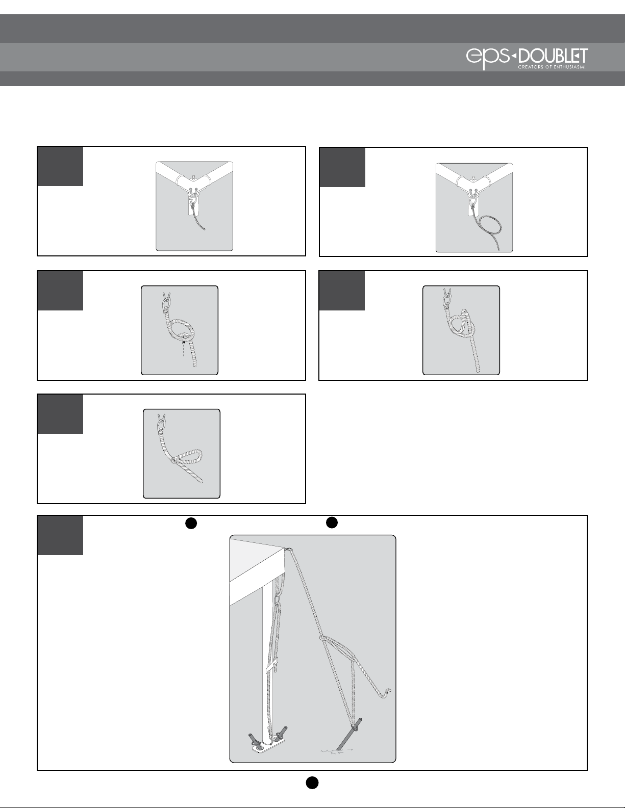
Guy Rope Installation
Snap ring onto corner hook.
1Make a loop about halfway down the height
of tent.
Guy Ropes should always be used in cases of high wind or other inclement weather. Good judgment
must be used to ascertain the severity of weather conditions in determining when to set up or take
down the Insignia Tent.
2
Reach down through loop.
3 4 Make a second loop 4-5” long.
5Pull loop and rope below loop to tighten
knot.
6Drive Ground Stake into ground 5-6’ from Base . Thread rope through stake handle and through
loop. Tie rope to secure.
4
27
13
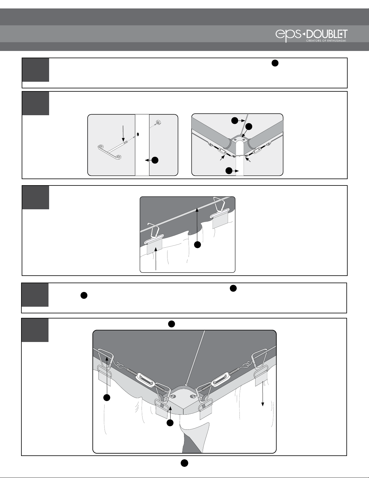
Wall Installation
Before beginning, ensure all Toggle Ropes are evenly tensioned and the Canopy is evenly positioned
on the frame.
1
Attach the walls to the Sliding Wall Cables using clips.
3
Adjust wall so that it hangs evenly along the Sliding Wall Cables . Secure the top of the wall to the
Eve Tube using the straps. NOTE: Type of strap depends on the type of wall. Straps may be side
release, steel buckled or Velcro.
4
Secure the side wall straps to the 9’ Legs . Evenly tension all straps.
5
Sliding Wall
Cable
18
Corner
5
Sliding Wall
Cable
18
Wall Clip
3
Wall Clip
1
7
18
From inside of the tent, install the Sliding Wall Brackets to each post where walls are to be installed. Attach
the Sliding Wall Cables by inserting the Turn Buckle hook into the holes of the Sliding Wall Bracket.
Tension by tightening Turn Buckles.
2
2
Cross Cable
Sliding Wall
Bracket
59’ Leg
Corner
5
Turn Buckle Sliding Wall
Bracket
5
9’ Leg
14
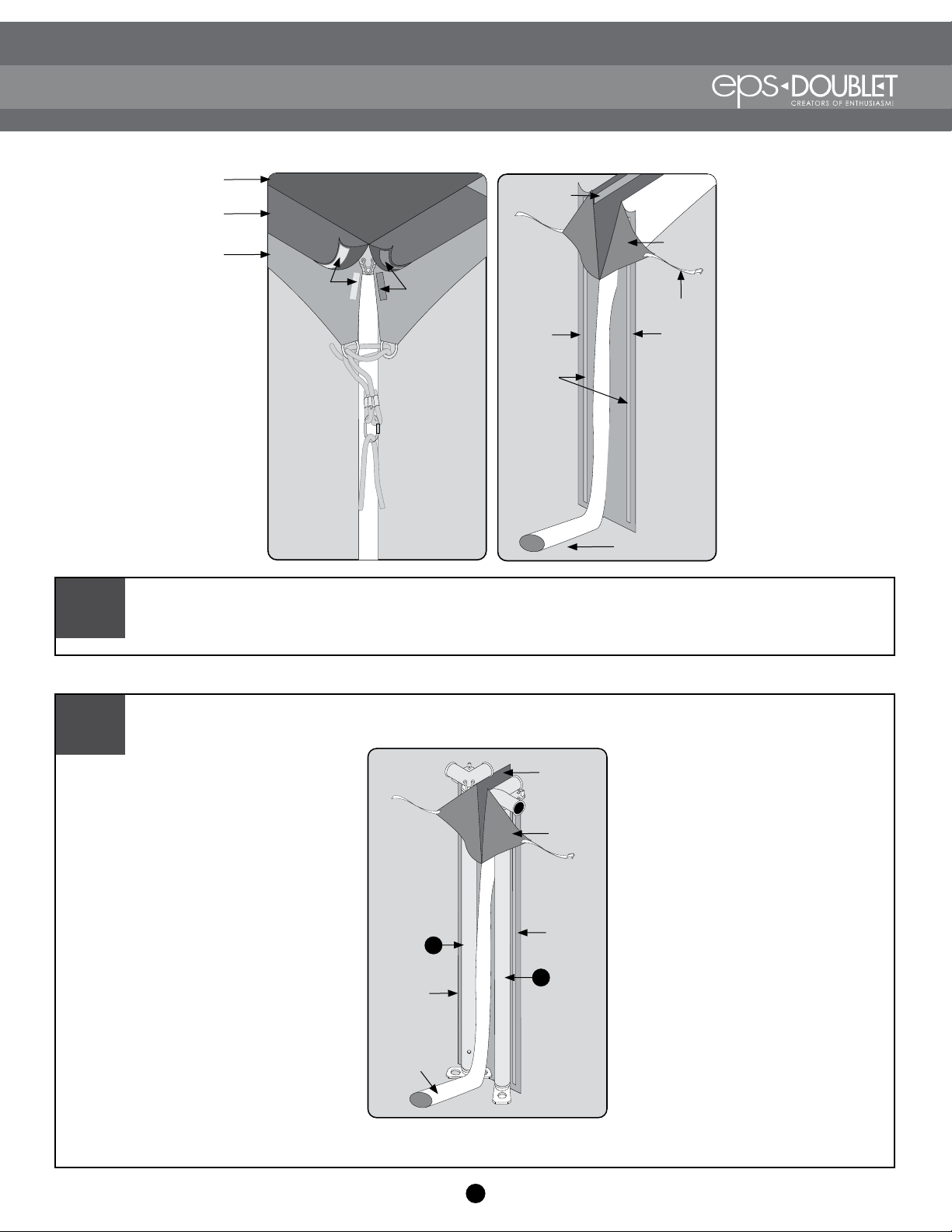
Joiner Installation
Unfold the Joiner. Lay Joiner out between the two tents to be joined. Starting at one tent, slip the joiner
under the Canopy Flab B and fasten the two Velcro strips together. Work down. Maintain a flat, clean seal to
avoid leakage. Repeat this procedure on the other side.
1
Place Joiner Flap (but not the Lapels) and Valance C behind the post. Insert joiner Lapels between the two
posts and spread open.
2
Front Side Joiner Side
Canopy Joiner
Canopy
Canopy Flap
Valance
Velcro Velcro
Downspout
Velcro
Strips
Joiner
Flap
Joiner
Flap
Strap
Lapels
Velcro Strip
Joiner
Flap
Lapels
9’ Leg
3
3
9’ Leg
Valance
Joiner
Flap
Downspout

15
Joiner Installation
Insert Lapel Strap through adjacent front side Valance Ring. Secure the side release buckle. Pull strap to
tighten.
3
From the outside of the tent, fasten both of the front Valances together with the Velcro strips.
4
After the Lapels are in place and secured, fasten the wall straps to the corresponding Posts. Be sure to place
the strap under the toggle ropes. Engage the buckles and pull straps to tighten.
5
From the inside of the tent, beginning at the top, fasten the Velcro strip of the wall to the Joiner Flap. Work
down, insuring the Velcro strips are aligned to provide a good seal.
6
From the outside of the tent, straighten the down spout and any other parts of the joiner to make sure
everything is tightly secured. Adjust the downspouts so water will travel way from the tents. Make sure
water flows away from other structures or traffic within the venue.
7
Valance
Front
Valance Ring
Lapel
Strap

16
Maintaining Your Tent
To clean, spread out canopy on clean surface. Use mild detergent or industrial cleaner that does not contain
bleach. Small rocks and pebbles may create holes in fabric when stepped on. Cleaning the tent while assembled is
recommended. Allow detergent to sit for a while on stubborn areas. Pressure washers are not recommended on tops.
Allow the tent to thoroughly dry before repacking. Dampness may cause mildew or discolor the surfaces. Store your
tent in a clean, dry area.
Characteristics of the Insignia Tent:
MILDEW:
WATER
RESISTANCE:
FLAME
RESISTANCE:
FADING -
OPACITY:
COLD
CRACK:
Remove mildew if detected. There is no way to prevent mold and mildew from growing
once it is prevalent. No tent can be guaranteed not to mildew.
The Insignia tent is make of waterproof materials with welded seams. Some condensation
may occur inside poorly vented tents.
The insignia tent tops and walls are fire retardant. All tent fabric will satisfy ULC-S109,
NFPA 701 and California fire marshal tests.
All Insignia tents are made from fabrics chosen for stability and consistency. Usage and
exposure may affect the finish over time.
The translucent fabrics will remain flexible at temperatures below 0°F. The opaque
fabrics are laminated and therefore become stiffer as the temperature drops. When the
temperature is near 32°F, care should be taken in folding or moving the fabric to prevent
cracking.
CLEANING YOUR TENT:
Popular Tent manuals by other brands

Gazelle
Gazelle T4 Assembly and use instructions

skandika outdoor
skandika outdoor HARSTAD Setup Instruction

Sunjoy
Sunjoy L-GZ1033PST Assembly instructions

Rightline Gear
Rightline Gear Truck Tent quick start guide

toolport
toolport L1-Q2 Series Assembly instructions

Quik Shade
Quik Shade Expedition EX144 owner's manual


