Equalizer International HT125KM Assembly instructions

HT125KM, FA3TM,
FA6TE
FLANGE ALIGNMENT
TOOLS
Operator Instruction Manual
www.equalizerinternational.com
INNOVATION IN ITS MOST FUNCTIONAL FORM


FLANGE ALIGNMENT TOOLS
OPERATOR INSTRUCTION MANUAL PAGE 1
SECTION CONTENTS PAGE NO.
1 INTRODUCTION 2
2 SAFETY INFORMATION 3-4
3 TECHNICAL DATA 5
4 FLANGE MISALIGNMENT DETERMINATION PROCEDURE 6
4.1 LATERAL MISALIGNMENT 6
4.2 ROTATIONAL (TWIST) MISALIGNMENT 7
5HT125KM HAND ALIGNMENT TOOL 8-13
5.1 KIT COMPONENTS 8
5.2 HOW THE HT125KM WORKS 8
5.3 INSTALLATION AND OPERATION 9-10
5.4 EXAMINATION, MAINTENANCE AND STORAGE 11
5.5 PARTS LIST 12
5.6 WEIGHTS AND DIMENSIONS 12
5.7 RANGE OF APPLICATION 13
6FA3TM MECHANICAL FIXED FLANGE AND ROTATIONAL ALIGNMENT TOOL 14-21
6.1 KIT COMPONENTS 14
6.2 HOW THE FA3TM WORKS 14
6.3 INSTALLATION AND OPERATION 15-17
6.4 EXAMINATION, MAINTENANCE AND STORAGE 18
6.5 PARTS LIST 19
6.6 WEIGHTS AND DIMENSIONS 20
6.7 TROUBLESHOOTING 21
6.8 RANGE OF APPLICATION 22
7FA6TE HYDRAULIC FIXED FLANGE AND ROTATIONAL ALIGNMENT TOOL 23-31
7.1 KIT COMPONENTS 23
7.2 HOW THE FA6TE WORKS 23
7.3 INSTALLATION AND OPERATION 24-25
7.4 EXAMINATION, MAINTENANCE AND STORAGE 26
7.5 PARTS LISTS 27-28
7.6 WEIGHTS AND DIMENSIONS 29
7.7 TROUBLESHOOTING 30-31
7.8 RANGE OF APPLICATION 32
INDEX
FAT IM REV 02
28.02.08

FLANGE ALIGNMENT TOOLS
OPERATOR INSTRUCTION MANUAL PAGE 2
The Equalizer HT125KM, FA3TM and FA6TE are aids for use in normal maintenance and
installation procedures, and enable the realignment of misaligned flanges within their
respective working capacities. For example, all of the tools can be used to assist in the
replacement of ring and other types of flange joint. The use of these instructions will
promote safe use, and maximize the service life of the tools. It is recommended that the
operator read the relevant sections of this instruction manual for the particular flange
alignment tool to be used.
1. INTRODUCTION

FLANGE ALIGNMENT TOOLS
OPERATOR INSTRUCTION MANUAL PAGE 3
2. SAFETY INFORMATION
The operator MUST read this manual prior to using the tools.
Failure to comply with the following cautions and warnings could cause equipment
damage and personal injury; read the manual fully!
Read all the following instructions, warnings and cautions carefully. Follow all safety
precautions to avoid personal injury or property damage during system operation.
Equalizer International Ltd cannot be responsible for damage or injury resulting from unsafe
product use, lack of maintenance or incorrect product and/or system operation. Contact
Equalizer International Ltd when in doubt as to the safety precautions and applications. To
protect your warranty, use only good quality hydraulic oil of the grade 32cSt.
Only people competent in the use of mechanical and hydraulic equipment should use these
tools.
In all installations the site safety requirements must be adhered to. ALSO the safety of the
operator, and when present, any assisting personnel, is of paramount importance along with
the safety of others including, when present, the general public.
These instructions are only to cover the safe operation of THE EQUALIZER HT125KM, FA3TM
AND FA6TE FLANGE ALIGNMENT TOOLS, during normal maintenance/installation operations.
All other safety aspects must be controlled by the operation supervisor.
CAUTION:
1. The tools must not be attached to a pressure vessel nozzle
2. The tools must not be attached to a flange joint prior to
misalignment
FLANGE ALIGNMENT TOOLS
OPERATOR INSTRUCTION MANUAL PAGE 4
A CAUTION is used to indicate correct operating or maintenance procedures and practices to
prevent damage to, or destruction of equipment or other property.
A WARNING indicates a potential danger that requires correct procedures or practices to avoid
personal injury.
A DANGER is only used when your action or lack of action may cause serious injury or even
death.
IMPORTANT: Operator must be competent in
the use of hydraulic equipment. The operator
must have read and understood all instructions,
safety issues, cautions and warnings before
starting to operate the Equalizer equipment.
WARNING: To avoid personal injury and
possible equipment damage, make sure all
hydraulic components are rated to a safe
working pressure of 700 bar (10,000 psi)
WARNING: Do not overload equipment. Over-
loading causes equipment failure and possible
personal injury.
The risk of overloading can be avoided by using
the Equalizer Hand Pump, which has its safety
valve set to 700 bar by the factory. If alternative
pumps are used, ensure they are rated at a safe
working pressure of 700 bar (10,000 psi).
CAUTION: Make sure that all system compo-
nents are protected from external sources of
damage, such as excessive heat, fl ame, mov-
ing machine parts, sharp edges and corrosive
chemicals.
CAUTION: Avoid sharp bends and kinks that
will cause severe back-up pressure in hoses.
Bends and kinks lead to premature hose failure.
Do not drop heavy objects onto hoses. A sharp
impact may cause internal damage to hose wire
strands; applying pressure to a damaged hose
may cause it to rupture. Do not place heavy
weights on the hoses, or allow vehicles to roll
over the hoses; crush damage will lead to pre-
mature hose failure.
WARNING: Immediately replace worn
or damaged parts with genuine Equalizer
parts. Equalizer parts are designed to fi t
properly and withstand rated loads. For
repair or maintenance service contact your
Equalizer distributor or service centre.
DANGER: To avoid personal injury keep
hands and feet away from the tool and
workpiece during operation.
WARNING: Always wear suitable clothing
and Personal Protective Equipment (PPE).
DANGER: Do not handle pressurised hos-
es. Escaping oil under pressure can pen-
etrate the skin, causing serious injury. If
oil is injected under the skin, seek medical
attention immediately.
WARNING: Never pressurize unconnected
couplers. Only use hydraulic equipment in
a connected system.
IMPORTANT: Do not lift hydraulic equip-
ment by the hoses or couplers. Use the car-
rying handle or other means of safe trans-
port.
CAUTION: Do not operate the equipment
without lubricating all moving parts as in
section 5.4, 6.4 & 7.4. Use only high pres-
sure molybdenum disulphide grease.

FLANGE ALIGNMENT TOOLS
OPERATOR INSTRUCTION MANUAL PAGE 5
3. TECHNICAL DATA
Tool Description Aligning Force
HT125KM Hand
Alignment Tool
125 kg (275 lbs)
Mechanical Advantage 5 to 1
FA3TM Mechanical
Fixed Flange and Rotational Alignment Tool
3.3 T (33kN)
from 50 ft/lbs (67.8 Nm) of torque
FA6TE Hydraulic
Fixed Flange and Rotational Alignment Tool
6 T (60 kN)
from 10,000 psi (700 bar) of hydraulic pressure
FLANGE ALIGNMENT TOOLS
OPERATOR INSTRUCTION MANUAL PAGE 6
4. FLANGE MISALIGNMENT DETERMINATION PROCEDURE
The tool being used must not be attached to a flanged joint prior to the misalignment
procedure being carried out.
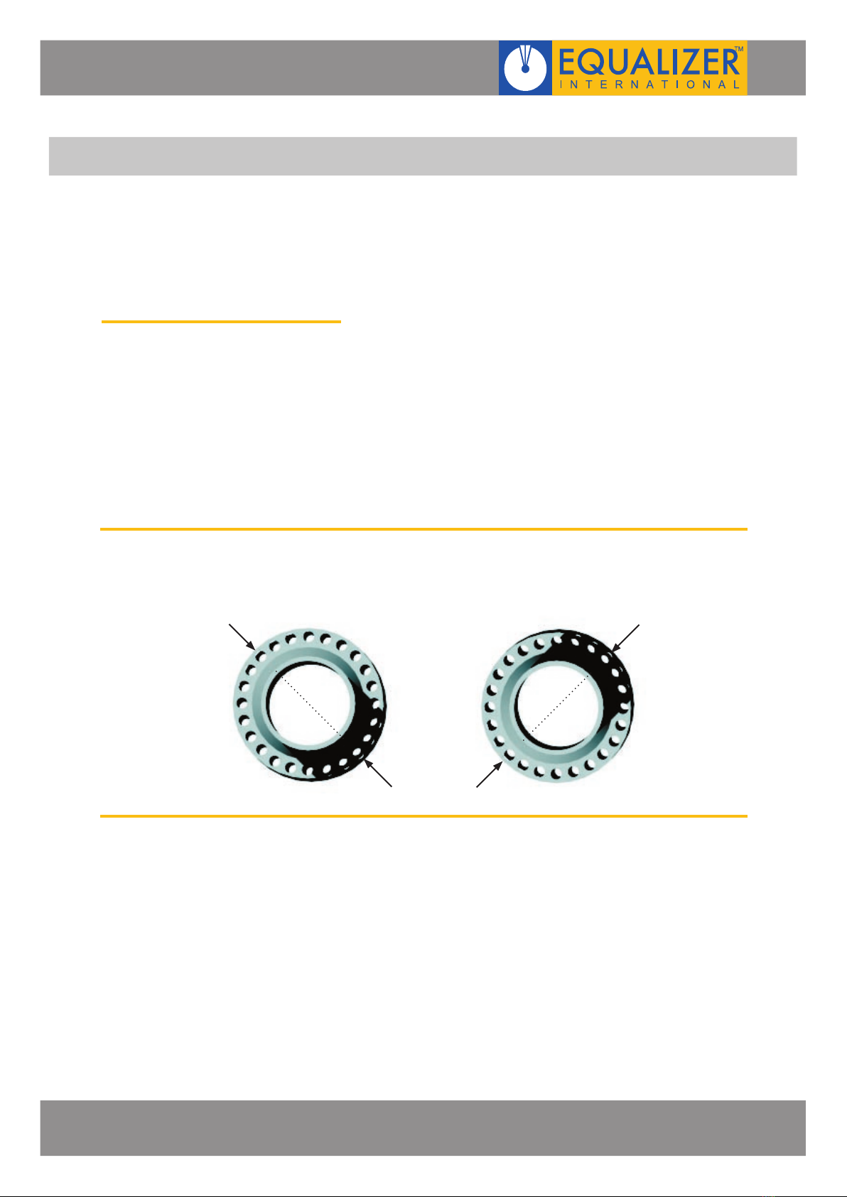
4.1 LATERAL MISALIGNMENT
1. Slacken and remove every second bolt around the flange , continue with this until
misalignment occurs.
A flanged joint, once broken down, may spring out of alignment at any point, or in
any direction around its circumference. Misalignment may not occur until only a few
bolts remain.
2. At this point the direction of any misalignment should become obvious. The
alignment tool being used should be attached at the maximum point of misalignment
(point A or B in the examples shown below) as shown in sections 5.3, 6.3 & 7.3.
POINT A
POINT B POINT A
POINT B
FLANGE ALIGNMENT TOOLS
OPERATOR INSTRUCTION MANUAL PAGE 7
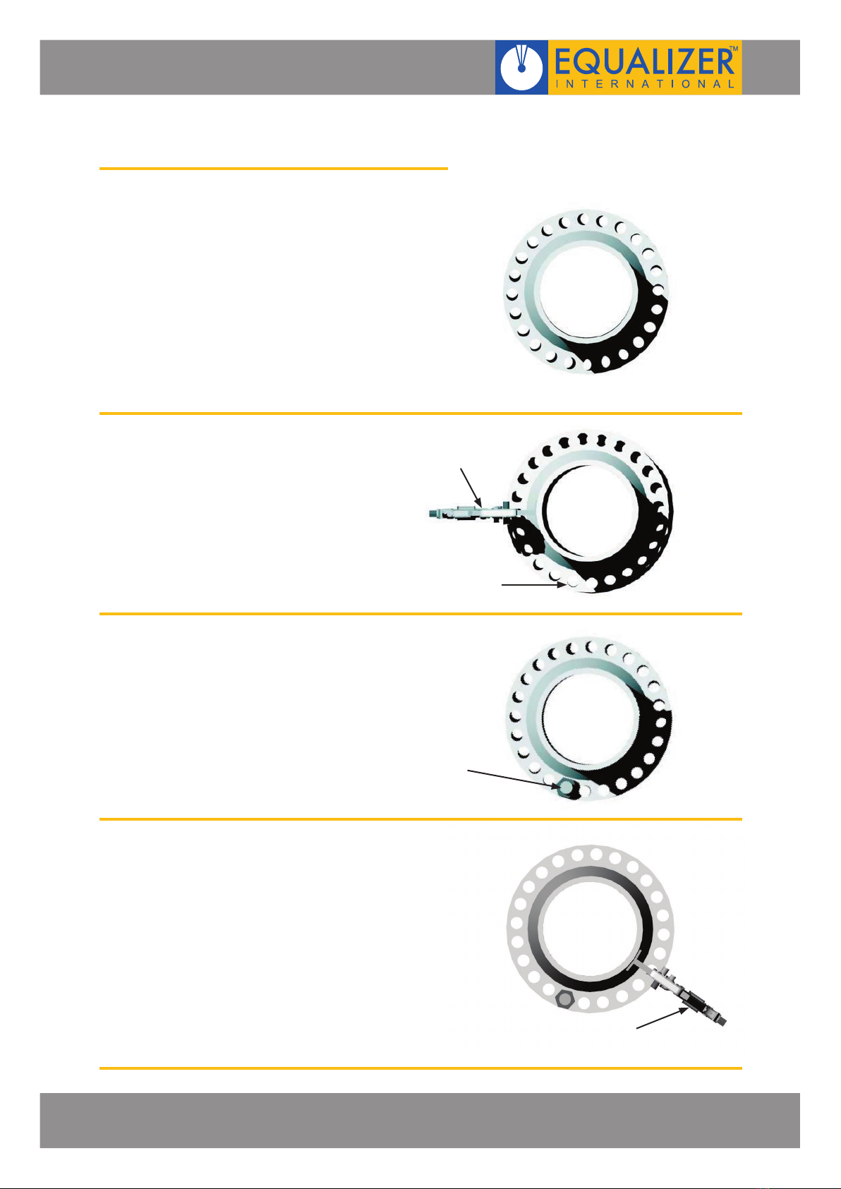
4.2 ROTATIONAL (TWIST) MISALIGNMENT
If the outer circumference of the flanges
are in alignment but the operator is unable
to fit the bolt into any two corresponding
bolt-holes then rotational misalignment may
have occured.
In this case the alignment tool can be
attached to the most accessible point as
misalignment occurs at all bolt-holes to the
same degree.
1. Attach the alignment tool at the
most accessible/convenient point
(as shown in sections 5.3, 6.3 &
7.3) and use it to push the flanges
out of alignment until one pair
of bolt-holes becomes parallel.
2. Insert the bolt into the aligned bolt-
hole and release the alignment tool.
The load will transfer onto the bolt.
3. Repeat steps 1 and 2 at other points
around the flange until all of the
remaining bolt-holes are parallel and
the rest of the bolts can be inserted.
PARALLEL
BOLT-HOLES
BOLT
ALIGNMENT
TOOL
ALIGNMENT
TOOL
FLANGE ALIGNMENT TOOLS
OPERATOR INSTRUCTION MANUAL PAGE 8
5. HT125KM HAND ALIGNMENT TOOL
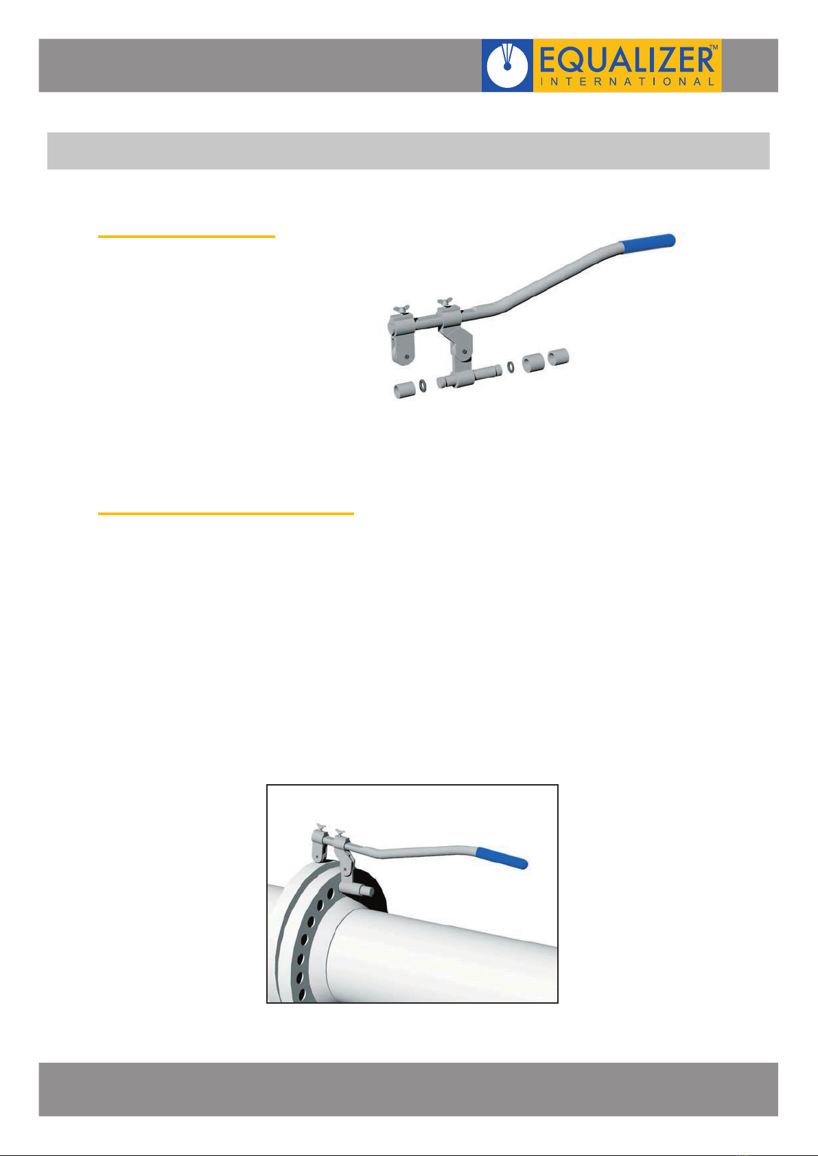
5.1 KIT COMPONENTS
1 x HT125KM Tool
3 x Adaptor Bushes
1 x Instruction Manual
Product Code: HT125KGSTD
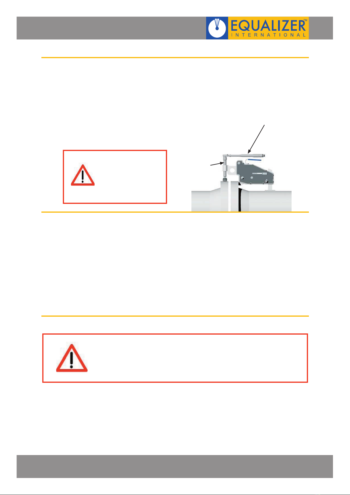
5.2 HOW THE HT125KM WORKS
1. The HT125KM is secured to the lower of the two flanges by fully inserting the lift pin
into the bolt-hole which is parallel with the bolt-hole on the opposite flange. This is
where the misalignment is at its greatest point.
2. The counter-balance is adjusted to the desired distance and the butterfly nut is
tightened at the top.
3. The flange can now be levered up into alignment and the bolts inserted.

FLANGE ALIGNMENT TOOLS
OPERATOR INSTRUCTION MANUAL PAGE 9
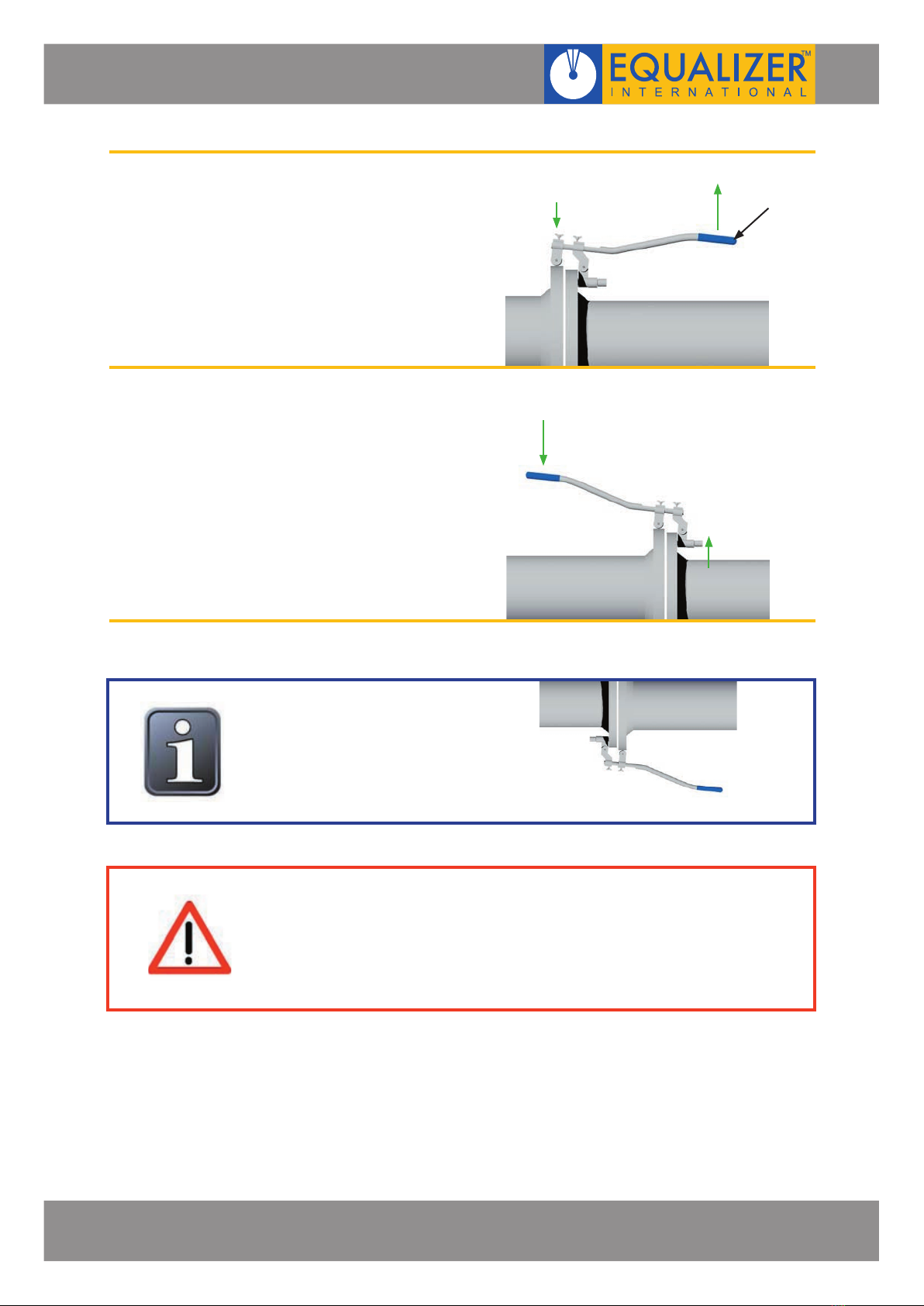
5.3 INSTALLATION AND OPERATION
LIFT MODE:
1. Carry out the Flange Misalignment
Determination Procedure (see
section 4) to determine the points
of maximum misalignment.
In this example the points of
maximum misalignment are at the
top and bottom of the joint.
2. From the three bushes, select the
one which best fits the bolt-hole of
the flange requiring alignment.
3. Attach the selected bush onto the
lift pin.
4. Insert the bush/lift pin into the bolt-
hole on the lower flange.
Adjust the lifting assembly or the
counter-balance and tighten the
butterfly nuts.
POINT OF MAX.
MISALIGNMENT
POINT OF MAX.
MISALIGNMENT
BUSH
LIFT
PIN
COUNTER-
BALANCE
LIFTING
ASSEMBLY
BUTTERFLY
NUT
FLANGE ALIGNMENT TOOLS
OPERATOR INSTRUCTION MANUAL PAGE 10
5. Lift up on the handle and the
counter-balance will push down on
the higher flange bringing the joint
into alignment.
PUSH MODE:
By removing the handle from the
lifting assembly and
counter-balance, the handle can be
re-inserted from the opposite side.
Align the joint by pushing down on
the handle.
Care should be taken not to drop any of the component parts when
removing them from the flange joint. This action will prevent injuries to
either the operator’s lower limbs, or to passers-by.
HANDLE
In this example the joint was
being aligned from the top.
However if access were limited
at the top the alignment could
be rectified from the bottom of
the joint

FLANGE ALIGNMENT TOOLS
OPERATOR INSTRUCTION MANUAL PAGE 11
• On return from each job and before allocation against subsequent work the
completeness of the Equalizer HT125KM kit must be established and items examined
to ensure that they are serviceable
• Any missing or damaged items are to be replaced as soon as possible and prior to the
tool being used again
• Store the HT125KM in a cool dry place and ensure all machined surfaces are greased
• Grease all moving parts regularly
• Ensure the roller remains grit free
5.4 EXAMINATION, MAINTENANCE AND STORAGE
FLANGE ALIGNMENT TOOLS
OPERATOR INSTRUCTION MANUAL PAGE 12
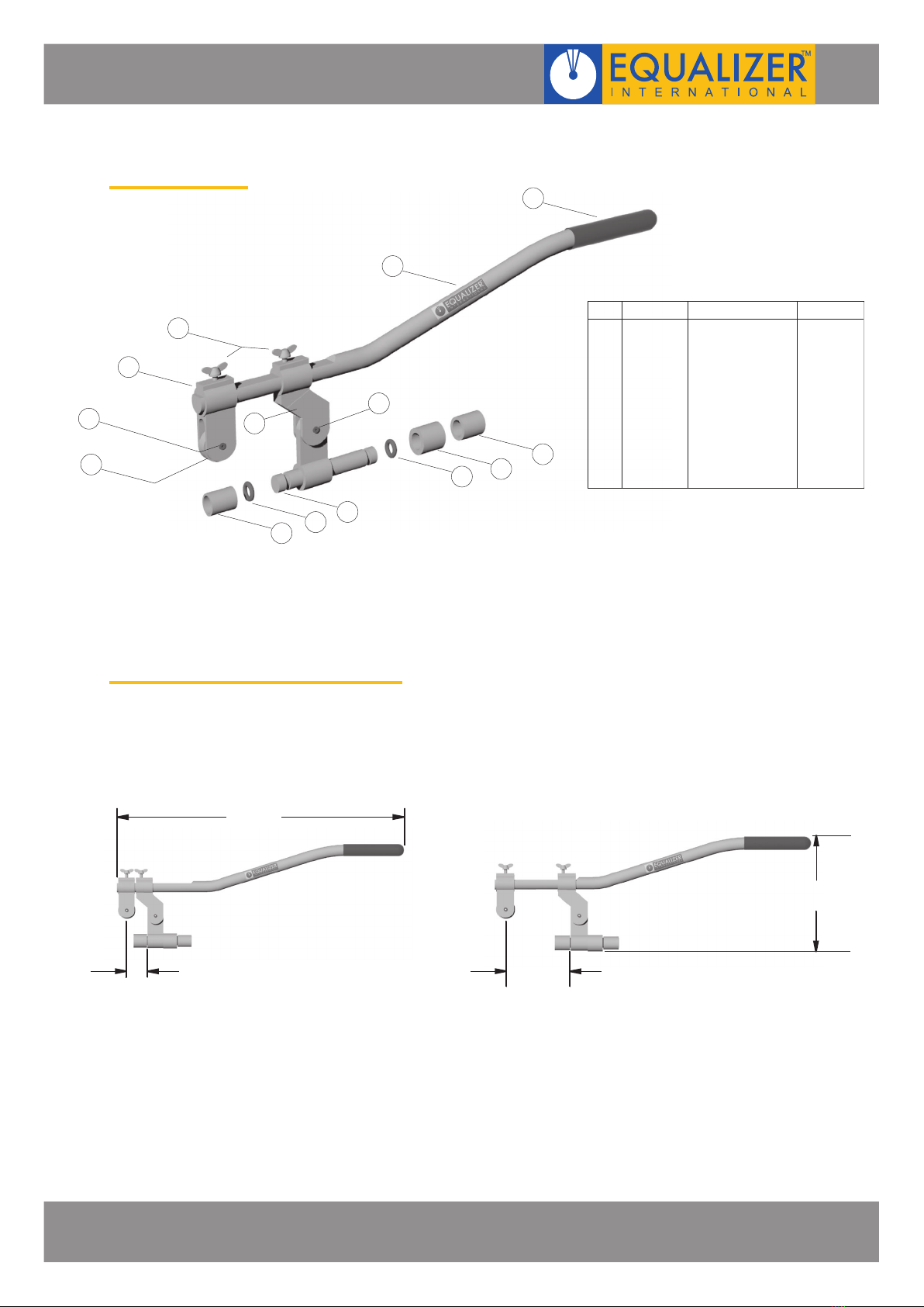
5.5 PARTS LIST
5.6 WEIGHTS AND DIMENSIONS
01
02
04
05
06
07
08
09
10
10 11
12
13
*
*
*
*
*03 01 each
01 each
01 set of 2
01 each
01 each
01 each
01 each
01 each
01 each
01 set of 2
01 each
01 each
01 each
201201-01
200102-01
200901-02
200202-01
200302-01
201102-01
200502-01
200601-01
200402-01
201001-02
200801-01
200701-01
201401-01
HANDLE SLEEVE-BLUE
MAIN BAR
BUTTERFLY NUT
LIFTING ASSEMBLY
COUNTER-BALANCE
ROLL PIN 3/4”
ROLLER
BUSH A
BOLT-HOLE LEVER
“O” RING
BUSH C
BUSH B
ROLL PIN 1/2”
01
02
03*
04
05
06*
07
08
09
10*
11
12
13*
ITEM PART No. DESCRIPTION QUANTITY
*Repair Kit Part No: 201301-01 with Items 03, 06, 10 & 13
33.0 mm
(1.30")
465 mm
(18.25")
88 mm
(3.46")
230 mm
(9.00")
MINIMUM EXTENSION MAXIMUM EXTENSION
TOOL WEIGHT = 2.0 kg (4.4 lbs)

FLANGE ALIGNMENT TOOLS
OPERATOR INSTRUCTION MANUAL PAGE 13
5.7 RANGE OF APPLICATION
DN
PN
6
10
16
25
40
64
100
160
pressure
(psi)
150
300
400
600
900
1500
2500
Pin Only = Ø 17.0 mm (.669”)
Bush A = Ø 21.3 mm (.836”)
Bush B = Ø 24.4 mm (.957”)
Bush C = Ø 27.4 mm (1.07”)
Pin Only = Ø 17.0 mm (.669”)
Bush A = Ø 21.3 mm (.836”)
Bush B = Ø 24.4 mm (.957”)
Bush C = Ø 27.4 mm (1.07”)
TABLE A: RANGE OF APPLICATION on ANSI, BS & API FLANGES
TABLE B: RANGE OF APPLICATION on DIN FLANGES
+
+
1/2
3/4
+
+
+
1
+
+
+
1 1/4
+
+
+
1 1/2
+
2
+
+
+
+
2 1/2
+
3
+
3 1/2
+
4
+
5
6
8
10
12
14
16
25
+
+
+
32
+
+
+
+
40
+
+
+
+
50
+
+
+
+
65
+
+
+
+
80
+
+
+
+
+
100
+
+
+
+
+
125
+
+
+
+
+
150
+
200
+
250
+
300
350
400
FLANGE ALIGNMENT TOOLS
OPERATOR INSTRUCTION MANUAL PAGE 14
6. FA3TM MECHANICAL FIXED FLANGE AND ROTATIONAL ALIGNMENT TOOL
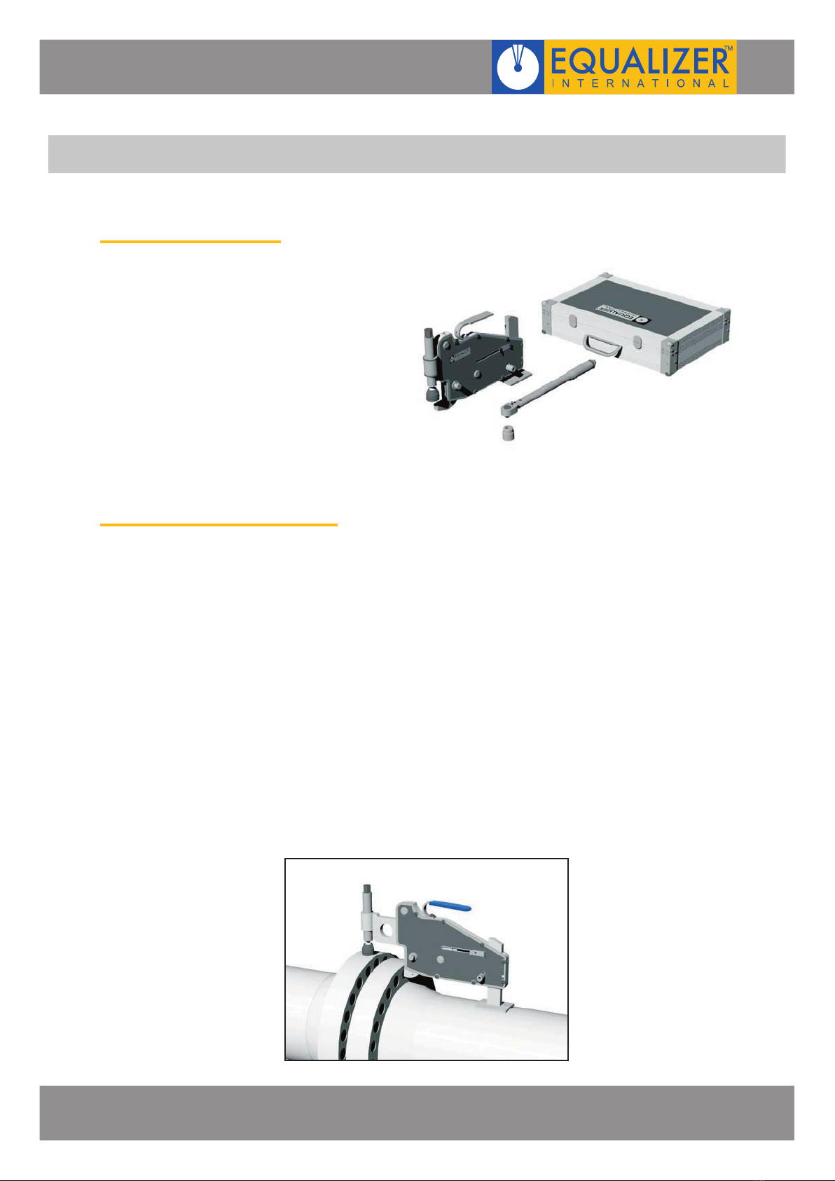
6.1 KIT COMPONENTS
1 x FA3TM Tool
1 x 50 ft/lbs (67.8 Nm) Torque Wrench
with 22 mm Socket
1 x Instruction Manual
1 x Carry-Case with Protective Foam
Inserts
Product Code: FA3TMSTD
6.2 HOW THE FA3TM WORKS
1. The FA3TM is secured to the lower of the two flanges by fully inserting the lift hook
into the bolt-hole which is parallel with the bolt-hole on the opposite flange. This is
where the misalignment is at its greatest point.
2. The drop leg is released onto the pipe while the tool is held up level in the bolt-hole.
3. The wing retaining clip is pulled out to allow the wing to be extended to the required
distance.
4. The screw bolt is turned clockwise until the friction pad comes into contact with the
circumference of the opposite flange.
5. The torque wrench is set to 50 ft/lbs (max), attached to the screw bolt and turned to
screw down on the flange, bringing the joint into alignment.
FLANGE ALIGNMENT TOOLS
OPERATOR INSTRUCTION MANUAL PAGE 15
6.3 INSTALLATION AND OPERATION
Do not pull after the wrench clicks. Use special care at low torque settings.
If the wrench has not been used for some time: operate it several times
at low torque to allow internal lubricant to recoat. When not in use set to
lowest torque setting. Don’t turn handle below lowest torque setting. Your
torque wrench is a precision measuring instrument and should be treated
as such. Clean only by wiping, do not use any type of cleaner which may
affect the special internal lubricant with which this wrench is packed at the
factory.
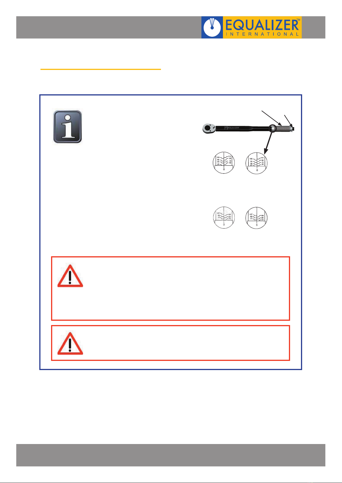
How to use the torque wrench
Balance the wrench in your left hand
and unlock the knurled handle by
turning the locking knob anti-clockwise.
Set the torque amount by turning the
knurled handle - see example 40-46
N/m
1. Turn the handle till 0 on fine scale
reach 40 N/m on base scale
2. To set 46 turn handle till fine scale
reach 6
3. Lock handle by turning the locking
knob clockwise
Install the proper socket and attach to
the tool. Pull handle till you feel and/or
hear the wrench click. Setting of ft/lb
scale is done in the same way as above.
KNURLED
HANDLE LOCKING
KNOB
1. Do not attempt to turn the grip while it is locked
2. Do not turn the grip more than one turn below the lowest scale reading
or above the highest scale reading
Newton Scale (N/m)
40 N/m 46 N/m
(1 on fine scale
= 1 N/m)
Foot Pound (Ft.lb)
70 ft/lb 75 ft/lb
(1 on fine scale
= 0.74 ft/lb)

FLANGE ALIGNMENT TOOLS
OPERATOR INSTRUCTION MANUAL PAGE 16
1. Carry out the Flange Misalignment
Determination Procedure (see
section 4) to determine the points
of maximum misalignment.
In this example the points of
maximum misalignment are at the
top and bottom of the joint.
2. Guide the lift hook into the bolt-hole
at the maximum point of
misalignment.
Release the drop leg onto the pipe
(using the release knob) while
holding the lift hook up level with
the bolt-hole.
3. Pull the wing retaining clip out and
extend the wing to the required
distance.
Rotate the screw bolt onto the
surface of the opposite flange.
Ensure that the tool is sitting
level and that the friction pad on
the base of the swivel is in full and
even contact with the surface of the
opposite flange.
POINT OF MAX.
MISALIGNMENT
POINT OF MAX.
MISALIGNMENT
LIFT
HOOK
RELEASE
KNOB
WING RETAINING
CLIP
WING
SCREW
BOLT
SWIVEL
FLANGE ALIGNMENT TOOLS
OPERATOR INSTRUCTION MANUAL PAGE 17
4. Attach the torque wrench to the
screw bolt and tighten in a
clockwise direction until the joint
comes into alignment.
The torque wrench should be set
at staged increases, e.g. 10 ft/lbs,
20ft/lbs until the maximum
setting of 50ft/lbs (67.8 N/m) is
reached.
5. Once in alignment the bolts may
be inserted and tightened.
After replacing all of the bolts (apart
from the bolt which will go into the
bolt-hole in which the FA3TM is
located), remove the tool by
reversing steps 2 - 4.
Insert the last bolt and tighten.
The torque wrench
will click when the full
50 ft/lbs (67.8 N/m) is
achieved - exceeding
50 ft/lbs will result in
damage to the tool
Care should be taken not to drop any of the component parts when
removing them from the flange joint. This action will prevent injuries to
either the operator’s lower limbs, or to passers-by.
TORQUE
WRENCH
SCREW
BOLT

FLANGE ALIGNMENT TOOLS
OPERATOR INSTRUCTION MANUAL PAGE 18
• On return from each job and before allocation against subsequent work the
completeness of the Equalizer FA3TM kit must be established and items examined
to ensure that they are serviceable
• Any missing or damaged items are to be replaced as soon as possible and prior to the
tool being used again
• Store the FA3TM in a cool dry place and ensure all machined surfaces are greased
• Return all items to carry case when not in use
• Ensure rollers, pins and wing remain grit free and that the rollers rotate freely
• Grease all moving parts regularly:
6.4 EXAMINATION, MAINTENANCE AND STORAGE
1. Place the tool on a flat bench.
2. Using a small flat screw driver, lever
out the end of the spiral clips and
then rotate anti-clockwise and
remove.
3. Remove the pull pin and lift hook,
unscrew the seven side plate
screws, and lift off the side plate.
4. Inspect the roller pin and needle
bearings within the rollers for dirt or
grit. Clean and then smear a small
amount of grease onto the roller pin
and into the needle bearing.
Recommended grease -
Rocol or Sapphire Hi-Load
5. Re-assemble by reversing steps 2-3.
SPIRAL
CLIP
PULL
PIN
LIFT
HOOK
SIDE PLATE
SCREW
SIDE
PLATE
ROLLER
PIN
NEEDLE
BEARING
This manual suits for next models
2
Table of contents
Other Equalizer International Power Tools manuals


