Equipment Technologies APACHE AS1010 User manual

FORM # 580000049
COPYRIGHT 2008
EQUIPMENT TECHNOLOGIES
APACHE
A S 1010 & A S 1210
2008 Owner’s Manual
DO NOT OPERATE THIS EQUIPMENT UNTIL THIS MANUAL HAS BEEN READ AND UNDER-
STOOD. ONLY PROPERLY TRAINED PERSONS SHOULD OPERATE THIS MACHINE.
TM


INTRODUCTION
Dear Valued Customer,
Congratulations on the purchase of your new Apache Sprayer and welcome to
the Apache family of owners. We hope that your new sprayer exceeds your
expectations and gives you years of satisfaction. We invite you to visit us at
www.apachesprayer.com or in person at our plant in Mooresville, Indiana if
you are in the area.
On behalf of all of our employees we thank you for your business.
Yours Faithfully,
Matthew F. Hays
Chief Executive Officer


SPECIFICATIONS
AS1010 AS1210
Tank Capacity 850 gallons (1000 gallons optional) 1200 gallons
Engine 215 Cummins Tier III
655 ft-lb@1500 rpm
275 Cummins Tier III
655 ft-lb@1500 rpm
Transmission Standard: ITL Powershift 6-speed
torque converted
Optional: Funk Powershift 6-speed
torque converted
Funk Powershift
6-speed, torque converted
Speeds ITL 6-Speed
1st 0-5 mph
2nd 0-8 mph
3rd 0-11 mph
4th 0-18 mph
5th 0-29 mph
6th 0-36 mph
Funk Transmission
1st 0-5 mph
2nd 0-8 mph
3rd 0-11 mph
4th 0-18 mph
5th 0-29 mph
6th 0-36 mph
1st 0-5 mph
2nd 0-8 mph
3rd 0-11 mph
4th 0-18 mph
5th 0-29 mph
6th 0-36 mph
Brakes Internal, wet disc self-adjusting
Suspension Front Axle: Center oscillation with independent hydraulic accumulation.
Rear Axle: Patented hydraulic load suspension with compensating anti-sway con-
trol, self-adjusting for diminishing/increasing load.
Crop Clearance 36”, 42”, 48” 48”
Axles Narrow fixed: 88” to 90”, 100” to 101”, 102” -
104”, 105” to 114”. 48” crop clearance only.
Wide adjustable: 120” to 144” (Optional hydraulic
adjust)
Wide adjustable: 120” to
144”. (Optional hydraulic
adjust)
Final Drive Standard: Fairfield all gear drop box
Optional: ITL/JCB planetary gear set Fairfield all gear drop box
Cab ET custom ET custom
Weight 17,329 lbs. (approximate)
Dry weight with poly tank.
20,170 lbs. (approximate)
Dry weight with stainless
steel tank.
Width 144” (12’)
Height 144” (42” crop clearance)
Length 27’
Booms 60’, 75’, 80’, 90’, 100’
60/80, 60/90
Boom Height 14” to 74” (42” crop clearance); 20” to 80” (48” crop clearance)
Wheel Base 173” (14’5”)
Tires Standard Front: 12.4 x 28
Standard Rear: 380/90R46
Optional Front: 380/80R38
Optional Rear: 320/90R46
Standard Front: 380/80R38
Standard Rear: 380/90R46
Turning Radius 17’
Fuel Capacity 100 gallons
Product Pump Hypro 9306S HM1C, hydraulically driven centrifugal pump

OPTIONAL EQUIPMENT
AS1010 Optional Equipment
Please contact your Apache dealer or
www.apachesprayer.com
for more information on optional equipment.
• Narrow axle (48”CC) fixed 88” or 90”, 100-
101”, 102-104”, or 105-114
• 120”-144” manual adjust axles with 36” crop
clearance
• Heavy-duty front axle with 380/80R38 tries,
h.d. spindles, and hubs for all axle spacing
• Hydraulic on the go wheel adjust (not avail-
able on any narrow axle)
• Funk 6-speed power shift transmission
• 1000 gallon poly tank (must get heavy duty
front axle with this tank)
• 850 gallon stainless steel tank
• 1000 gallon stainless steel tank (must get
heavy duty front axle with this tank)
• Raven 4400 Rate controller, radar speed
pickup or drive shaft sensor
• Raven Envisio Pro Controller (must choose
GPS receiver)
• Raven Envizio Plus
• Raven SmarTrax Autosteer
• Raven GPS receivers 200 and 300
• Raven Autoboom PowerGlide Plus (wheel
gauged)
• Raven Autoboom UltraGlide (optical eye)
• Raven Viper Pro Controller
• Raven AccuBoom (automatic boom shut
off)**
• Smucker Injection Foam Marker
• Additional 50 gallon poly rinse tank (rear
mounted)
• Rotoflush, pump pressured (poly tank only)
• Fence row nozzles one side or both
• Hypro chemical eductor
• 5-way nozzle bodies
• Front fenders (not available on 36” CC)
• Rear fenders (not available on 36” CC)
• Auxiliary field light kit (mounts to cab roof)
• Narrow front ties 320/85R38 (for heavy duty
front axle only)
• Narrow rear tires 320/90R50
• Dual rear tires and spacers either 380/90R46
or 320/90R50 (48” CC only)
• Product tank fill 3” (see wet system for more
options on product side)
• Wide tires front, either 480/70R34 or
23.1”x26” R-3 TORC TRAC TL*
• Wide tires rear, either 520/85R46 or 30.5”x32”
R-3 TORC TRAC TL*
* Only for use on 48” crop clearance models.
** Must also choose controller and GPS options
Note: The AS1010 can be ordered with a Funk 6-
speed power shift transmission option. This option
allows for a second hydraulic pump to be
mounted to the transmission for operating an air
boom.

OPTIONAL EQUIPMENT
AS1210 Optional Equipment
Please contact your Apache dealer or www.apachesprayer.com for more information on optional equp-
ment.
• Hydraulic on the go wheel adjust
• Raven 4400 Rate controller, radar speed pickup or drive shaft sensor
• Raven Envizio Pro Controller (must choose GPS receiver)
• Raven Envizio Plus
• Raven SmarTrax Autosteer
• Raven GPS receivers 200 or 300
• Raven Autoboom PowerGlide Plus (wheel gauged)
• Raven Autoboom UltraGlide (optical eye)
• Raven Viper Pro Controller
• Raven AccuBoom (automatic boom shut off)*
• Smucker Injection Foam Marker
• Additional 50 gallon poly rinse tank (rear mounted)
• Rotoflush, pump pressured (poly tank only)
• Fence row nozzles one side or both
• Hypro chemical eductor
• 5-way nozzle bodies
• Front fenders
• Rear fenders
• Auxiliary field light kit (mounts to cab roof)
• Dual rear tires 380/90R46
• Wide tires front, either 480/70R34 or 23.1”x26” R-3 TORC TRAC TL
• Wide tires rear, either 520/85R46 or 30.5”x32” R-3 TORC TRAC TL
• Product tank fill 3” (see wet system for more options on product side)
• New Leader L3020G4 stainless steel spinner box with (Apache dealer must purchase from Highway
Equipment Company directly and mount the box to Apache)
* Must also choose a controller and GPS option

General Information
The graphics and text in this manual generally describe the AS1010 and AS1210 Apache Sprayers.
Apache Sprayers differ by model and by optionally installed equipment. Your Apache Sprayer may not
exactly match the graphics and/or text descriptions in this manual. Please contact your dealer or Equip-
ment Technologies with any questions regarding this manual or the instructions within.

CONTENTS
Chapter 1: Safety Rules
Safety Signals . . . . . . . . . . . . . . . . . . . . .1-1
Safety Rules . . . . . . . . . . . . . . . . . . . . . . .1-1
Training . . . . . . . . . . . . . . . . . . . . . . . .1-1
Preparation . . . . . . . . . . . . . . . . . . . . .1-1
Starting . . . . . . . . . . . . . . . . . . . . . . . .1-1
Seat Belt . . . . . . . . . . . . . . . . . . . . . . .1-1
Operation . . . . . . . . . . . . . . . . . . . . . .1-2
Entanglement . . . . . . . . . . . . . . . . . . . 1-2
Protective Equipment . . . . . . . . . . . . .1-2
Chapter 2: Safety Decals
Left-Side Decals . . . . . . . . . . . . . . . . . . . .2-1
Cab-Mounted Decals . . . . . . . . . . . . . . . .2-2
Engine-Mounted Decals. . . . . . . . . . . . . .2-3
Chassis-Mounted Decals . . . . . . . . . . . . .2-3
Tank-Mounted Decals . . . . . . . . . . . . . . .2-4
Chapter 3: Vehicle Operation
General Guidelines. . . . . . . . . . . . . . . . . .3-1
Pre-operation Check List . . . . . . . . . . . . .3-1
Cab Overview. . . . . . . . . . . . . . . . . . . . . .3-2
Cab Access Ladder . . . . . . . . . . . . . . . . .3-2
Steering Column. . . . . . . . . . . . . . . . . . . .3-3
Fault Code Indicator:. . . . . . . . . . . . . .3-3
Apache Sprayer Console . . . . . . . . . . . . .3-4
Raven 4400 Controller and T-Handle . . .3-6
Fuse Block . . . . . . . . . . . . . . . . . . . . . . . .3-7
Climate Control and Light
Switches . . . . . . . . . . . . . . . . . . . . . . . . . .3-7
Vehicle Lighting . . . . . . . . . . . . . . . . . . . .3-8
AM/FM Radio with
Weather Band and CD Player . . . . . . . . .3-8
CB Radio Knockout . . . . . . . . . . . . . . . . . 3-9
Seat Adjustment . . . . . . . . . . . . . . . . . . . .3-9
Starting and Stopping the Engine . . . . .3-10
Starting . . . . . . . . . . . . . . . . . . . . . . .3-10
Warm-up . . . . . . . . . . . . . . . . . . . . . .3-11
Stopping . . . . . . . . . . . . . . . . . . . . . .3-11
Vehicle Direction and Speed . . . . . . . . .3-12
Neutral. . . . . . . . . . . . . . . . . . . . . . . .3-12
Forward . . . . . . . . . . . . . . . . . . . . . . .3-12
Shifting Gears . . . . . . . . . . . . . . . . . .3-13
Reverse. . . . . . . . . . . . . . . . . . . . . . .3-14
Cruise Control . . . . . . . . . . . . . . . . . .3-14
Towing. . . . . . . . . . . . . . . . . . . . . . . .3-15
Hood Release. . . . . . . . . . . . . . . . . . . . .3-15
Battery . . . . . . . . . . . . . . . . . . . . . . . . . .3-15
Antenna Mounting Plate . . . . . . . . . . . . .3-16
Raven Drive Shaft Speed
Sensor (Optional) . . . . . . . . . . . . . . . . . .3-16
Raven Radar Gun (Optional) . . . . . . . . . 3-16
Axle Adjustment (Manual) . . . . . . . . . . . 3-17
Front . . . . . . . . . . . . . . . . . . . . . . . . . 3-17
Rear . . . . . . . . . . . . . . . . . . . . . . . . . 3-17
Axle Adjustment (Optional)
(Adjust On The Go) . . . . . . . . . . . . . . . . 3-18
Front . . . . . . . . . . . . . . . . . . . . . . . . . 3-18
Rear . . . . . . . . . . . . . . . . . . . . . . . . . 3-19
Optional Equipment . . . . . . . . . . . . . . . . 3-19
Chapter 4: Wet System Operation
Wet System Overview . . . . . . . . . . . . . . . 4-1
Fill Station . . . . . . . . . . . . . . . . . . . . . . . . 4-1
Product Pump and Valves . . . . . . . . . . . . 4-2
Sump Valve . . . . . . . . . . . . . . . . . . . . . . . 4-2
Rinse and Foam Tank . . . . . . . . . . . . . . . 4-2
Second Rinse Tank (Optional) . . . . . . . . . 4-3
Flow Control . . . . . . . . . . . . . . . . . . . . . . . 4-3
Standard Flow. . . . . . . . . . . . . . . . . . . 4-3
Electronic Boom Valves . . . . . . . . . . . 4-3
Raven 4400 Monitor. . . . . . . . . . . . . . . . . 4-4
Apache Precision Fuse Box . . . . . . . . 4-5
Side Console . . . . . . . . . . . . . . . . . . . . . . 4-6
T-Handle . . . . . . . . . . . . . . . . . . . . . . . . . 4-7
Filling Product Tank . . . . . . . . . . . . . . . . 4-11
Filling Rinse Tank. . . . . . . . . . . . . . . . . . 4-11
Operating Booms . . . . . . . . . . . . . . . . . . 4-13
Tilt to Remove Boom from Cradle. . . 4-13
Unfold Booms . . . . . . . . . . . . . . . . . . 4-13
Unfold Boom Tips . . . . . . . . . . . . . . . 4-14
Height Adjustment. . . . . . . . . . . . . . . 4-14
Tilt to Level Boom . . . . . . . . . . . . . . . 4-15
Fold Boom Tips. . . . . . . . . . . . . . . . . 4-15
Fold Booms. . . . . . . . . . . . . . . . . . . .4-16
Tilt to Return Boom to Cradle . . . . . .4-16
Adjust Poly Tank Straps (if equipped)4-16
Spraying . . . . . . . . . . . . . . . . . . . . . . . . . 4-17
Operating Foam Marker . . . . . . . . . . . . . 4-20
Auto Foam . . . . . . . . . . . . . . . . . . . . 4-20
LandMark Injection Foam Marker . . . 4-21
Flushing Product Tank . . . . . . . . . . . . . . 4-24
Flushing Booms . . . . . . . . . . . . . . . . . . . 4-25
Flushing Wet System . . . . . . . . . . . . . . . 4-26
Cleanload Chemical Eductor . . . . . . . . . 4-28
Startup . . . . . . . . . . . . . . . . . . . . . . . 4-28
Loading Liquid or Powdered Chemical into
Hopper . . . . . . . . . . . . . . . . . . . . . . . 4-28
Loading Liquid and/or Powdered Chemical
with Suction Lance . . . . . . . . . . . . . . 4-29
Shutdown . . . . . . . . . . . . . . . . . . . . . 4-29

Chapter 5: Lubrication and Maintenance
General Information . . . . . . . . . . . . . . . . 5-1
Apache Sprayer Service Interval Chart . 5-2
Before Initial Use . . . . . . . . . . . . . . . . . . 5-3
After First 10 Hours. . . . . . . . . . . . . . . . . 5-3
Adjust Boom . . . . . . . . . . . . . . . . . . . 5-3
As Required . . . . . . . . . . . . . . . . . . . . . . 5-5
Inspect Front Accumulator. . . . . . . . . 5-5
Daily . . . . . . . . . . . . . . . . . . . . . . . . . . . . 5-6
Grease Boom. . . . . . . . . . . . . . . . . . . 5-6
Flush Wet System . . . . . . . . . . . . . . . 5-8
Check Tire Pressure . . . . . . . . . . . . . 5-8
Check Engine Oil Level . . . . . . . . . . . 5-8
Check Cooling System . . . . . . . . . . . 5-9
Check Brake Fluid Level . . . . . . . . . . 5-9
Check Transmission Fluid Level . . . 5-10
Check Hydraulic Fluid Level . . . . . . 5-11
Check A/C Compressor Belt . . . . . . 5-11
Every 40 Hours . . . . . . . . . . . . . . . . . . . 5-12
Torque Lug Nuts . . . . . . . . . . . . . . . 5-12
Grease Steering Components . . . . . 5-12
Grease Axle Components . . . . . . . . 5-13
Torque Boom Lead Bolts. . . . . . . . . 5-13
Check Differential Fluid Level . . . . . 5-14
Check Rear Differential for Leaks . . 5-14
Re-Phase Steering Cylinders . . . . . 5-14
After First 100 Hours. . . . . . . . . . . . . . . 5-15
Every 100 Hours . . . . . . . . . . . . . . . . . . 5-15
Grease Driveline Components . . . . 5-15
Check Axle Extension Bolt Torque . 5-16
Adjust Poly Tank Straps
(if equipped). . . . . . . . . . . . . . . . . . . 5-17
Replace Fuel Filter . . . . . . . . . . . . . 5-17
Replace Fuel Separator Filter . . . . . 5-17
Every 250 Hours . . . . . . . . . . . . . . . . . . 5-18
Clean or Replace Engine Primary
Air Filter . . . . . . . . . . . . . . . . . . . . . . 5-18
Replace Differential Fluid . . . . . . . . 5-19
Replace Hydraulic Fluid Filter . . . . . 5-19
Clean Hydraulic Fluid Strainers . . . . 5-20
Every 500 Hours or Yearly . . . . . . . . . . 5-21
Check Accumulator Fluid Level . . . . 5-21
Replace Fuel Filter. . . . . . . . . . . . . . 5-21
Replace Fuel Separator Filter . . . . . 5-22
Replace Planetary Fluid
(AS 1010 Only) . . . . . . . . . . . . . . . . 5-22
Replace Steering Pressure Filter. . . 5-23
Replace Engine Oil and Filter . . . . . 5-23
Replace Transmission Fluid
and Filter . . . . . . . . . . . . . . . . . . . . . 5-24
Recalibrate Raven Radar Gun. . . . . 5-26
Inspect and Repack Wheel
and Inter-Flex Bearings . . . . . . . . . . 5-26
Every Year . . . . . . . . . . . . . . . . . . . . . . 5-27
Adjust Toe-In . . . . . . . . . . . . . . . . . . 5-27
Replace Engine Safety Air Filter . . . 5-28
Winterize Wet System . . . . . . . . . . . 5-28
Replace Cab Recirculating
Air Filter . . . . . . . . . . . . . . . . . . . . . . 5-31
Replace Cab Charcoal
Air Filter . . . . . . . . . . . . . . . . . . . . . . 5-31
Replace Drop Box Fluid. . . . . . . . . . 5-32
Check Front Suspension
Accumulator Charge . . . . . . . . . . . . 5-32
Every 1000 Hours or Yearly . . . . . . . . . 5-33
Clean Transmission Fluid Strainer. . 5-33
Replace Hydraulic Fluid. . . . . . . . . . 5-33
Chapter 6: Cummins Engine Fault Codes
Chapter 7: Torque Value Charts
Fittings. . . . . . . . . . . . . . . . . . . . . . . . . . . 7-1
Bolts . . . . . . . . . . . . . . . . . . . . . . . . . . . . 7-2
Chapter 8: Troubleshooting
Apache Sprayer Troubleshooting Symptoms
and Solutions . . . . . . . . . . . . . . . . . . . . . 8-1
Chapter 9: System Schematics
Hydraulic System . . . . . . . . . . . . . . . . . . 9-1
Electrical System (Sheet 1 of 5) . . . . . . . 9-2
Electrical System (Sheet 2 of 5) . . . . . . . 9-3
Electrical System (Sheet 3 of 5) . . . . . . . 9-4
Electrical System (Sheet 4 of 5) . . . . . . . 9-5
Electrical System (Sheet 5 of 5) . . . . . . . 9-6
Chapter 10: Warranty
Equipment Technologies Warranty Policy10-1

1-1
SAFETY RULES
Safety Signals
Safety is a primary concern in the design and
manufacturing of our products. Throughout this
manual and on the machine potential hazards are
identified by the “Safety Alert Symbol” followed by
a “Signal Word” which indicates the degree of
hazard. The three degrees of hazard are “Dan-
ger”,” Warning”, and “Caution”
“Danger” indicates an imminently hazardous situ-
ation that, if not avoided, will result in death or
serious injury.
“Warning” indicates a potentially hazardous situa-
tion that, if not avoided, could result in death or
serious injury, and includes hazards that are
exposed when guards are removed.
“Caution” indicates a potentially hazardous situa-
tion that, if not avoided, may result in minor or
moderate injury.
Safety Rules
Training
Carefully read and understand this manual and all
safety decals. If the manual or safety decals
become damaged or misplaced, replacements
may be obtained from your dealer or by calling
(317) 834-4500.
Carefully read and understand all non-Apache
Sprayer manufacturer instructions and manuals
supplied with the Apache Sprayer. These include,
but are not limited to the Engine Owner’s Manual,
Sprayer Monitor System Manual, Radio Manual,
Chemical Eductor Manual, Product Pump Instruc-
tions, and other optional equipment.
Do not allow anyone to operate this equipment
without proper instruction.
If you do not understand any part of this manual
and need assistance, see your dealer.
Preparation
Check all hardware, tighten to torque chart speci-
fications shown in the “Lubrication and Mainte-
nance” section of this manual. See “Lubrication
and Maintenance” on page 5-1.
Check all hydraulic hoses and fittings for leaks
and make sure they are in good working condition
prior to starting the machine. Replace any worn or
damaged fittings or hoses. Check hose routing to
prevent damage during machine operation.
Check tires for proper inflation pressure according
to tire manufacturers recommendations.
Starting
Start engine only from operator’s seat, with trans-
mission in neutral and the parking brake set.
Never start engine by shorting across starter ter-
minals.
Seat Belt
Periodically inspect seat belt and seat belt mount-
ing for damage. Inspect belt for cuts, frays, wear,
discoloration, or abrasion. Replace any damaged
parts (see your dealer).
Never operate equipment without seat belt prop-
erly installed.

SAFETY RULES
1-2
Operation
Reduce the chance of machine roll-over:
• Do not operate on steep slopes.
• Do not drive across a slope. Drive up and
down slopes.
• Do not turn down a slope.
• Slow down when turning.
• Keep booms as close to the ground as possi-
ble.
• Drive slowly across rough ground.
• Do not operate on public roads or highways
with product in the product tank.
Always come to a complete stop before reversing
directions.
Do not fold or unfold booms near power lines.
Do not fold or unfold booms while the vehicle is
moving over 5 mph.
Secure any loose items in cab. Items that are
unsecured may cause injury in case of a vehicle
roll-over.
Do not allow riders in the cab or on the Apache
Sprayer.
Entanglement
Keep hands, feet, hair, and clothing away from all
moving parts. Wear relatively tight and belted
clothing while operating or repairing machine.
Protective Equipment
Always wear clothing appropriate to the job.
When handling chemicals wear long sleeves and
pants, goggles, and gloves. If necessary wear a
respirator when handling chemicals. Remove or
clean contaminated clothing before entering the
cab.
Always wear safety glasses when repairing
machine.

2-1
SAFETY DECALS
Left-Side Decals
NOTE
For 12.4X28” tires:
Torque wheel bolts to
180 foot pounds.
NOTE
For 38” tires:
Torque wheel bolts to
315 foot pounds.

SAFETY DECALS
2-2
Cab-Mounted Decals
SAFETY DECALS
2-3
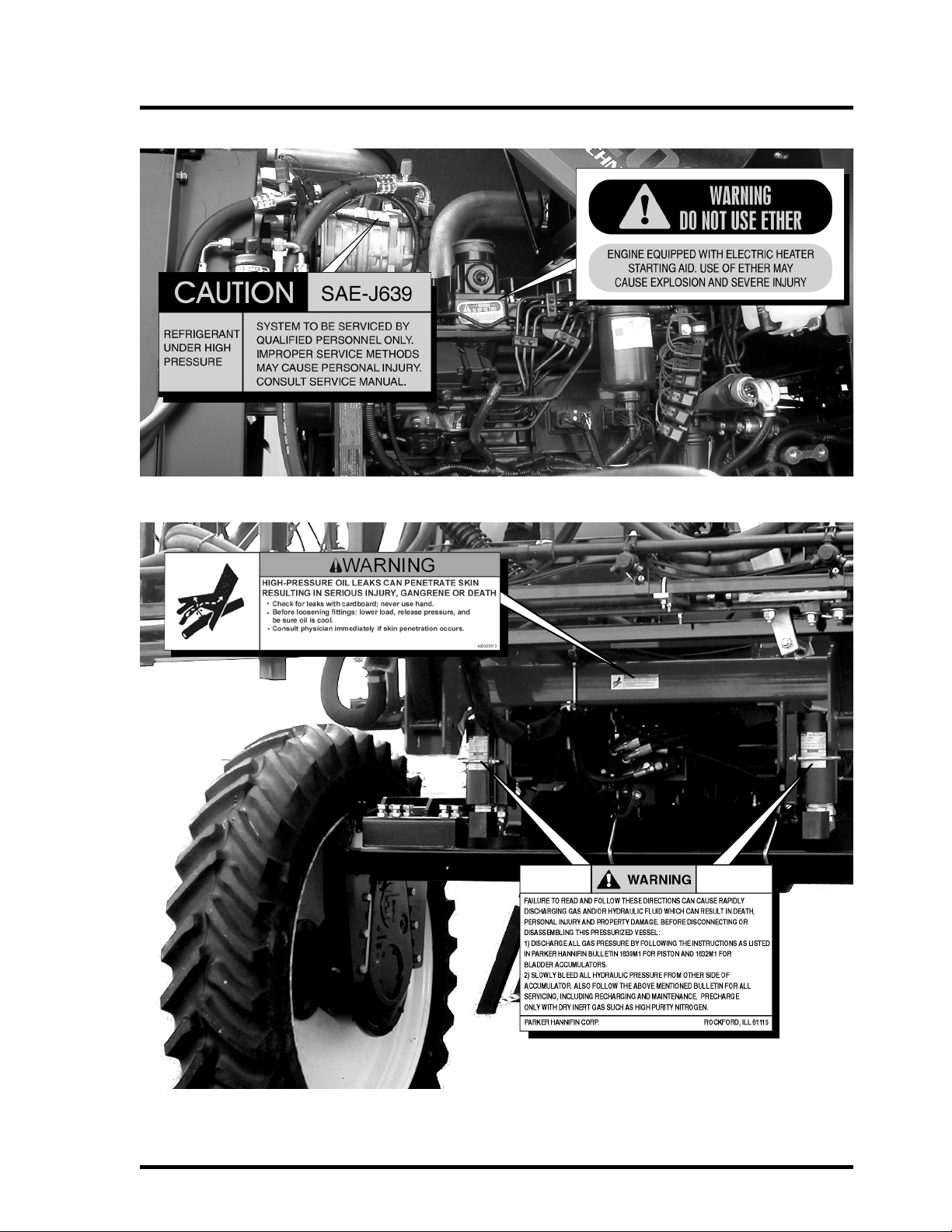
Engine-Mounted Decals
Chassis-Mounted Decals
SAFETY DECALS
2-4
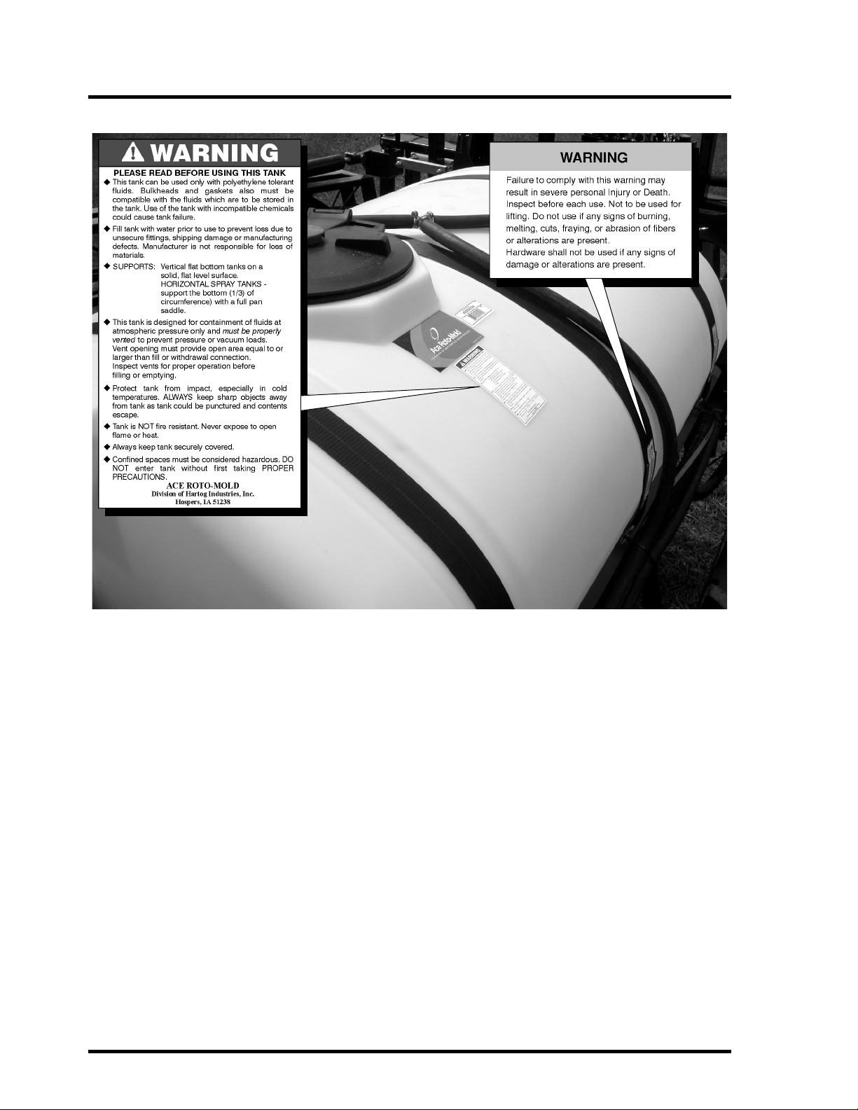
Tank-Mounted Decals

3-1
VEHICLE OPERATION
General Guidelines
Carefully read and understand this manual and all
safety decals. If the manual or safety decals
become damaged or misplaced, replacements
may be obtained from your dealer or by calling
(317) 834-4500.
Do not allow anyone to operate this equipment
without proper instruction.
If you do not understand any part of this manual
and need assistance, see your dealer.
Pre-operation Check List
• Read and understand the owner’s manual
before operating the Apache Sprayer.
• Review and follow all safety rules and safety
decal instruction. See “Safety Rules” on
page 1-1. See “Safety Decals” on page 2-1.
• Check that all safety decals are installed and
in good condition. Replace if damaged.
• Check that all shields and guards are properly
installed and in good working condition.
Replace if damaged.
• Check that all hardware is properly installed
and secured.
• Check area for bystanders and obstruction
before operating.
• Check that all hydraulic hoses and fittings are
in good condition and not leaking before start-
ing tractor.
• Check that hoses are not twisted, sharply
bent, kinked, frayed, or pulled tight and are
not rubbing. Replace any damaged hoses
immediately.
• Make sure seat belt is in good condition.
• Check tires for proper inflation pressure
according to specifications on the back cover
of this manual. See “Check Tire Pressure” on
page 5-8.
• Check oil level in engine prior to starting. Add
oil as needed according to specifications on
the back cover of this manual. See “Check
Engine Oil Level” on page 5-8.
• Check fluid level in transmission. Add fluid as
needed according to specifications on the
back cover of this manual. See “Check Trans-
mission Fluid Level” on page 5-10.
• Check fluid level in differential, gearboxes,
and/or planetaries prior to starting. Add fluid
as needed according to specifications on
back cover of this manual. See “Check Differ-
ential Fluid Level” on page 5-14.
• Check coolant level. Add coolant as needed
according to specifications on back cover of
this manual. See the engine manufacturer’s
manual for details.
• Check hydraulic fluid level in reservoir. See
“Check Hydraulic Fluid Level” on page 5-11.
• Check tank straps on poly product tank to
make sure they are tight.
VEHICLE OPERATION
3-2
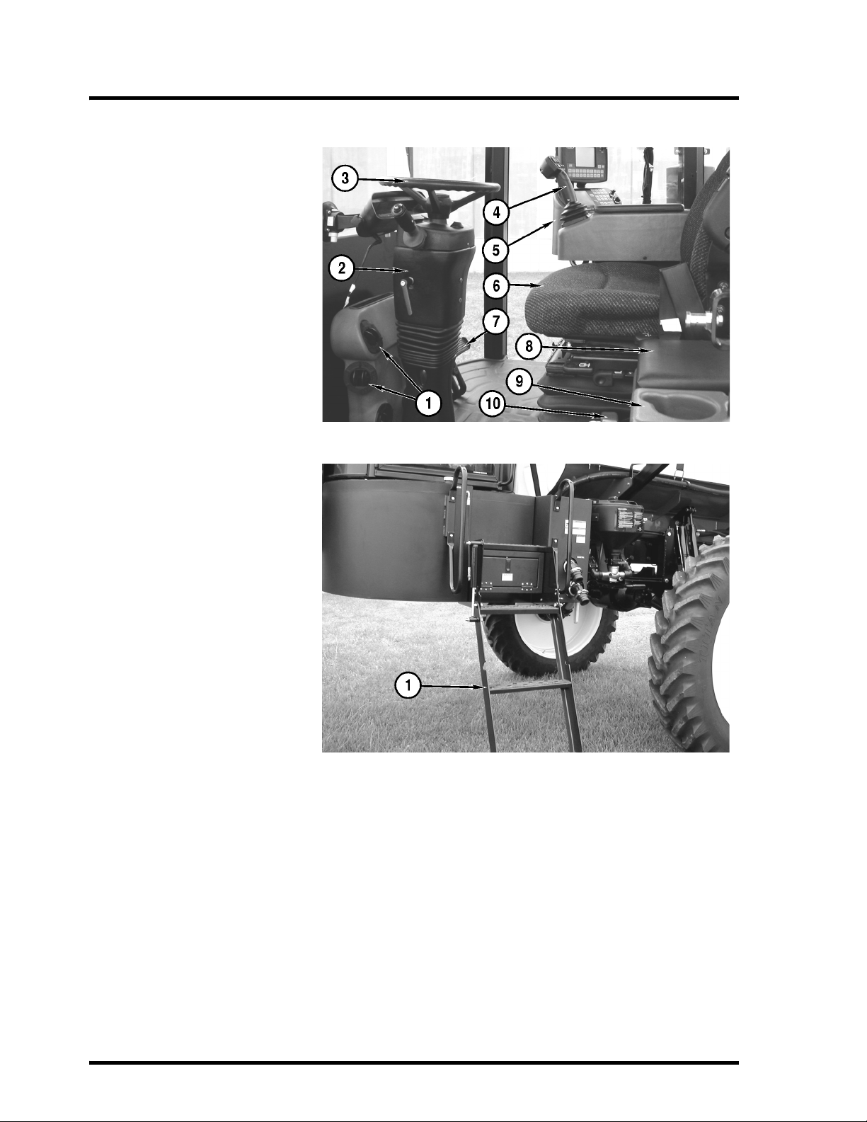
Cab Overview
1. Air vents
2. Steering Column
3. Steering Wheel
4. T-Handle
5. Side Console
6. Air Seat
7. Vehicle Brakes
8. Padded Storage Unit
9. Cup Holder
10. Fire Extinguisher
Cab Access Ladder
1. Access Ladder
The cab access ladder is
automatically actuated by the
parking brake switch. When
the parking brake is applied,
the ladder folds down. When
the parking brake is released,
the ladder folds up.

VEHICLE OPERATION
3-3
Steering Column
1. Adjustment Lever
Turn the lever counter-clockwise to
release the column. Set the tilt and tele-
scope to the desired position. Turn the
lever clockwise to lock the column.
2. Hazard Flasher Button
3. Steering Wheel
4. Key Switch
Shown in “OFF” position. See Starting
and Stopping the Engine for more details.
5. Turn Signal Lever
Push lever up for right turn signal, push
down for left turn signal.
6. Windshield Wiper Switch
Turn lever to the “I” position for low speed
wiper. Turn lever to the “II” position for
high-speed wiper.
7. Windshield Washer
Push ring to operate washer.
8. Horn Button
Push to sound horn.
Fault Code Indicator:
1. Fault Code Indicator on Console
When a fault code is logged, the ET logo
will disappear on the right side of the con-
sole display and one or more of the fol-
lowing fault codes will appear:
• Stop Engine
• Check Engine
• Water In Fuel
• Wait To Start
• Water Temperature
• Failed Fuse F11
• Low Oil Pressure
• Change Air Filter
• High Hyd Temp
• High Trans Temp
• Low Coolant
•ECUFailure
• SPN 00000 FMI 00
Refer to Fault Codes in the Maintenance Section; See “Cummins Engine Fault Codes” on page 6-1.
VEHICLE OPERATION
3-4
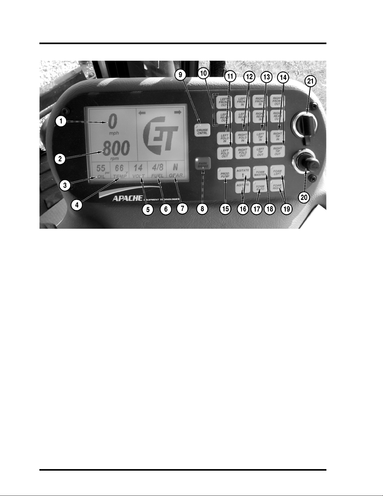
Apache Sprayer Console
1. MPH Readout
2. Engine RPM
3. Engine Oil Pressure
4. Engine Water Temperature
5. Voltage Level
6. Fuel Level
7. Direction & Gear Indicator
8. Park Brake Switch
9. Cruise Control Master Switch
10. Axle Hydraulic Adjust Switches In & Out
(Optional)
11. Left Boom Fold In & Fold Out
12. Right Boom Fold In & Fold Out
13. Left Boom Tip In & Fold Out
14. Right Boom Tip In & Fold Out
15. Product Pump On/Off Switch
16. Agitation Pressure Increase & Decrease
17. Foam Master On/Off Switch
18. Foam Auto On/Off
19. Turn Foam Drop On for Right Side
& Left Side
20. Cigarette Lighter
21. Auxiliary Power Outlet
This manual suits for next models
1
Table of contents
Popular Paint Sprayer manuals by other brands

Clarke
Clarke AP8GFM Operation & maintenance instructions

Smith Performance Sprayers
Smith Performance Sprayers S103E use and care manual

Sagola
Sagola Junior 140 instruction manual

ASM
ASM Zip-Spray 2300 Plus Hi-Boy Operation

Smithco
Smithco Spray Star 3182 Operator's manual

Graco
Graco RentalPro 230PC HDR Operation, parts


