TOPMAQ SX-ST60A User manual
Trolley Electric Sprayer
Model: SX-ST60A
SX-ST80A SX-ST100A
SX-ST80B SX-ST100B
User’s Manual
This manual is a part of the Sprayer, please keep it properly! In order
to better use and maintain this product, please read this manual carefully
before use. If you have any questions, please contact the dealer.
The Sprayer can only be operated, maintained and repaired by
personnel who are familiar with the characteristics of the Sprayer and
have relevant safety operation knowledge.
The manufacturer shall not be held liable for the reduction of
reliability, damage of sprayer or personal injury caused by unauthorized
restructuring of the Sprayer.
Due to product updating, the contents of this manual are subject to
change without prior notice.
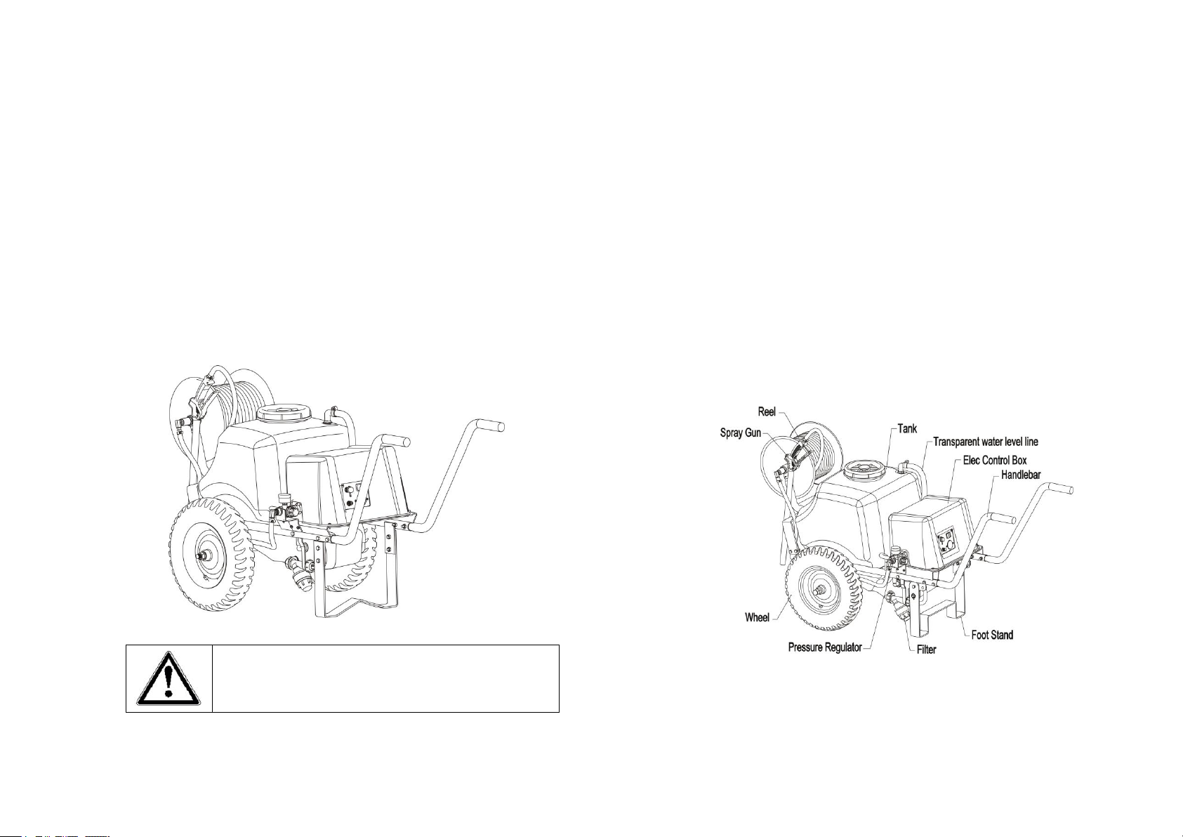
I. Product Overview
1. Comes with a 12V, 100W high power DC electric diaphragm pump,
with maximum working pressure of 10bar, plus overload protection
function, contributing to high pressure, large flow, strong power and
stable performance.
Please read the manual carefully prior to
operation and keep it for future reference!

2. Long boom high-pressure adjustable spray gun, with high strength
engineering plastic body allowing for high pressure spraying and
comfortable grip; with a rotary nozzle offering optional mist/columnar jet
spraying of good atomization performance and far range up to 7m. The
90° spraying angle copper nozzle is wear resistant to ensure extended
service life.
3. The 30m reinforced high-pressure hose allows for long-distance
operation, coupled with a hand-operated hose reel to ensure tidy and
convenient collection.
4. 38Ah high capacity lead-acid power battery allows for continuous
operation up to 4 hours.
5. Designed with a hydraulic adjustment device, with pressure display, to
increase/decrease the working pressure to meet the operation demands.
6. Comes with a trolley frame of double beam and big wheel hub, 4-layer
rubber inflatable engineering tire, to ensure wear-resistance, anti-skid,
shock absorption, easy obstacle crossing, labor-saving push-pull and
flexible steering.
7. The spray tank is made of premium high-density polyethylene under
multi-point wall thickness process control to ensure uniform wall
thickness, good strength, corrosion/aging resistance. The large-size inlet
and drain outlet allow for easy refilling and cleaning.
8.Designed with an external filter of corrosion-resistant PVC to ensure
easy disassembly and cleaning . Its transparent housing makes dirt
visible.
9. Transparent liquid-level display with the help of a floating ball.
10. The spray parts are modularized. You can either chose a high
pressure spray gun with strong targeting performance, and far distance,
or a folding spray wand with large spraying range.
II. Technical parameters
III. Description of safety signs
Caution!
Mind width limit
Crush
hazards.Mind
your hands
Model
SX-
ST60A
SX-
ST80A
SX
-
ST100A
SX-
ST80B
SX
-
ST100B
Capacity of spray tank
60L
80L
100L
80L
100L
External dimension
1440×710
×830
1520×740
×865
1520×740
×865
1520×710
×865
1520×710
×865
Sprayer weight
54.4
56.5
58.5
55.8
57.5
Battery
12V38Ah
Working voltage
12V
Working current
8A
Hose
Specifications
Ø8.5×Ø16
Length
30m
Pump
Type
Diaphragm pump
electric
motor
Power
100w
RPM
2900rpm
Rated pressure
10bar
Pressure limiting
pressure
13bar
Inhalation
volume
7L/min
Charger
input
AC100-240V 2A
output
DC14V 5.0A
Misting
Spray angle
90 Degrees
flow
1.45L/min
Jetting
range
7M
flow
3.3L/min(5bar)
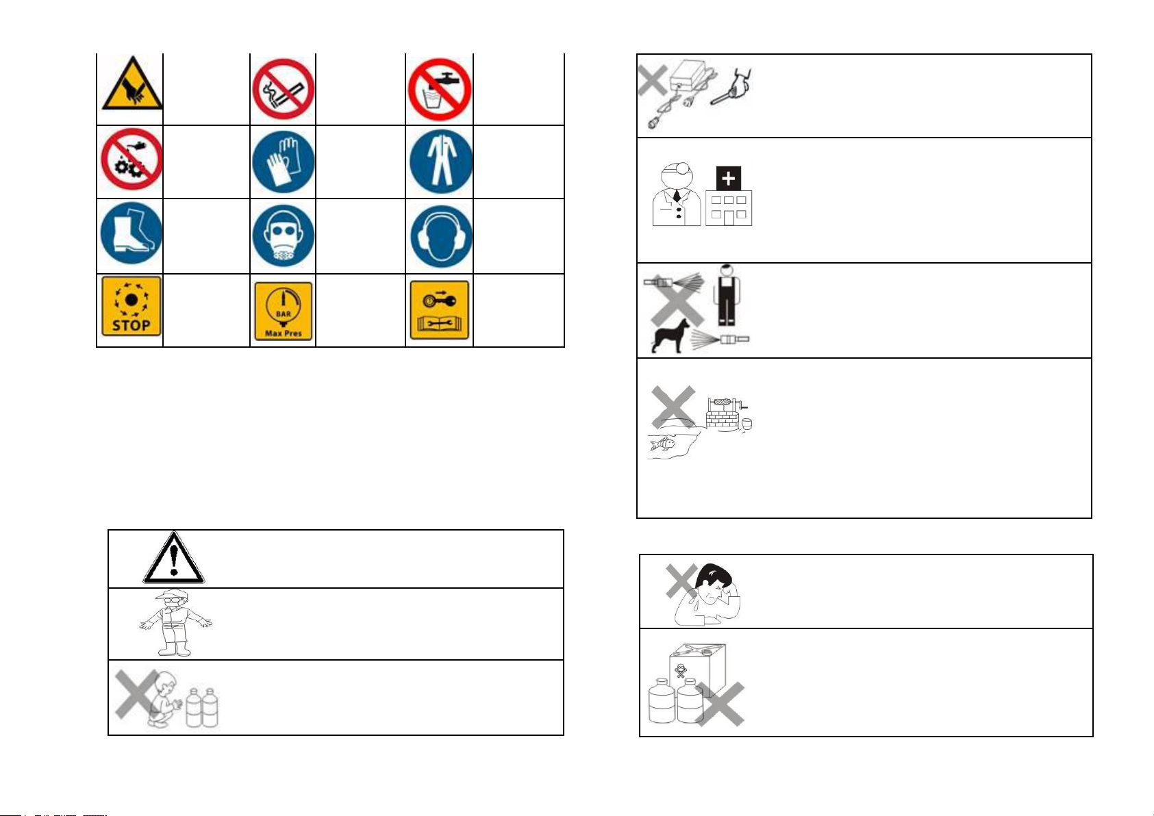
Injury hazards.
Mind your
hands
No Smoking
No drinking
No refuel
during
operation
Wear
protective
gloves
Wear protective
clothing against
pesticide
penetration
Wear
waterproof
rubber shoes
Wear goggles
and masks
Wear ear
protection
STOP alert
Maximum
working
pressure
Refer to the
manual for
operation &
maintenance
IV. Precautions
●while strictly observing the safety operation rules in the Manual,
you are required :
1.Do not use special working fluid;
2.When handling pesticides, follow the safety instructions provided
by the pesticide manufacturer.
DANGER
Please read the manual carefully before operating
the Sprayer and follow the instructions and safety
rules during operation.
In operation, you must wear a mask, a work cap, a
protective clothing, waterproof gloves, rubber
boots and other suitable clothing for operation.
Warehousing and storage of pesticides. Keep out
of reach of children. The safety instructions
provided by pesticide manufacturers should be
strictly followed in the treatment of pesticides.
It is forbidden to repair the charger by non
professionals. If there is any fault, please contact
the dealer.
In case of inhaling the poison, leave the poisoning
environment as soon as possible, move to a
well-ventilated place and lie down for a rest; If your
skin is contaminated, rinse with clean water
immediately; in case of ingesting by mistake, use
clean water or warm salt water to induce vomiting,
before going to the hospital as soon as possible.
During operation, it is never allowed to spray at
people or animals, or operate against the wind.
The unused residual chemicals shall not be
poured into the field, ground or river. It shall be
stored in a special chemical bottle and brought
back safely. Empty chemical bottles and bags
shall either be collected and handed over to the
original manufacturer for centralized disposal, or
buried in a remote area with very deep
underground water , very small rainfall , and far
away from the living area and water resources.
Warning
Persons affected by fatigue, poor health, injury,
pesticide allergy or during pregnancy shall never
engage in pesticide spraying. Alcohol drinking
immediately after the spraying is prohibited.
Never use strong acid, strong alkaline, and other
inflammable solutions. Never use highly-toxic and
highly-persistent pesticide for pest control of
vegetables, melon crops, fruit trees, tee, herbal
medicines etc. And the harvesting time after
pesticide application shall be long enough.
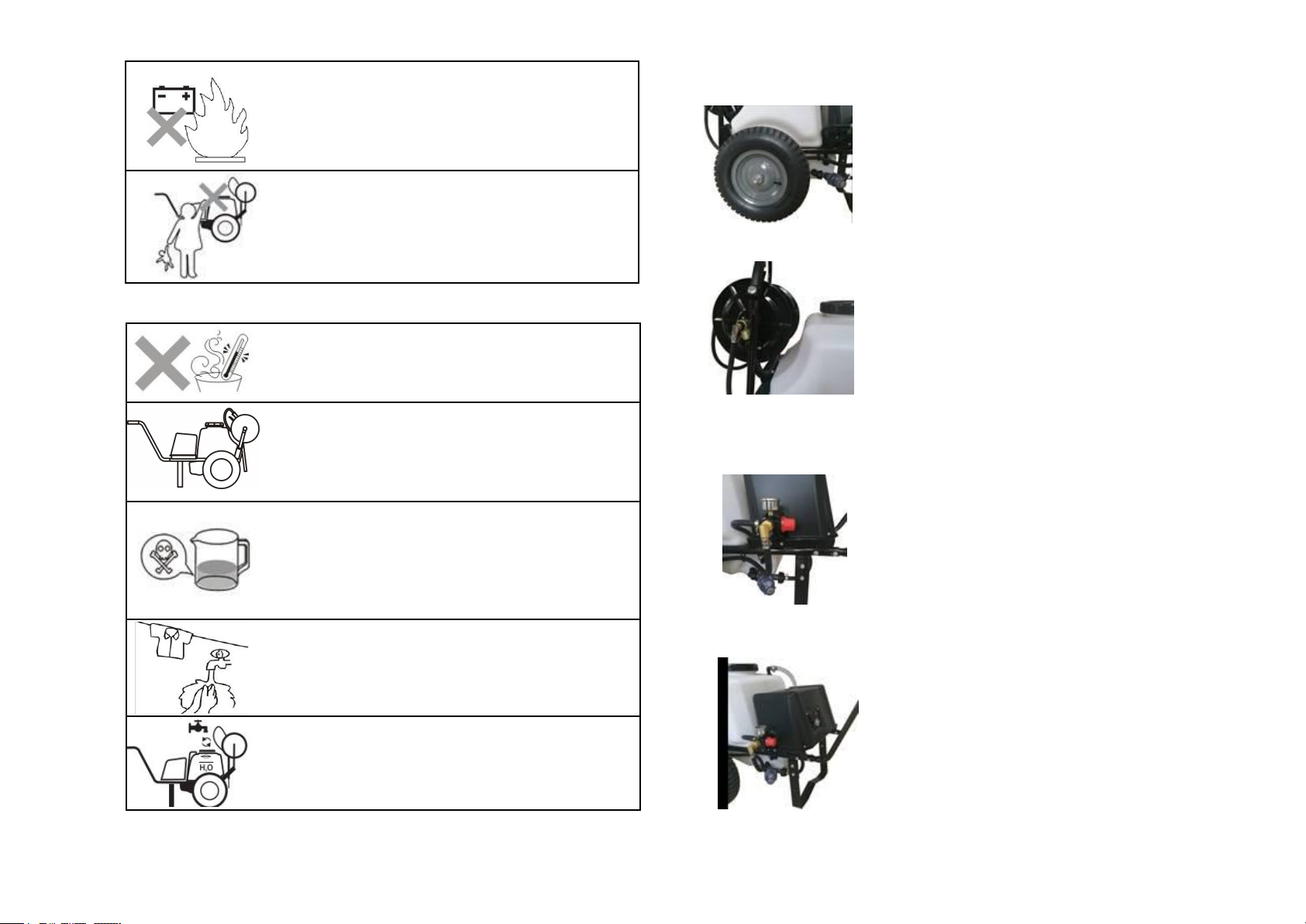
Never put the waste batteries into the fire or
disassemble them without authorization. They
should be collected and handed over to the
manufacturer or environmental protection
authority for recycling.
Don’t keep it at a public place unattended which
may endanger public security.
Notes
The operating temperature of the Sprayer should
not exceed 45°C. Don’t operate when the ambient
temperature is higher than 45°C or lower than -
10°C.
Trial spraying with clean water, a check of various
joints for possible leakage and a check for
atomization condition are required prior to initial
operation. Make sure everything is ok before
preparing the chemical solution.
The preparation of chemical shall follow the
instructions and formula furnished by the pesticide
manufacturer. Unauthorized altering of the dilution
rate of chemical is prohibited, which may either
endanger the human being and animal, or result in
the failure of pest control.
Upon the finish of operation, you shall change
clothes and wash those exposed part of body such
as hands and face. In case of highly toxic pesticide
and germicide, a shower after operation is required
to ensure safety
After use, clean with water and spray the water out
of the spray gun.
V. Installation of the sprayer
1. Installation of Wheel
Insert the axle into the axle tube of the frame,
before mounting the wheel onto the axle, followed
by putting on flat washer 16, spring washer 16,
M16 nut, and M16 cap nut ,and tightening finally.
2.Installation of hose reel
a.Attach the Reel support to the mounting stand w
ith two M8×20 hexagon bolts before fastening wit
h M8 nuts.
b.The three-way sleeves on both sides of the hos
e reel are respectively mounted on the Reel supp
ort, Use two axis pin 6×35 to pass through the thr
ough-holes on the three-way sleeves and the Ree
l support respectively, and then install the Flat wa
sher 6. Use R-pin 1.8×32 bolt shaft hole to lock.
3. Installation of high pressure connecting hose
Pass the high-pressure connecting hose through t
he lifting ring under the frame and connect it to th
e pump head union(in the accessory package),Pu
t washerØ10×Ø19.3×2 in the pump head union, t
hen install it to the outlet of the pressure regulator,
lock pump head union.
4. Installation of Handlebar
Insert the two Handlebars into the corresponding
frame tube (under the electric control box), and fix
them by inserting four M8 ×40 bolts into the
designated holes, followed by fastening with M8
nuts.

5. Fuse tube installation
Take out fuse tube and fuse cap from the instructio
n bag,Insert the fuse tube into the fuse holder,Then
tighten the fuse cap clockwise.
(After installing the fuse tube, the voltmeter pointer
should rotate to the green area of the dial)
VI. Operation of the Sprayer
Charging Before charging, please confirm whether
the charger input parameters are consistent with the
mains supply. If not, please contact the dealer.
The battery of the sprayer has been charged upon
delivery. Due to self-discharge in the process of
transportation and storage, you are suggested to
check the voltmeter before operating. If the indicator
is in yellow or red area, a re-charging is suggested.
When the charge indicator moves to green area, it
indicates the battery has been fully charged.
Note: please use the charger provided by the
manufacturer to charge The Sprayer
Voltmeter The Sprayer is equipped with a
high-precision voltmeter with the voltage indication
range between DC11V~15V. The green area of the
dial indicates that the battery has been fully charged for
normal operation; the yellow area indicates that the
voltage is insufficient but still capable of further
operation; the red area on the left side indicates that
the voltage is seriously insufficient and needs to be
charged immediately. The scale and value above the
color scale indicates the percentage of the battery's
current capacity to that of full charge. If the sprayer has
been used for a short time, it’s not necessary to charge
after every use. If it is put idle for a long time, a regular
(every one or two months) full discharging followed by
full charging is suggested.
Refilling of chemical Prior to each spraying
operation, remove the spray tank cap and fill the tank
with prepared chemical solution through the filter,
followed by replacing and tightening the tank cap
Notes:1. Trial spraying with clean water and checking
various joints for possible leakage are required prior
to initial operation. Make sure everything is ok before
starting spray operation.
2. The sprayer should not be submerged
directly into the water to fetch water or clean.
Power switch Press the red button next to the
charging port and voltmeter to power on/off the
pump.
Note: 1.The sprayer is designed with overload
protection function. While the power switch is
activated, the pump will stop working by itself once
the spray gun shut-off is at OFF position or the
nozzle is blocked. While the spray gun shut-off is
switched to ON position , the pump will start
operation by itself.(The automatic start/stop system
is only applicable when the battery power exceeds
50%)
2. If the Sprayer is put idle for a long time,
the power switch should be turned off in time.
Pressure regulator The working pressure of the
pump may be varied depending on the nozzle and

the object of application, so as to improve the size
of spraying droplets.
The pump pressure may be varied between 0 to
10 bars. Rotate the pressure regulating knob
clockwise to increase; and anticlockwise to
decrease the pressure.
Pressure gauge Display the working pressure of
the pump.
Liquid level line Through the transparent tube
between the electric control box and the spray tank,
the volume of the chemical liquid in the spray tank
can be viewed, and the red floating ball indicates
the liquid level height.
Spray gun shut-off assembly
The handle is equipped with a hook to lock the trigger for continuous
spraying, contributing to convenient operation for the operators.
1. Shut 2. Continuous
Adjustment of nozzle The fogging angle may be varied by rotating the
nozzle. Tightening the nozzle to provide higher
fogging angle, finer fog droplets, and wider
spraying width; loosening to nozzle to obtain
smaller fogging angle, larger flow rate, and
longer spraying distance.
VII. Cleaning and maintenance
After each application, the sprayer should be cleaned to prevent the
corrosion or blocking of the sprayer by pesticides, meanwhile avoid
mixing of chemicals of different varieties between the residual liquid of
this and next applications, which may adversely affect the application
performance or cause harm to crops.
Clean the external surface of the sprayer with a wet cloth. Fill the
tank with clean water and start the pump to spray
until the sprayed water becomes clean. The
remaining water in the spray tank can be
discharged through the water outlet.
Outlet Rotating the drain nut to discharge the
residual liquid or cleaning water. After cleaning,
re-tighten the drain nut.
Cleaning of Filter Rotate anticlockwise to
remove the transparent housing before pulling out
the strainer for a rinsing with water.
Note: When there is chemical in the spray tank,
the chemical may flow out in the process of
removing filter housing.
VIII. Storage
The Sprayer should be stored indoors at a dry place out of reaches of
children. In case of storage for a long time, a regular (every one or two
months) full discharging/charging is required.
When the pest-control season is over and the sprayer is to be stored
for a long time, the sprayer shall be thoroughly cleaned and the residual
water in the pump and pipeline shall be thoroughly removed to prevent
against freezing in winter.
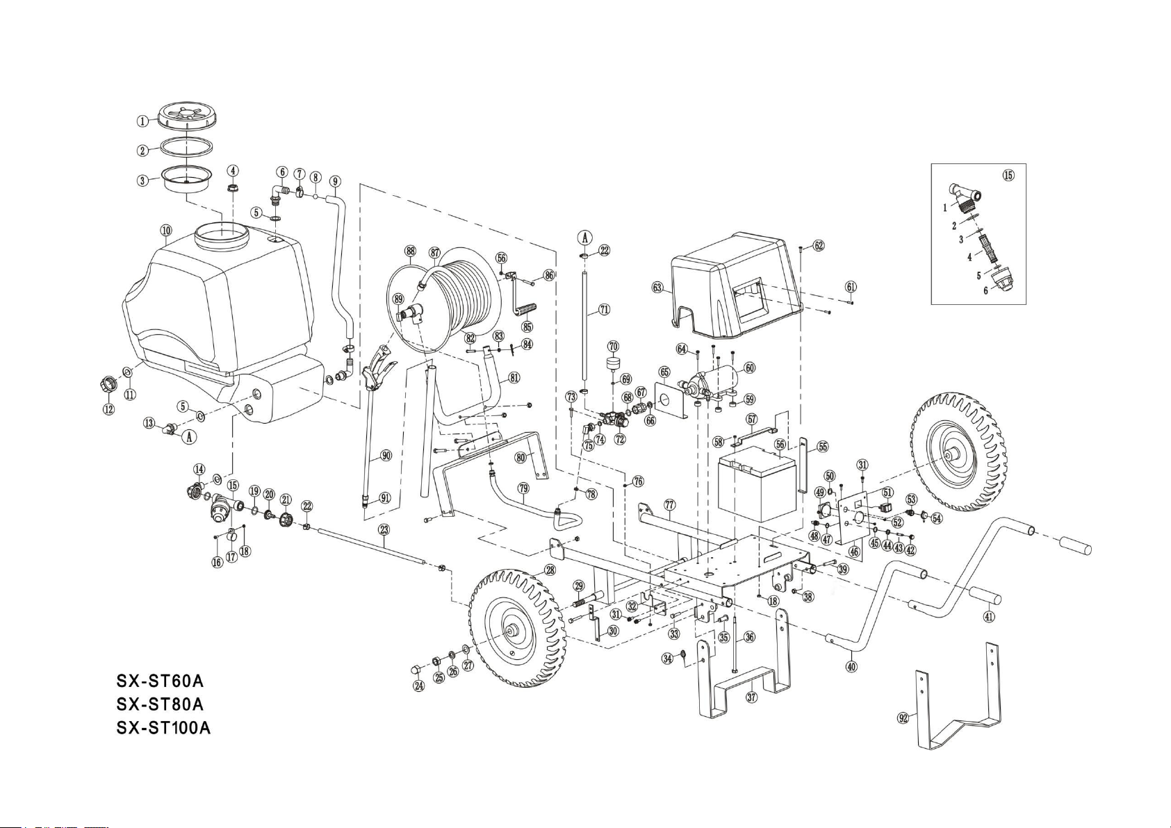
IX. Structural drawings and schedules
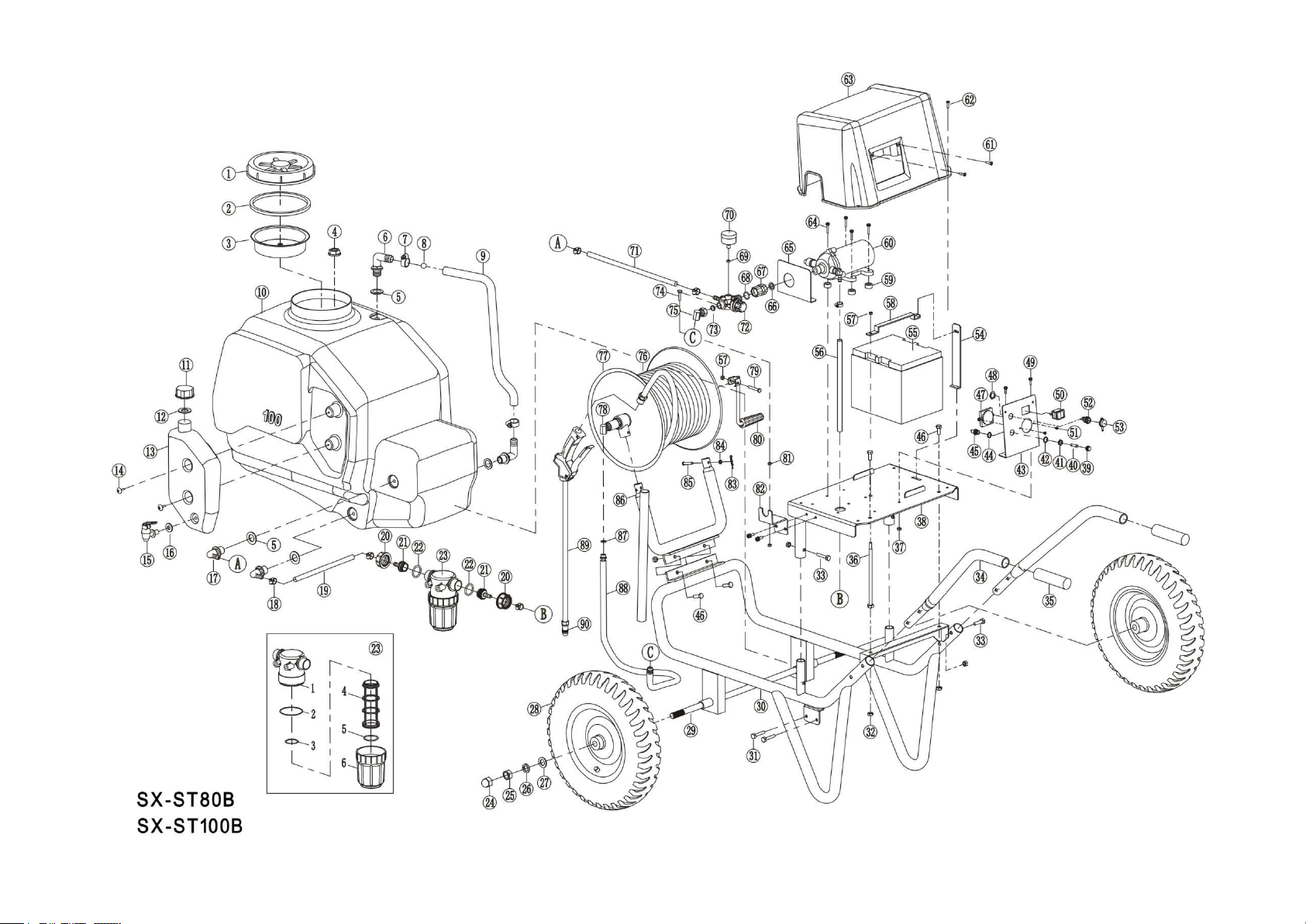

Schedules of SX-ST60A/SX-ST80A/SX-ST100A
Schedules of SX-ST80B / SX-ST100B
SN
Part Description
Qty.
SN
Part Description
Qty.
1
Tank Lid
1
30
Filter rack
1
2
Washer for spray tank port
1
31
Cross groove screw M5 × 16
6
3
strainer
1
32
pressure regulator bracket
1
4
Elbow nut
4
33
Hexagonal Bolt M8×20
6
5
Seal Washer Ø20.3×Ø30×3
4
34
Ring lock pin 4 × 25
2
6
Right angle elbow
2
35
Pin with hole 12 × 40
(for SX-ST80A / 100A)
2
7
Pipe-clip 14-27
2
36
Hexagonal Bolt M6×180
1
8
Floating ball
1
37
foot stand(for SX-ST80A/100A)
1
9
Trans. steel wire hose
1
38
Hexagon lock nut M8
12
10
spray tank
1
39
Hexagonal Bolt M8×40
6
11
Washer for drain cap
1
40
Handlebar
2
12
Drain cap
1
41
Handle cover
2
13
Water-return joint
1
42
Fuse cap
1
14
Water inlet Union
1
43
Fuse tube 15A
1
15
filter
1
44
Fuse holder nut
1
15-1
Filter body
1
45
Flat washer
1
15-2
O Ring Ø41×3.5
1
46
panel
1
15-3
O Ring Ø24.5×3.5
1
47
Plastic gasket
1
15-4
strainer
1
48
Fuse holder
1
15-5
O Ring Ø25.5×3.5
1
49
voltmeter
1
15-6
Transparent housing
1
50
Charging seat nut
1
16
cross head screw M5×12
1
51
power switch 30A
1
17
Stainless steel clamp Ø25
1
52
Self tapping screw w/pad ST2.9×8
2
18
Hexagon lock nut M5
13
53
charging seat
1
19
O Ring Ø27×3
2
54
dust cover
1
20
Filter connector
1
55
Battery holder
1
21
Filter lock cap
1
56
battery
1
22
Pipe-clip 13-19
4
57
retainer plate
1
23
Inlet Pipe
1
58
Hexagon lock nut M6
2
24
Cap nut M16
2
59
Damping pad
4
25
hex nut M16
2
60
Water pump
1
26
Spring washer 16
2
61
Cross groove screw M4 × 12
2
27
Flat washer 16
2
62
Cross groove screw M5 × 20
4
28
wheel
2
63
Electric control box cover
1
29
wheel shaft
1
64
Cross groove screw M5 × 25
4
SN
Part Description
Qty.
SN
Part Description
Qty.
1
Tank Lid
1
17
Water-return joint
2
2
Washer for spray tank port
1
18
Pipe-clip 13-19
6
3
strainer
1
19
Water inlet connection hose
1
4
Elbow nut
4
20
Filter lock cap
2
5
Seal Washer
Ø20.3×Ø30×3
4
21
Filter connector
2
6
Right angle elbow
2
22
O Ring Ø23×2.4
2
7
Pipe-clip 14-27
2
23
filter
1
8
Floating ball
1
23-1
Filter body
1
9
Transparent steel wire hose
1
23-2
O Ring Ø66×2.6
1
10
spray tank
1
23-3
O Ring Ø36×2.3
1
11
Water tank cover
2
23-4
strainer
1
12
Washer for drain cap
2
23-5
O Ring Ø41.5×2.65
1
13
water tank
1
23-6
Transparent housing
1
14
Cross groove screw M5 × 12
2
24
Cap nut M16
2
15
water sprout
1
25
hex nut M16
2
16
sprout gasket
1
26
Spring washer 16
2
SN
Part Description
Qty.
SN
Part Description
Qty.
65
baffle
1
79
High pressure connecting
hose
1
66
Seal ring of pump port
1
80
Fixing bracket
1
67
Outlet connection
1
81
Reel support
1
68
O Ring Ø22×2.65
1
82
axis pin 6×35
2
69
Seal Washer
Ø3.5×Ø8.2×2.5
1
83
Flat washer 6
2
70
pressure gauge
1
84
R-pin 1.8×32
2
71
Return Pipe
1
85
rockarm
1
72
pressure regulator
1
86
Cross groove screw M6 × 40
1
73
Bolt for T-groove M5 × 30
1
87
Hose assembly
1
74
washer Ø10×Ø19.3×2
1
88
Reel
1
75
Pump head union
1
89
Reel union
1
76
hex nut M5
1
90
spray gun
1
77
Frame
1
91
Copper nozzle
1
78
O Ring Ø14.5×2.4
2
92
foot stand (for SX-ST60A)
1

List a
X.Troubleshooting
Problems
Analysis
Solutions
Pump doesn't
work after power
on
·The fuse is blown
·The battery is dead
·The power switch is damaged
·Power wires come off
·Motor damaged
·Replace
·Charging
·Replace the switch
·Remove the cover of the
electric control box and
secure the connection of
the wires.
·Replace the motor
Abnormal noise
heard while the
pump rotates
·The fastening screws of pump
is loose
·Tighten the screws
Pump powers
on-off
intermittently
·The work pressure is too high
·Turn the pressure knob
counterclockwise to lower
the pump pressure or
adjust the copper nozzle
to increase the spray
volume.
water leakages
·Damage or looseness occurs to
pipe joints
·The pump head is loose or the
diaphragm is damaged
·Tighten the locking nuts
Tighten the hose clamp
Replace the gasket and
repair it
·Tighten the screw and
replace the water pump
Poor spray
·Pump pressure is set too low
·Low battery power
·The hose is twisted or folded
·Filter or spray gun clogged
·Nozzle wears
·Pump ages
·Turn the pressure regulator
knob clockwise to
increase the pump
pressure
·Charging
·Repair
·Remove impurities
·Replace the nozzle
·Replace
The pump works
but the spray gun
doesn’t spray
water
·The inlet is completely blocked
·The pressure regulator has
been set to the lowest point
and the liquid returns to the
tank
·Valve conglutinates (usually
occurring upon initial use or
after long-term storage)
·Clean up
·Turn the pressure regulator
knob clockwise to
increase the pump
pressure
·Add a small amount of
clean water into the spray
tank, rotate the pressure
regulator anticlockwise to
the dead point, turn on the
power switch until the
liquid pump sprays water
SN
Part Description
Qty.
SN
Part Description
Qty.
27
Flat washer 16
2
59
Damping pad
4
28
wheel
2
60
Water pump
1
29
wheel shaft
1
61
Cross groove screw M4 × 12
2
30
Frame
1
62
Cross groove screw M5 × 20
4
31
Hexagonal Bolt M8×12
2
63
Electric control box cover
1
32
Hexagon lock nut M8
10
64
Cross groove screw M5 × 25
4
33
Hexagonal Bolt M8×40
8
65
baffle
1
34
Handlebar
2
66
Seal ring of pump port
1
35
Handle cover
2
67
Outlet connection
1
36
Hexagonal Bolt M6×180
1
68
O Ring Ø22×2.65
1
37
Hexagon lock nut M5
14
69
Seal Washer Ø3.5×Ø8.2×2.5
1
38
Pallet assembly
1
70
pressure gauge
1
39
Fuse cap
1
71
Return Pipe
1
40
Fuse tube 15A
1
72
pressure regulator
1
41
Fuse holder nut
1
73
washer Ø10×Ø19.3×2
1
42
Flat washer
1
74
Bolt for T-groove M5 × 30
1
43
panel
1
75
Pump head union
1
44
Plastic gasket
1
76
Hose assembly
1
45
Fuse holder
1
77
Reel
1
46
Hexagonal Bolt M8×20
4
78
Reel union
1
47
voltmeter
1
79
Cross groove screw M6 × 40
1
48
Charging seat nut
1
80
rockarm
1
49
Cross groove screw
M5 × 16
6
81
hex nut M5
1
50
power switch 30A
1
82
pressure regulator bracket
1
51
Self tapping screw with pad
ST2.9 × 8
2
83
R-pin 1.8×32
2
52
charging seat
1
84
Flat washer 6
2
53
dust cover
1
85
axis pin 6×35
2
54
Battery holder
1
86
Reel support
1
55
battery
1
87
O Ring Ø14.5×2.4
2
56
Water inlet hose
1
88
High pressure connecting hose
1
57
Hexagon lock nut M6
2
89
spray gun
1
58
retainer plate
1
90
Copper nozzle
1

and returns to the spray
tank, or spray or blow the
water pump from the
water inlet pipe with
high-pressure water or
small air inflator until the
water pump works
normally
The battery fails
to be re-charged
·Poor contact of charging plug
·Internal wires in the Sprayer
breaks
·The input/output lines of charger
are damaged or broken
·The charger is damaged
·The battery is damaged
·Repair or replace the
charging socket
·Remove the cover of the
electric control box and
connect the wires firmly
·Call a professional
technician to repair
·Replace
·Replace
The green light
keeps on during
charging
·Has fully charged
·Poor contact between socket
and charging plug
·The charger malfunctions
·Open circuit
·Faulty soldering or
disconnection of charging
circuit
·OK
·Repair or replace the socket
·Replace
·Repair
·Repair
The red light
keeps on during
charging
·Under charging
·The charger malfunctions
·Battery ages
·The power switch has not been
turned off
·OK
·Replace·Replace
·Replace·Replace
·Turned off
The indicator
does not light up
when charging
·There is no electricity in the
mains socket
·The charger malfunctions
·Repair
·Replace
XI. Packing list
XII. SX-ST80A /SX-ST100A accessories (purchased separately)
S/N
Descriptions
Unit
Qty.
Remarks
1
Sprayer body
unit
1
2
Handlebar
piece
2
3
wheel axle
piece
1
4
wheel
piece
2
5
Reel and spray gun assembly
set
1
S/N
Descriptions
Unit
Qty.
Remarks
6
Reel support
piece
1
7
Charger
unit
1
8
Fuse tube 15A
piece
2
9
Fuse cap
piece
1
10
Instruction Manual
piece
1
11
Accessory
Package
Hexagonal Bolt M8×40
piece
4
Hexagonal Bolt M8×20
piece
2
Hexagon lock nut M8
piece
6
axis pin 6×35
piece
2
Flat washer 6
piece
2
R-pin 1.8×32
piece
2
Pump head union
piece
1
washer Ø10×Ø19.3×2
piece
1
hex nut M16
piece
2
Spring washer 16
piece
2
Flat washer 16
piece
2
Cap nut M16
piece
2
Pipe-clip 13-19
piece
2
(I)Installation of accessories
1.Installation of traction bracket and
traction rod
Insert the double-rod end of the traction
bracket into the frame tube (under the
electric control box), before leading four
M8 × 40 bolts into the designated holes
and fastening with the M8 nut; followed by
inserting the single-rod into the traction
rod, and fastening with two M8 × 50 bolts
and M8 nuts.
2.Installation of spray boom
Put the folding boom horizontally on the
bracket, and lead two M8 * 40 hex bolts
into the two fixing holes in the bracket and
the spray boom, followed by fastening
with two M8 nuts (the folding direction of
the boom should be towards the rear of
the sprayer).
3.Installation of connecting hose
Lead the connecting hose through the
lifting ring under the frame and connect it
with the pump head. Connect the nut at the
other end of the connecting hose to the tee joint
of the folding boom.
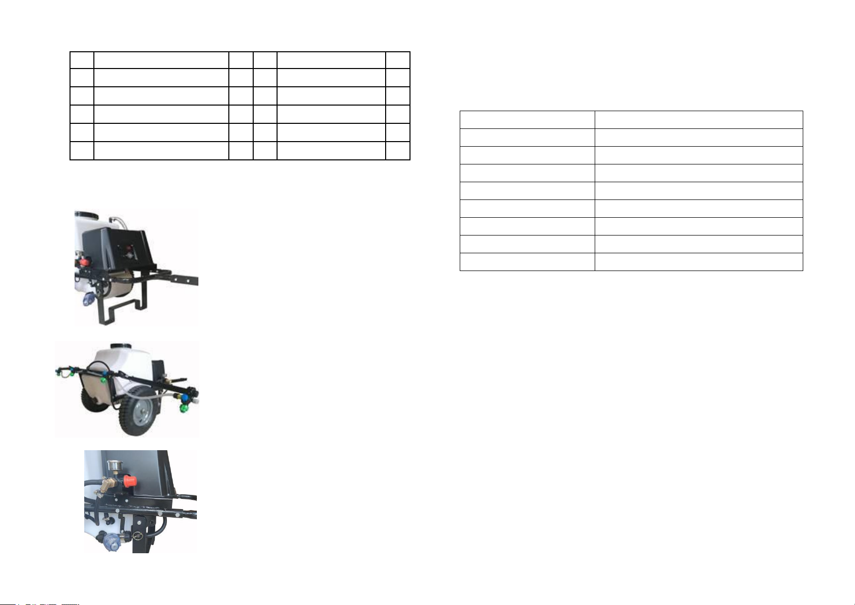
(II) Tech Parameters
Nozzle Model
110-01.5
Nozzle Type
Drip-proof fan nozzle
Nozzle spraying angle
110°
Spraying width
2.5m
Nozzle quantity
6 pcs
Nozzle spacing
500mm
Max. Pressure
7bar
Suggested Pressure
3bar
Single nozzle volume
0.7L/min(3bar)
(III) Adjustment of sprayer and operation
1. Upon the finish of installation of the Sprayer, check nozzles and various
connections to make sure they are sound. Extend the spray boom and
make sure the inclination angle between the nozzle slit and the spray
boom to be 5 ~ 10 degrees, and the spacing between nozzles on the spray
boom to be 0.5m.
2. Prior to operation, a trial spraying with clean water for possible leakage
at various connection points is required. Rotate the pressure regulator to
3bar (Extra-high working pressure may lead to spray drifting and
extra-wearing of nozzle). Turn off the power switch after confirming that the
sprayer is in good condition.
3. The traction rod of the sprayer shall be connected to the tractor with a 12
× 65 pin with split hole, followed by securing with a 4 × 25 cotter ring.
4. Remove the 4 × 25 cotter ring on both sides of stand and pull out 12 × 40
pin with split hole, followed by rotating the stand to the horizontal position,
S/N
Descriptions
Qty.
S/N
Descriptions
Qty.
1
Folding boom assembly
1
6
Ring lock pin 4 × 25
1
2
Traction rod
1
7
Hexagonal Bolt M8×50
2
3
Traction bracket
1
8
Hexagonal Bolt M8×40
4
4
Connecting tube
1
9
Hexagonal Bolt M8×20
2
5
Pin with split pin hole 12 × 65
1
10
Hexagon lock nut M8
8

before inserting the 12 × 40 pin with split hole into the fixing hole which
is secured with the 4 × 25 cotter ring.
5. Fill the sprayer with clean water, and the pesticide of a certain
proportion, followed by stirring and mixing evenly. Turn on the power
switch to start operation .
6. In the process of operation, the speed and direction of spraying shall
be kept constant, free of fluctuation of speed or deviation of route. In
case any blockage, leakage or other fault occurs to the nozzle , power
off the sprayer in time for troubleshooting.
7. Before being moved to another site or put aside for storage, the
spray boom shall be folded and secured. If the nozzle angle affects the
folding of the spray boom, loosen the nozzle locking screw to adjust the
nozzle angle before folding. After arriving at the operation site, the
nozzle shall be reset.
8. A filter screen is available in the nozzle. In case the nozzle is blocked,
the filter screen and nozzle can be washed with clean water after
removing the nozzle cap. Never unblock the nozzle by hard objects or
mouth blowing.
This manual suits for next models
4
Table of contents
Other TOPMAQ Paint Sprayer manuals


Popular Paint Sprayer manuals by other brands


Nordson
Nordson Encore LT quick start guide

paasche
paasche LMS-E6-45 Operating instructions and replacement parts list

Graco
Graco ASM Zip Spray 3400G Repair and parts

Graco
Graco LT Series Instructions - parts

Graco
Graco RTX 1500 Repair and parts

Harbor Freight Tools
Harbor Freight Tools 47274 Assembly and operation instructions