Ergo Fix ELECTRIC HEIGHT ADJUSTABLE TABLE Parts list manual
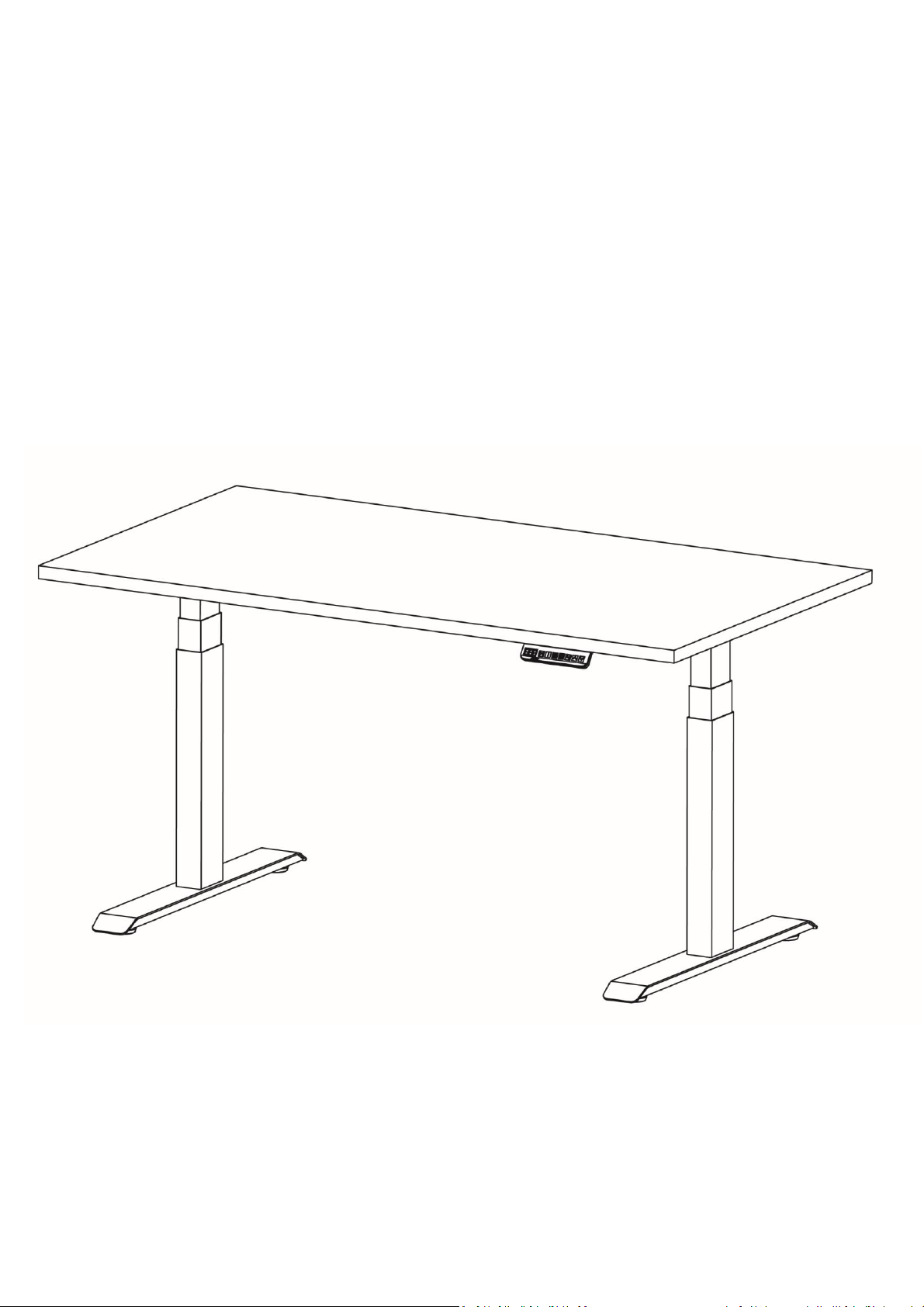
ELECTRIC HEIGHT ADJUSTABLE TABLE
Assembly and Operation Instructions
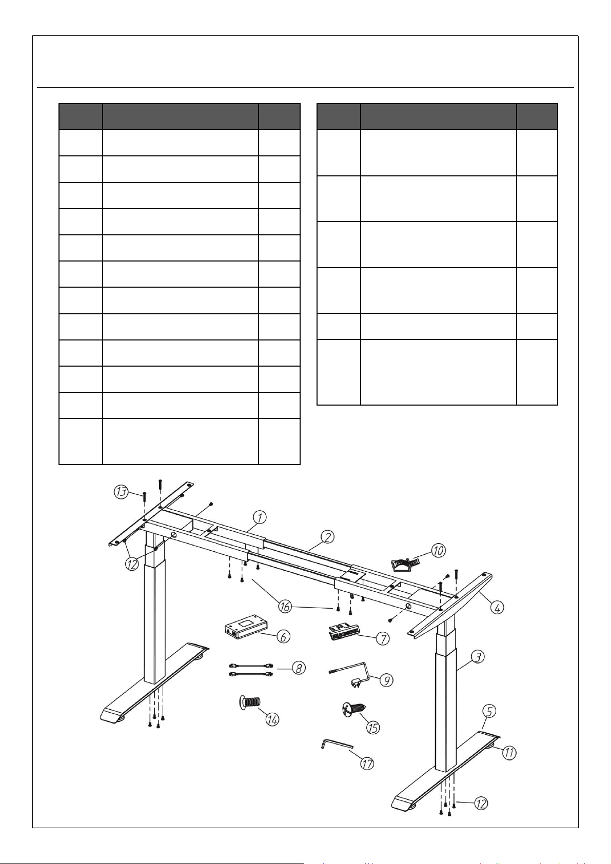
Parts List
Part
Name
Qty
1
End Frame
2
2
Cross Rail
2
3
Lift Column
2
4
Side Bracket
2
5
Foot
2
6
Control Box
1
7
Handset
1
8
Lift Column Cable
2
9
Power Cord
1
10
Cable Clip
8
11
Levelling Foot
4
12
Hex Socket Screws
Pack A
- M6X12mm
16
Part
Name
Qty
13
Hex Socket Screws
Pack B
- M6X35mm
4
14
Hex Socket Screws
Pack C
- M6X14mm
6
15
Wood Screws
Pack D
–M5X16mm
8
16
Hex Socket Screws
Pack E
- M6X10mm
8
17
4mm Allen Key
1
18
Phillips Screwdriver
or Electric Hand Drill
(Not included)
-
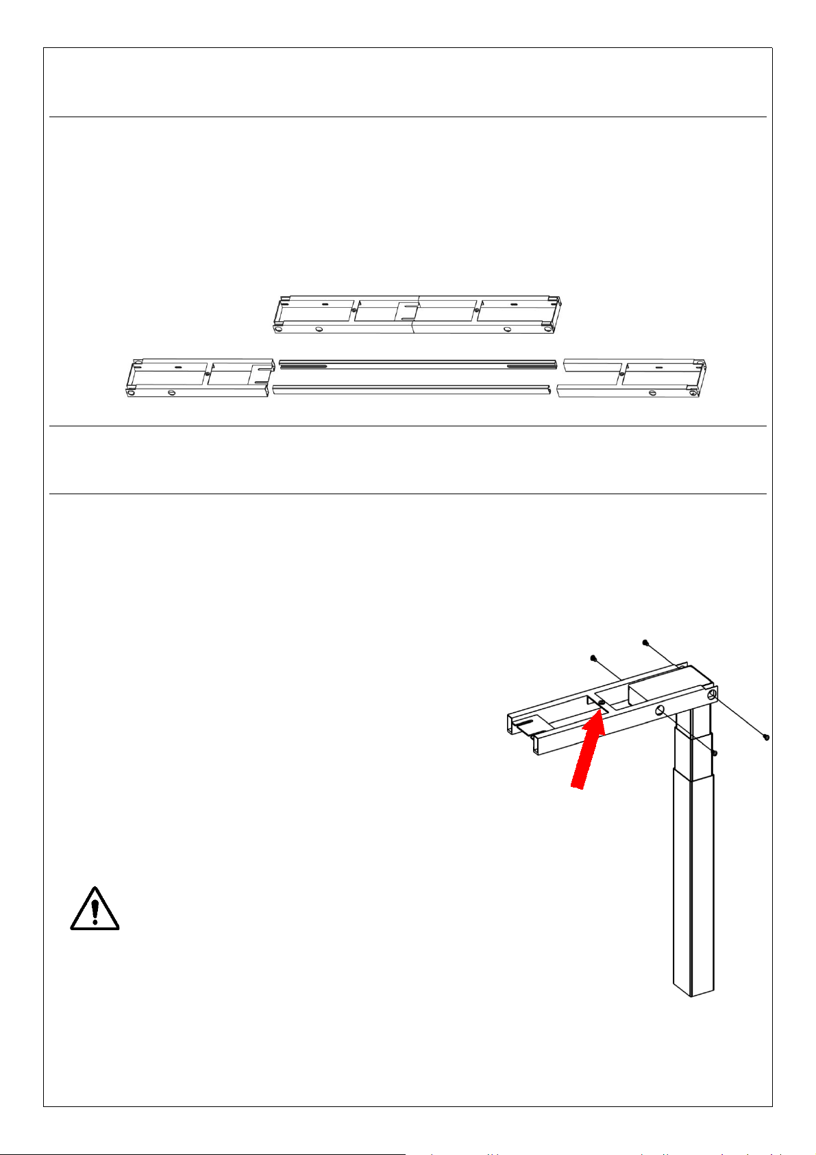
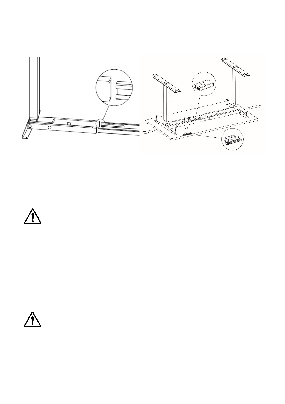
STEP 1
CENTER SCREW HOLE
Lay out all the parts to ensure that all items in the parts list are
present.
Fully separate the End Frames (Part 1). You will find the Cross Rails
(Part 2) inside.
Position Lift Column (Part 3) into the End
Frame (Part 1) as shown in the diagram.
Note: Orientate the center screw hole of
the End Frame flushed to the top surface
of the Lift Column.
Align the edge holes of the Lift Column
with the holes in the End Frame. Insert
and fasten loosely using 4 screws from
Pack A with the supplied 4mm Allen Key
(Part 17).
Do not tighten the screws yet.
Repeat the same process for the other
Lift Column.
STEP 2
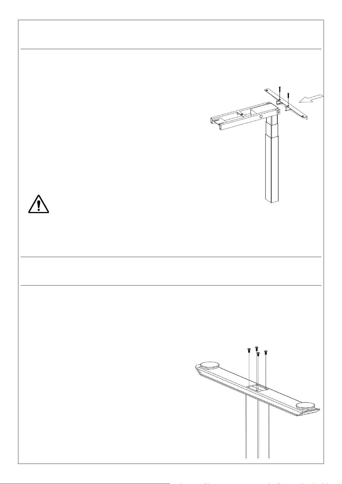
STEP 4
STEP 3
Attach the foot (Part 5) to the bottom of the Lift Column (Part 3) and
align the screw holes. Insert and fasten using 4 screws from Pack A
in a criss-cross pattern.
Repeat the same process for the other Lift Column.
Insert the Side Bracket (Part 4) into the End Frame
(Part 1) and align the screw holes as shown.
Note: You may need to gently tap the bracket
into place to align the screw holes.
Insert and fasten using 2 screws from Pack B.
Repeat the same process for the other Lift
Column.
If there is difficulty fastening the screws,
it may be because some of the earlier
installed screws were fastened too tightly.
Loosen if necessary.
STEP 5
Orientate the side of the table top carton with the text "Face up
during installation" upwards. Open the carton and ensure that the
bottom surface of the table top faces upwards during installation.
Leave the table top in its original carton during installation
to avoid damaging the table top and its work surface.
Place the two assembled Lift Columns (Part 3) on the bottom
surface of the table top and insert the Cross Rails (Part 2) into the
End Frames (Part 1). Ensure the Cross Rail slots face inwards.
Check that the frame assembly is sitting flat on the table top and
tighten the screws in STEP 2 in a criss-cross pattern.
If the frame assembly does not sit flat, loosen screws
installed in step 2. Ensure frame assembly sits flat on the
table top before retightening in a criss-cross pattern.
Option 1: For table tops with AdapTABLE preinstalled nuts:
Align the 6 screw holes (2 on each Side Bracket and 1 on each End
Frame) to the preinstalled nuts on AdapTABLE supplied table tops.
Insert and fasten using 6 screws from Pack C to fix the frame to the
table top.
Option 2: For table tops without preinstalled nuts:
Slide the Lift Columns out and leave approximately 3 –4cm of space
at each end. Center the frame assembly to the table top. Insert and
fasten using 6 wood screws from Pack D to fix the frame to the
table top.
Check and make sure that the supplied wood screws in Pack
D are not too long for the table top. Wood screws which are
too long can puncture and damage the work surface. If the
wood screws are too long, purchase shorter wood
screws which fits your table top.
Maximum width of the frame is 180cm.
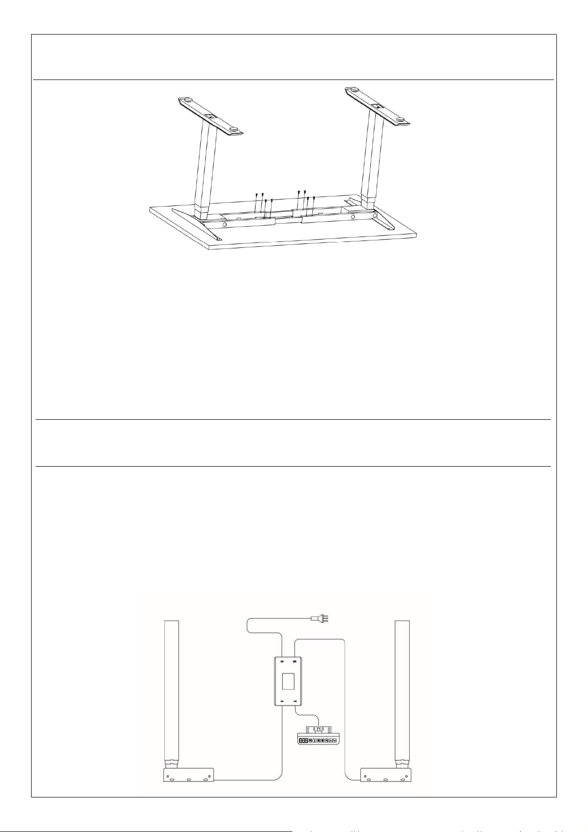
Attach the Control Box (Part 6) by sliding it into the bracket welded
to the End Frame (Part 1).
Align the handset (Part 7) flushed to the front edge of the table top
(tapped holes are available on both sides of AdapTABLE supplied
table tops). Insert and fasten using 2 wood screws from Pack D.
Do not overtighten the screws. Overtightening could cause
damage to the components.
STEP 5 - CONTINUED
STEP 7
Connect the Handset (Part 7) cable to the Control Box (Part 6).
Connect the motor cables on the Lift Columns (Part 3) to the
Control Box using the Lift Column Cables (Part 8). Connect the
Power Cord (Part 9) to the Control Box.
Secure all cables neatly using the Cable Clips provided (Part 10).
Ensure the Cross Rails (Part 2) are positioned evenly within the
End Frames (Part 1). Insert and fasten using 8 screws from Pack E in
a criss-cross pattern to fix the Cross Rails in position.
Note: If the cable cover tray is purchased. Align the cable cover tray
slots to the screw holes before fastening the screws.
STEP 6
THE SET UP IS FINISHED
YOUR ELECTRIC HEIGHT ADJUSTABLE TABLE
IS READY TO BE USED
STEP 8
Turn the assembled table over with minimally 2 personnel by
grabbing the table top (do not grab by the Lift Columns) and using
the feet as pivot points. Adjust the Levelling Feet (Part 11)as
needed.
Plug the Power Cord (Part 9) into the mains and turn on the power.
Reset the frame before use. See Operation Guide for the Reset
Procedure.
Make sure no obstacles are above or below the table.
Make sure the table is not touching any walls.
Make sure all cords have the appropriate length to
accommodate changes in height.

Reset Procedure
To be performed 1) after initial set up and 2) when the system becomes abnormal.
Press and hold the down arrow button until a buzzer sound is heard, signaling
completion of the reset procedure. During the procedure, after the table reaches its
lowest height, the handset displays “RST” while the table shifts slightly down and back
up.It takes approximately 5 seconds after the table reaches its lowest height to complete
the entire reset procedure.
Adjusting Height
Press and hold the up arrow button to move the table up to the desired height, release
to stop. Press and hold the down arrow button to move the table down to the desired
height, release to stop.
Memory Preset
Depending on the handset’s model, it may store up to 3or 4 height presets. Use the
up and down arrow buttons on the handset to reach the desired height. Press the M
button and the handset displays “S-”. Press any of the numeral buttons to preset the
height setting to that corresponding number. Pressing a preset button adjusts the table
automatically to the saved height setting. During automatic height adjustments, pressing
any button stops the adjustment.
Child Lock / Lock
Press and hold the up and down arrow buttons together for approximately 5 seconds.
Child lock is activated when you hear a buzzer sound and the handset flashes “---”.
Release the up and down arrow buttons.
OPERATION GUIDE

Unlock Child Lock / Unlock
When the table has child lock activated, press and hold the up and down arrow
buttons together for approximately 5 seconds. Child lock is deactivated when you hear
a buzzer sound and the handset displays the height value. Release the up and down
arrow buttons.
Sedentary Mode
Press buttons “1”and “3”together and handset displays “0.0h”. Select the sedentary
countdown duration in steps of 30 mins (0.5 = 30 mins) by increasing with the up arrow
and decreasing with the down arrow. The setting will automatically exit by itself after 2
seconds. Upon successful set up of the sedentary mode, the handset’s display flashes
every 5 seconds. When the sedentary countdown ends, users will be notified by buzzer
sounds. Sedentary countdown ranges between 30 mins to 5 hours, in steps of 30 mins.
To cancel sedentary mode: Press buttons “1”and “3”together and handset displays
“X.Xh”(X denotes a numeral). Press the down arrow button till the handset displays
“0.0h”. The setting will automatically exit by itself after 2 seconds.
Set custom maximum and minimum height (good for obstacle avoidance)
Set the maximum height
Move the table to the maximum height you would like to limit the table to. Press the M
and up arrow buttons together for approximately 5 seconds. Release the buttons when
you hear a buzzer sound, signaling maximum height set. To remove the custom
maximum height setting: 1) Use reset procedure or 2) Move the table to the maximum
height followed by pressing the M and up arrow buttons together for approximately 5
seconds. Release the buttons when you hear a buzzer sound, signaling the cancellation
of the custom maximum height.
OPERATION GUIDE

Set the minimum height
Move the table to the minimum height you would like to limit the table to. Press the M
and down arrow buttons together for approximately 5 seconds. Release the buttons
when you hear a buzzer sound, signaling minimum height set. To remove the custom
minimum height setting: 1) Use reset procedure or 2) Move the table to the minimum
height followed by pressing the M and down arrow buttons together for approximately
5 seconds. Release the buttons when you hear a buzzer sound, signaling the
cancellation of the custom minimum height.
Anti-Collision Sensitivity & Unit Of Height Setting
Please kindly contact technical support.
Warning:
Do not move the table continuously for more than 2 minutes without at least an 18
minutes break interval.
To avoid overloading the transformer, there is an overload protection program inbuilt
into the system. If the table stops working, let it cool off for at least 18 minutes before
trying to adjust the height again. “E09”will appear on the handset display if the lifting
mechanisms are overheated.
OPERATION GUIDE

Error Code Key
Code
Meaning
Suggested Actions
E01
Power supply exceed input voltage
range.
Check if power supply is within required input
voltage range.
E02
Lift columns unbalanced by > 10mm.
Perform reset procedure.
E03
Handset not connected.
Plug handset wire connector into the control
box.
E04
Handset communication error.
Check handset for damage. Reconnect handset
wire connector into the control box.
E05
Obstacle detected, anti
-collision
activated.
Release depressed button.
E06
Start up error.
Reconnect all cable connectors into control box.
If problem persists, check with technical
support.
E07
Control system error.
Perform reset procedure.
E08
Table tilts during height adjustment.
Perform reset procedure.
E09
Overheated or duty cycle limit was
reached.
Let the table electronics cool down for at least
18 minutes before using.
E11/21
Motor M1/M2 is not connected.
Plug M1/M2 motor cable connectors into the
control box.
E12/22
Motor M1/M2 current sampling error.
Reconnect M1/M2 motor cable connectors into
control box. If problem persists, check with
technical support.
E13/23
Phase loss or phase line disconnected
from motor M1/M2.
Reconnect M1/M2 motor cable connectors into
control box. If problem persists, check with
technical support.
E14/24
Hall sensor error or hall sensor wire
disconnected
from motor M1/M2.
Reconnect M1/M2 motor cable connectors into
control box. If problem persists, check with
technical support.
E15/25
Motor M1/M2 internal circuit error.
Reconnect M1/M2 motor cable connectors into
control box. If problem persists, check with
technical support.
E16/26
Motor M1/M2 stalled.
Perform reset procedure.
E17/27
Motor M1/M2 directional error.
Reconnect M1/M2 motor cable connectors into
control box. If problem persists, check with
technical support.
E18/28
Table overloaded.
Reduce weight on the table.
OPERATION GUIDE

TECHNICAL SPECIFICATIONS
Height Range
60
–125cm (without desktop)
Base width
110
–180cm
Travel Speed
38mm/s (no load)
Weight capacity
120kg
Motor count
2
Segments
3
Duty Cycle
10
%; Max 2 mins on, Min 18 mins off
Input Voltage
100 VAC
–240 VAC
Noise
<50 dB
Certificates
CE / UL / SAA
Features
Electric motor lifting mechanism
Soft start/stop
Adjustable levelling foot
3
-4 Memory presets (handset dependent)
Metric/imperial units
Child lock function
Sedentary countdown timer
Adjustable anti
-collision system
Custom max and min height set up
Short circuit protection
Overheat protection
Error Code Key
Code
Meaning
Suggested Actions
E40
Series connection error.
Reconnect all cable connectors into control box. If
problem persists, check with technical support.
E41
Series signal error.
Reconnect all cable connectors into control box. If
problem persists, check with technical support.
E42
Memory error.
Reconnect all cable connectors into control box. If
problem persists, check with technical support.
E43
Gyro
-sensor error.
Reconnect all cable connectors into control box. If
problem persists, check with technical support.
OPERATION GUIDE

CAUTION
This sit stand table has electric motors and is designed for use in dry work areas only.
The table height is adjustable so that it can be positioned at the most ergonomically
suitable height. Any other use is at user’s risk. Under no circumstances does the
manufacturer accept warranty claims or liability claims for damages caused from
improper use or handling of the table frame.
Make sure no obstacles are above or below
the table. Make sure the table is not touching
any walls. Make sure all cords have the
appropriate length to accommodate changes
in height.
WARNING! PINCHPOINT!
USE & LIABILITY


