ERISSON H2163 User manual

FILE NO. SM-CTV-G-036
COLOR TELEVISION
SERVICE MANUAL
MODEL NO.
H2163,PF2163,H2165,PF2165
CHASSIS NO. CH-16CA
Please read this manual carefully before service.
1

SERVICE MANUAL
TABLE OF CONTENTS
SAFETY INSTRUCTIONS AND MAINTENANCE .....................................1
X-Ray Radiation Precaution...............................................................................................1
Safety Precaution ................................................................................................................1
Product Safety Notice .........................................................................................................2
Maintenance.......................................................................................................... 3
KEY ICS AND ASSEMBLIES..................................................................................4
SYSTEM BLOCK DIAGRAMS...............................................................................5
Structure Block Diagram.....................................................................................................5
Block Diagram for Supply Voltage System .....................................................................6
SERVICE DATA................................................................................................................7
Technical Data of Key ICs ..................................................................................................7
Service Data of Key ICs .....................................................................................................18
Waveforms of Key Points...................................................................................................23
ADJUSTMENTS..............................................................................................................29
Set-up Adjustments..............................................................................................................29
Circuit Adjustments..............................................................................................................31
Service Mode and Bus Data..............................................................................................33
APPENDIX
Circuit Diagrams
Exploded View
2

SERVICE MANUAL
SAFETY INSTRUCTIONS AND MAINTENANCE
WARNING: BEFORE SERVICING THIS CHASSIS, READ THE
“
X-RAY RADIATION
PRECAUTION
”
,
“
SAFETY PRECAUTION
”
AND
“
PRODUCT SAFETY NOTICE
”
INSTRUCTIONS BELOW.
X-RAY RADIATION PRECAUTION
1. The EHT must be checked every time the TV is serviced to ensure that the CRT does not emit
X-ray radiation as result of excessive EHT voltage. The maximum EHT voltage permissible in
any operating circumstances must not exceed the rated value. When checking the EHT, use
the High Voltage Check procedure in this manual using an accurate EHT voltmeter.
2. The only source of X-RAY radiation in this TV is the CRT. The TV minimizes X-RAY radiation,
which ensures safety during normal operation. To prevent X-ray radiation, the replacement
CRT must be identical to the original fitted as specified in the parts list.
3. Some components used in this TV have safety related characteristics preventing the CRT
from emitting X-ray radiation. For continued safety, replacement component should be made
after referring the PRODUCT SAFETY NOTICE below.
4. Service and adjustment of the TV may result in changes in the nominal EHT voltage of the
CRT anode. So ensure that the maximum EHT voltage does not exceed the rated value after
service and adjustment.
SAFETY PRECAUTION
WARNING: REFER SERVICING TO QUALIFIED SERVICE PERSONNEL ONLY.
1. The TV has a nominal working EHT voltage. Extreme caution should be exercised when
working on the TV with the back removed.
1.1 Do not attempt to service this TV if you are not conversant with the precautions and
procedures for working on high voltage equipment.
1.2 When handling or working on the CRT, always discharge the anode to the TV chassis before
removing the anode cap in case of electric shock.
1.3 The CRT, if broken, will violently expel glass fragments. Use shatterproof goggles and take
extreme care while handling.
1.4 Do not hold the CRT by the neck as this is a very dangerous practice.
2. It is essential that to maintain the safety of the customer all power cord forms be replaced
exactly as supplied from factory.
3. Voltage exists between the hot and cold ground when the TV is in operation. Install a suitable
isolating transformer of beyond rated overall power when servicing or connecting any test
equipment for the sake of safety.
1

SERVICE MANUAL
4. When replacing ICs, use specific tools or a static-proof electric iron with small power (below
35W).
5. Do not use a magnetized screwdriver when tightening or loosing the deflection yoke assembly
to avoid electronic gun magnetized and decrement in convergence of the CRT.
6. When remounting the TV chassis, ensure that all guard devices, such as nonmetal control
buttons, switch, insulating sleeve, shielding cover, isolating resistors and capacitors, are
installed on the original place.
7. Replace blown fuses within the TV with the fuse specified in the parts list.
8. When replacing wires or components to terminals or tags, wind the leads around the terminal
before soldering. When replacing safety components identified by the international hazard
symbols on the circuit diagram and parts list, it must be the company-approved type and must
be mounted as the original.
9. Keep wires away from high temperature components.
PRODUCT SAFETY NOTICE
CAUTION: FOR YOUR PROTECTION, THE FOLLOWING PRODUCT SAFETY NOTICE
SHOULD BE READ CAREFULLY BEFORE OPERATING AND SERVICING THIS TV SET.
1. Do not slap or beat the cabinet or CRT, since this may result in fire or explosion.
2. Never allow the TV sharing a plug or socket with other large-power equipment. Doing so may
result in too large load, thus causing fire.
3. Do not allow anything to rest on or roll over the power cord. Protect the power cord from being
walked on, modified, cut or pinched, particularly at plugs.
4. Do not place any objects, especially heavy objects and lightings, on top of the TV set. Do not
install the TV near any heat sources such as radiators, heat registers, stove, or other
apparatus that produce heat.
5. Service personnel should observe the SAFETY INSTRUCTIONS in this manual during use
and servicing of this TV set. Otherwise, the resulted damage is not protected by the
manufacturer.
6. Many electrical and mechanical components in this chassis have special safety-related
characteristics. These characteristics are often passed unnoticed by a visual inspection and
the X-ray radiation protection afforded by them cannot necessarily be obtained by using
replacements rated at higher voltages or wattage, etc. Components which have these special
safety characteristics in this manual and its supplements are identified by the international
hazard symbols on the circuit diagram and parts list. Before replacing any of these
components read the parts list in this manual carefully. Substitute replacement components
which do not have the same safety characteristics as specified in the parts list may create
X-ray radiation.
2

SERVICE MANUAL
Safety Symbol Description
The lightning symbol in the triangle tells you that the voltage inside this product may
be strong enough to cause an electric shock. Extreme caution should be exercised
when working on the TV with the back removed.
This is an international hazard symbol, telling you that the components identified by
the symbol have special safety-related characteristics.
FDA This symbol tells you that the critical components identified by the FDA marking have
special safety-related characteristics.
UL This symbol tells you that the critical components identified by the UL marking have
special safety-related characteristics.
MAINTENANCE
1. Place the TV set on a stable stand or base that is of adequate size and strength to prevent it
from being accidentally tipped over, pushed off or pulled off. Do not place the set near or over
a radiator or heat register, or where it is exposed to direct sunlight.
2. Do not install the TV set in a place exposed to rain, water, excessive dust, mechanical
vibrations or impacts.
3. Allow enough space (at least 10cm) between the TV and wall or enclosures for proper
ventilation.
4. Slots and openings in the cabinet should never be blocked by clothes or other objects.
5. Please power off the TV set and disconnect it from the wall immediately if any abnormal
condition are met, such as bad smell, belching smoke, sparkling, abnormal sound or no
picture/sound/raster. Hold the plug firmly when disconnecting the power cord.
6. Unplug the TV set from the wall outlet before cleaning or polishing it. Use a dry soft cloth for
cleaning the exterior of the TV set or CRT screen. Do not use liquid cleaners or aerosol
cleaners.
3

SERVICE MANUAL
KEY ICS AND ASSEMBLIES
Table 1 Key ICs and Assemblies
Serial
No.
Position Model No. Function Description
1 N105
OM8370PS/N3/A
(CH05T1629)
UOC
2 N101 AT24C16 EEPROM
3 N106 TDA9859 Audio processor
4 N401 TDA8356 Vertical output circuit
5 N807 TDA8944J Sound power amplifier
6 A100 TDQ-6F2-M Tuner
7 N802 STR-G5653 Power supply circuit
4
SERVICE MANUAL
SYSTEM BLOCK DIAGRAMS
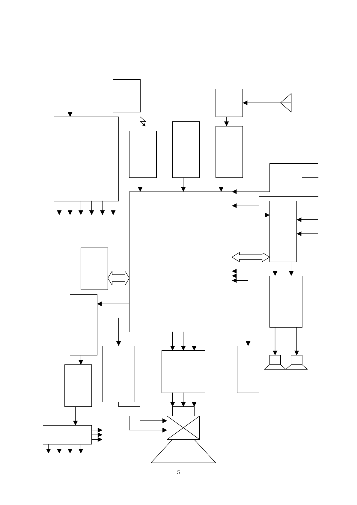
Structure Block Diagram
2 IN 1IC
Small Signal Processor & MCU
UOC
OM8370PS/N3/A (N105)
Audio Processor
TDA9859
(
N106
)
I2C
BUS Y Pb Pr
Audio Amplifier
TDA8944J(N807)
Monitor Out
CRT Drive
IF Pre-Amplifier
+ SAWF
Circuit for Buttons
On The TV
Remote Sensor
HS0038
Remote
control
V
YC L R
V.OUT
TDA8356 (N401)
H.OUT
V502
H.Drive
V501, FL501
EEPROM
(
N101
)
110-220V
50/60Hz
Power Supply Circuit
STR-G5653 (N802) and
BCK-24017L (T803)
FBT
T501
8V
12V
115V
12V-S
5V-1
3.3V
I2C BUS
HV FV SV
200V
45V
16V
5V-2
Fig.1 Structure Block Diagram for CH-16CA Chassis
Tuner
A100
TV-S
SERVICE MANUAL
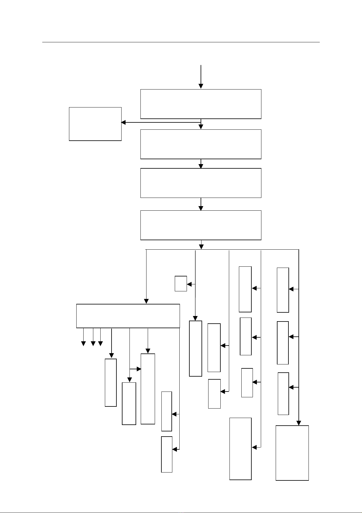
Block Diagram for Supply Voltage System
Fig. 2 Block Diagram for Supply Voltage System for CH-16CA Chassis
6
110-220V
50/60Hz
8V
HV
FV
SV
115V
OM8370 (N105)
V107, V221, V213,
V305,V805, V808,
QB02, QB04, QB05
CRT RGB PCB
TDA9859 (N106)
3.3V
V651
EEPROM REM PCB EHT Limiter Formed of
Q506, etc.
5V-1
Key PCB
OM8370 (N105)
200V CRT RGB PCB
FBT
T501
Power
Regulatio
n and
control
STR-
G5623
(N802)
Interferen
ce proof
Circuit
Formed of
FU001,
T801,
T802,
C801,
C802
Bridge
Rectifier
Formed of
D802~D8
05, and
C803~C8
06
Degaussing
Circuit
Formed of
TH801 and
CN802
Switch
Transform
er BCK-
24013L
(T803)
5V-2
Tuner A100
12V-S
V652
TDA8944J (N807)
COMB PCB
16V
Tuner A100
Vertical Out Circuit

SERVICE MANUAL
SERVICE DATA
Technical Data of Key ICs
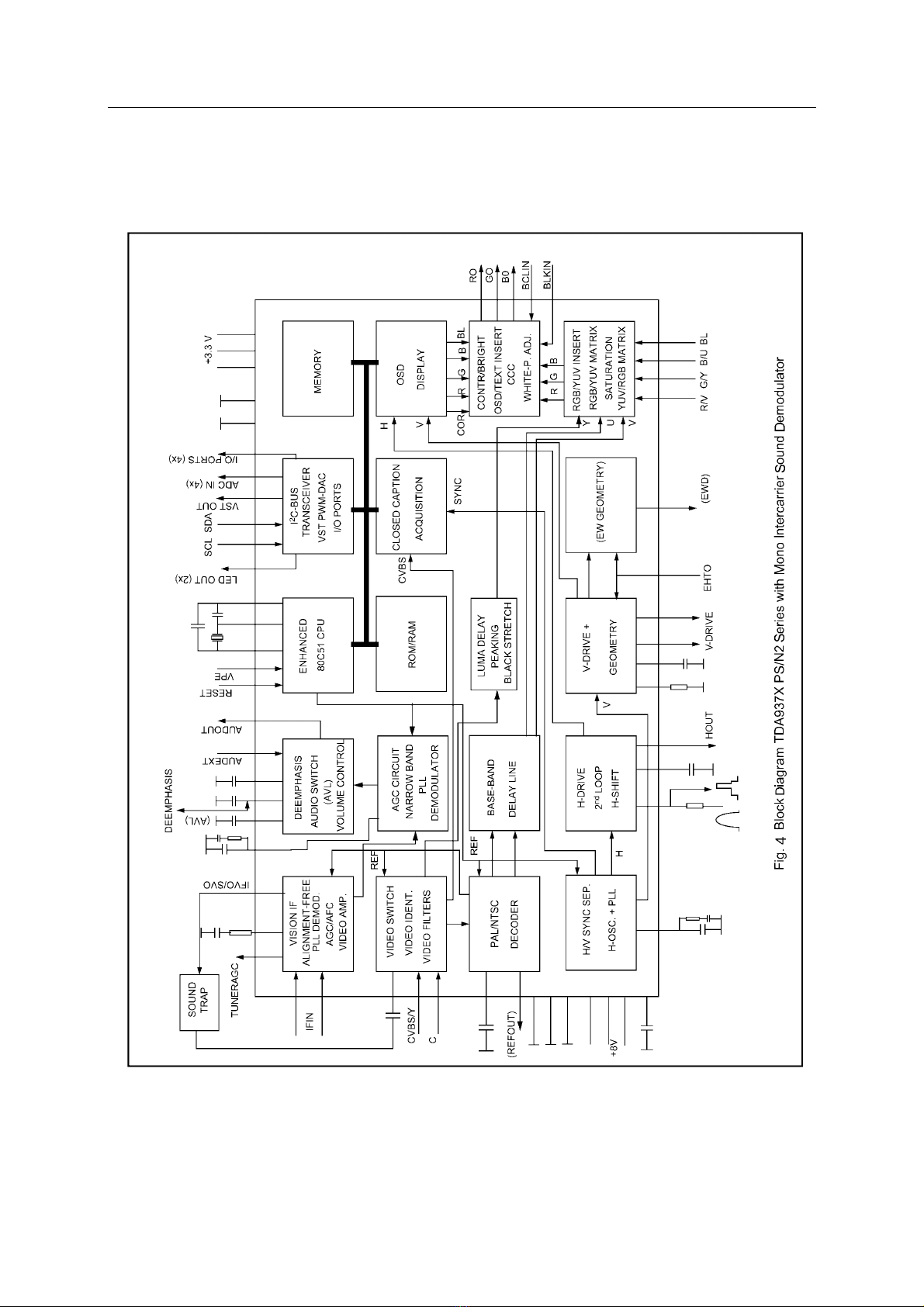
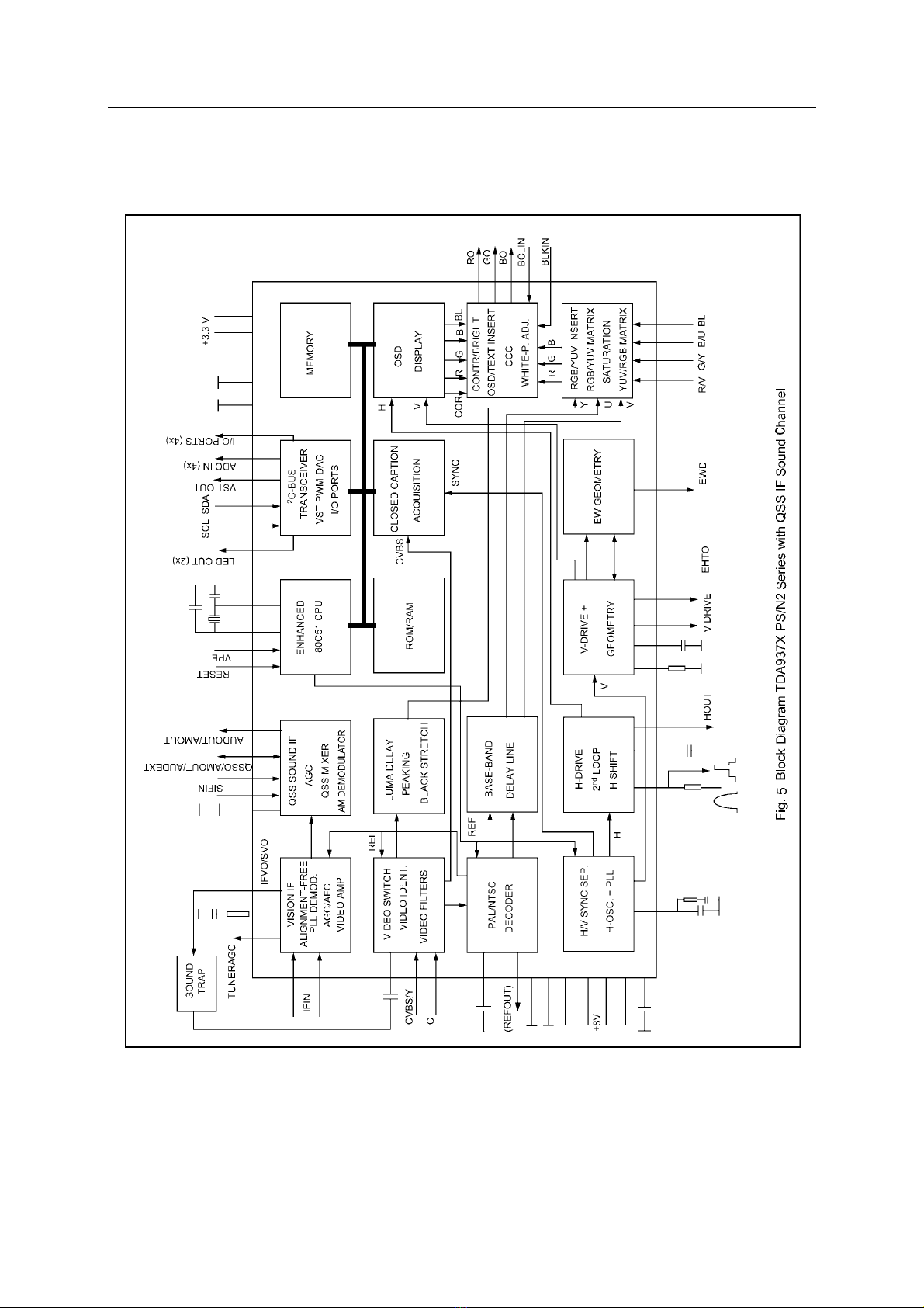
UOC OM837X (N105)
1. General Description
The various versions of the OM837X PS/N3
series combine the functions of a video
processor together with a μ-Controller and
US Closed Caption decoder. The ICs are
intended to be used in economy television
receivers with 90° and 110° picture tubes.
The ICs have supply voltages of 8 V and 3.3V
and they are mounted in an S-DIP 64
envelope.
The features are given in the following feature
list.
2. Features
TV-signal processor
• Multi-standard vision IF circuit with
alignment-free PLL demodulator
• Internal (switchable) time-constant for the
IF-AGC circuit
• A choice can be made between versions with
mono intercarrier sound FM demodulator and
versions with QSS IF amplifier.
• The mono intercarrier sound versions have a
selective FM-PLL demodulator which can be
switched to the different FM sound
frequencies (4.5/5.5/6.0/6.5 MHz).
The quality of this system is such that the
external band-pass filters can be omitted.
• Source selection between ‘internal’ CVBS and
external CVBS or Y/C signals
• Integrated chrominance trap circuit
• Integrated luminance delay line with
adjustable delay time
• Picture improvement features with peaking
(with variable positive/negative overshoot
ratio), black stretching and Dynamic Skin
Tone Control
• Integrated chroma band-pass filter with
switchable centre frequency
• Only one reference (12 MHz) crystal
required for the μ-Controller, Teletext and
the colour decoder
• PAL/NTSC colour decoder with automatic
search system
• Internal base-band delay line
• RGB control circuit with ‘Continuous Cathode
Calibration’, white point and black level offset
adjustment so that the color temperature of
the dark and the light parts of the screen can
be chosen independently.
• Linear RGB or YUV input with fast blanking
for external RGB/YUV sources. The
Text/OSD signals are internally supplied from
theμ-Controller/Teletext decoder
• Contrast reduction possibility during
mixed-mode of OSD and Text signals
• Horizontal synchronization with two control
loops and alignment-free horizontal oscillator
• Vertical count-down circuit
• Vertical driver optimized for DC-coupled
vertical output stages
• Horizontal and vertical geometry processing
• Horizontal and vertical zoom function for 16 :
9 applications
• Horizontal parallelogram and bow correction
for large screen picture tubes
• Low-power start-up of the horizontal drive
circuit
7

SERVICE MANUAL
4. Block Diagrams
9
SERVICE MANUAL
5. Refer to Table 2 about Functions and Service Data of the IC’s Pins.
10

SERVICE MANUAL
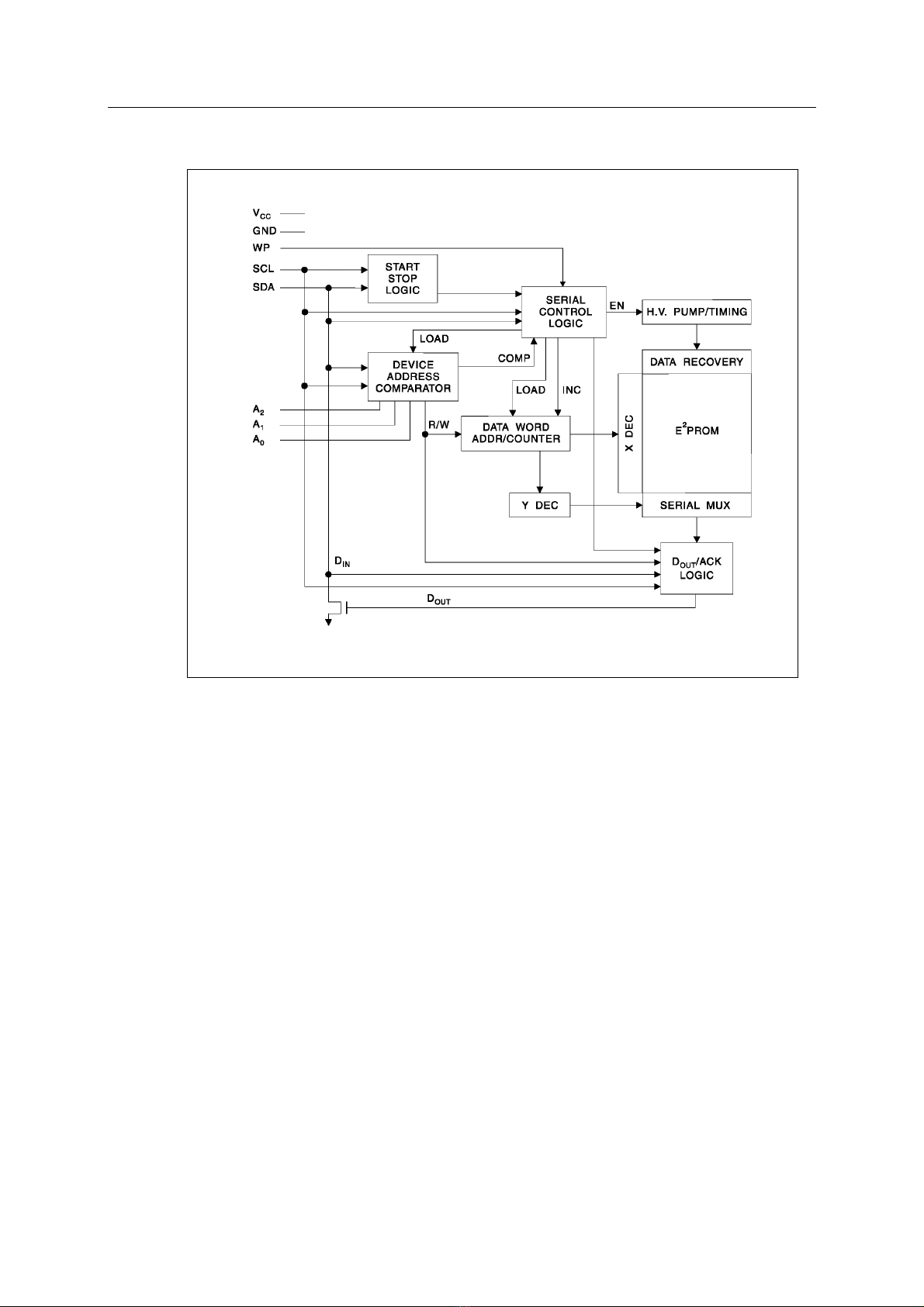
EEPROM AT24C16 (N101)
1. Features
·Low Voltage and Standard Voltage Operation
5.0 (VCC = 4.5V to 5.5V)
2.7 (VCC = 2.7V to 5.5V)
2.5 (VCC = 2.5V to 5.5V)
1.8 (VCC = 1.8V to 5.5V)
·Internally Organized 128 x 8 (1K), 256 x 8 (2K),
512 x 8 (4K),1024 x 8 (8K) or 2048 x 8 (16K)
·2-Wire Serial Interface
·Bidirectional Data Transfer Protocol
·100 kHz (1.8V, 2.5V, 2.7V) and 400 kHz (5V)
Compatibility
·Write Protect Pin for Hardware Data Protection
·8-Byte Page (1K, 2K), 16-Byte Page (4K, 8K,
16K) Write Modes
·Partial Page Writes Are Allowed
·Self-Timed Write Cycle (10 ms max)
·High Reliability
Endurance: 1 Million Cycles
Data Retention: 100 Years
·Automotive Grade and Extended Temperature
Devices Available
·8-Pin and 14-Pin JEDEC SOIC and 8-Pin PDIP
Packages
2. Description
The AT24C01A/02/04/08/16 provides
1024/2048/4096/8192/16384 bits of serial
electrically erasable and programmable read
only memory (EEPROM) organized as
128/256/512/1024/2048 words of 8 bits each.
The device is optimized for use in many
industrial and commercial applications where low
power and low voltage operation are essential.
The AT24C01A/02/04/08/16 is available in space
saving 8-pin PDIP, 8-pin and 14-pin SOIC
packages and is accessed via a 2-wire serial
interface. In addition, the entire family is
available in 5.0V (4.5V to 5.5V), 2.7V (2.7V to
5.5V), 2.5V (2.5V to 5.5V) and 1.8V (1.8V to
5.5V) versions.
Pin Configurations
11
SERVICE MANUAL
3. Block Diagram
Fig. 6
4. Refer to Table 3 about Functions and Data of the IC’s Pins.
12

SERVICE MANUAL
Universal Hi-Fi Audio Processor for TV
TDA9859 (N106)
1. Features
·Multi-source selector switches six AF inputs
(three stereo sources or six mono sources)
·Each of the input signals can be switched to
each of the outputs (crossbar switch)
·Outputs for loudspeaker channel and peri-TV
connector (SCART)
·Switchable spatial stereo and pseudo stereo
effects
·Audio surround decoder can be added
externally
·Two general purpose logic output ports
·I2C-bus control of all functions.
2. General Description
The TDA9859 provides control facilities for
the main and the SCART channel of a TV
set. Due to extended switching possibilities,
signals from three stereo sources can be
handled.
3. Block Diagram
Fig. 7
Note: For extended bass control, the capacitor between CBR/L1 and CBR/L2 should
be replaced by the extended bass control network.
Fig. 18 Block Diagram and Application Circuit.
13
SERVICE MANUAL
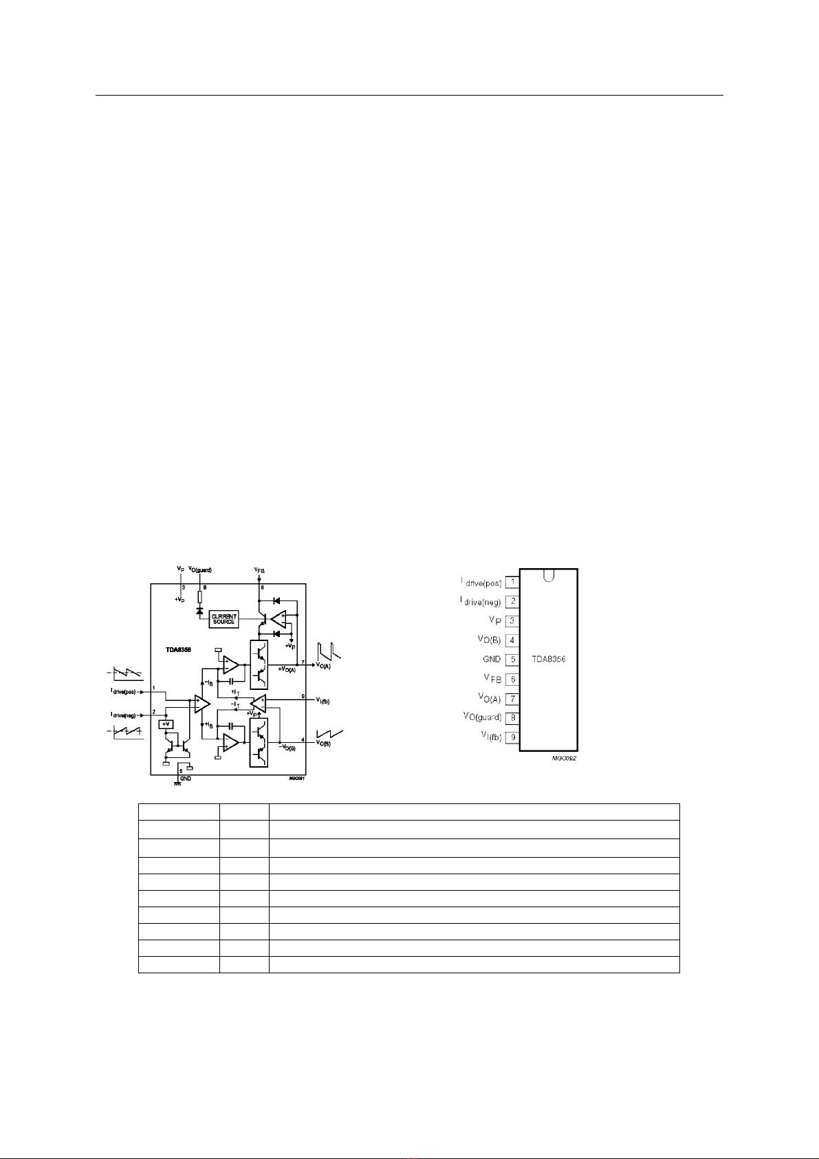
Vertical Scan Output Stage Circuit
TDA8356/N6 (N401)
1. Features
·Few external components
·Highly efficient fully DC-coupled vertical output bridgecircuit
·Vertical flyback switch
·Guard circuit
·Protection against:
Short-circuit of the output pins (7 and 4)
Short-circuit of the output pins to VP .
·Temperature protection
·High EMC immunity because of common mode inputs
·A guard signal in zoom mode.
2. General Description
The TDA8356 is a power circuit for use in 90° and 110° colour deflection systems for field
frequencies of 50 to 120 Hz. The circuit provides a DC driven vertical deflection output circuit,
operating as a highly efficient class G system.
3. Block Diagram Pinning
Fig. 9
Fig. 8
SYMBOL PIN DESCRIPTION
Idrive(pos) 1 Input power-stage (positive);includes II(sb) signal bias
Idrive(neg) 2 Input power-stage (negative);includes II(sb) signal bias
VP 3 Operating supply voltage
VO(B) 4 Output voltage B
GND 5 Ground
VFB 6 Input flyback supply voltage
VO(A) 7 Output voltage A
VO(guard) 8 Guard output voltage
VI(fb) 9 Input feedback voltage
4. Refer to Table 5 about Functions and Data of the IC’s Pins.
14
SERVICE MANUAL
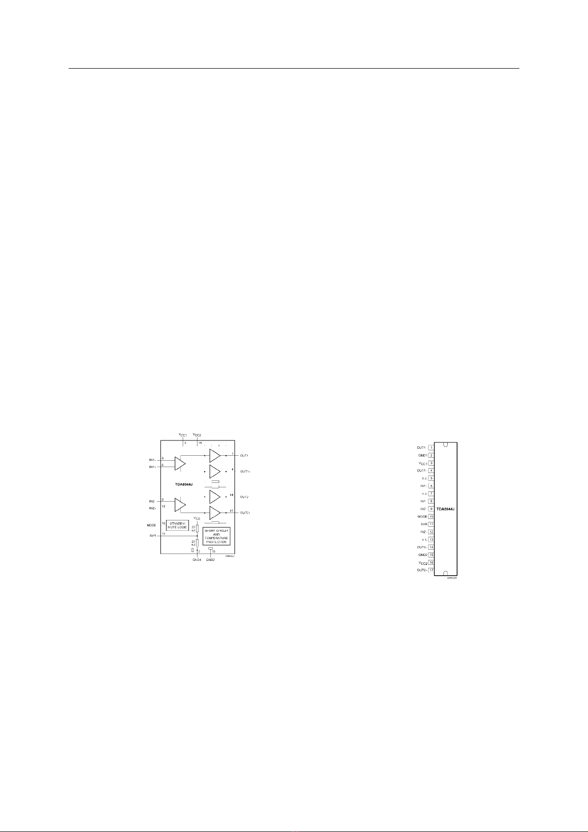
Sound Power Amplifier
TDA8944J (N807)
1.General Description
The TDA8944J is a dual-channel audio power amplifier with an output power of
2 × 7 W at an 8Ω load and a 12V supply. The circuit contains two Bridge Tied Load
(BTL) amplifiers with an all-NPN output stage and standby/mute logic. The TDA8944J
comes in a 17-pin DIL-bent-SIL (DBS) power package. The TDA8944J is
printed-circuit board (PCB) compatible with all other types in the TDA894x family.
One PCB footprint accommodates both the mono and the stereo products.
2. Features
·Few external components
·Fixed gain
·Standby and mute mode
·No on/off switching plops
·Low standby current
·High supply voltage ripple rejection
·Outputs short-circuit protected to ground, supply and across the load
·Thermally protected
·Printed-circuit board compatible.
3. Block Diagram
Pinning
Fig. 10 Block Diagram
Fig. 11 Pin Configuration.
4. Refer to Table 6 about functions and Service Data of the IC’s Pin’s
15

SERVICE MANUAL
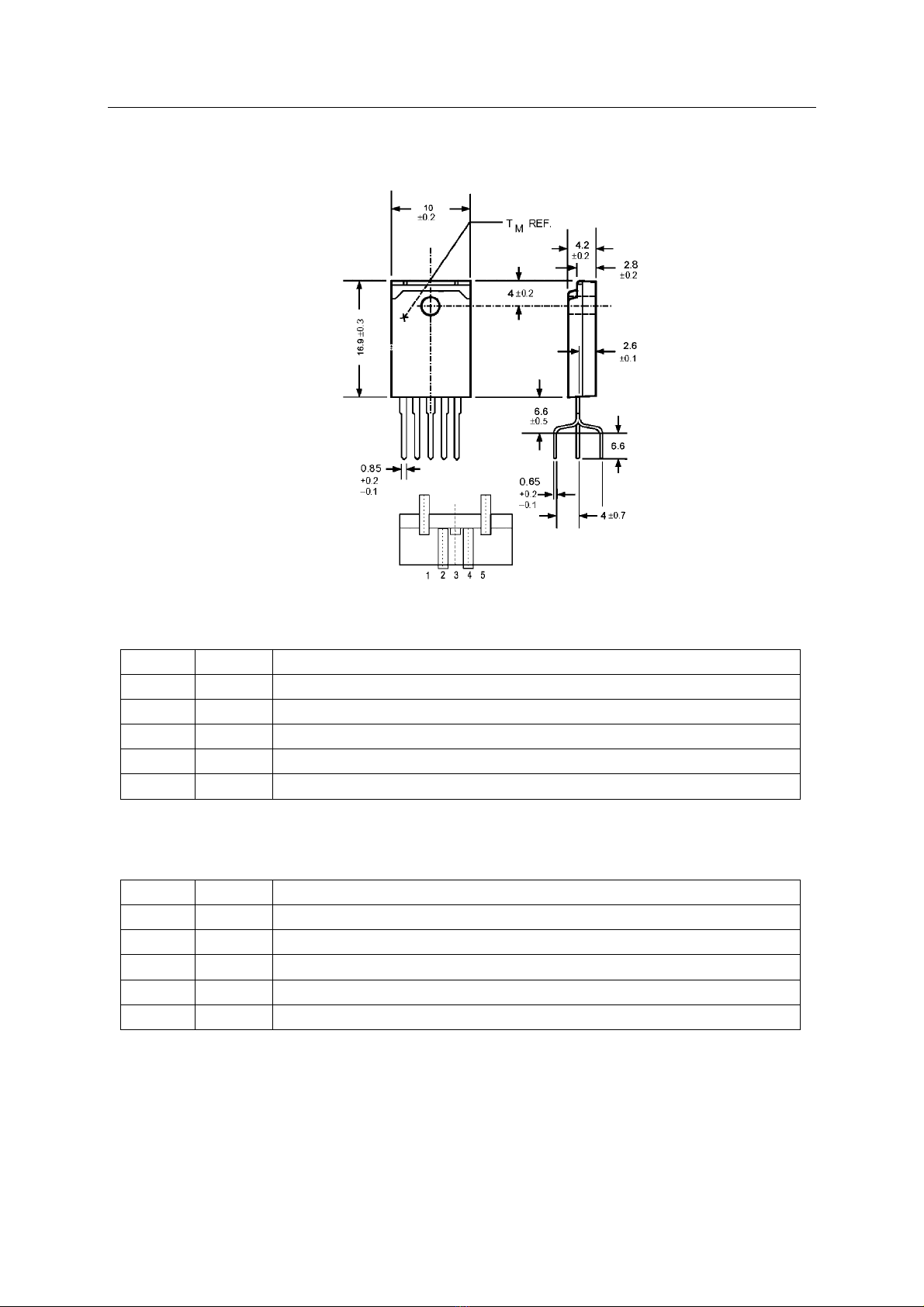
Power Control Circuit STR-G5653 (N802)
The Series STR-G5653/F6654 is specifically designed to satisfy the requirements for increased
integration and reliability in off-line quasi-resonant flyback converters. The series incorporates a
high-precise error amplifying control and drive circuit with discrete avalanche-rated power MOSFET,
featuring fewer external components, small-size and standard power supply.
Covering the power range from below 25 watts up to 300 watts for 100/115/230 VAC inputs, and up to
150 watts for 85 to 265 VAC universal input, these devices can be used in a range of applications,
from battery chargers and set top boxes, to televisions, monitors, and industrial power supply units.
Cycle-by-cycle current limiting, under-voltage lockout with hysteresis, over-voltage protection, and
thermal shutdown protects the power supply during the normal overload and fault conditions.
Low-current startup and a low-power standby mode selected from the secondary circuit completes
a comprehensive suite of features. The series is provided in a five-pin overmolded SIP style package,
affording dielectric isolation without compromising thermal characteristics.
1. Features
·Flyback Operation with Quasi-Resonant Soft Switching for Low Power Dissipation and EMI
·Rugged Avalanche-Rated MOSFET
Soft drive circuit MOSFET
Adjustable MOSFET switching speed
·Choice of MOSFET Voltage and Rds(on)
·Full Over-Current Protection (no blanking)
·Under-Voltage Lockout with Hysteresis
·Over-Voltage Protection
·Direct Voltage Feedback
·Low Start-up Current (100μAmax)
·Low-Frequency, Low-Power Standby Operation
·Overmolded 5-Pin Package
2.Circuit Block Diagram
Fig. 12
16
SERVICE MANUAL
3. Pin Configuration and Functions
Fig. 13
3.1 Pin function for STR-G5653
Pin No. Symbol Function Description
1 D MOSFET drain
2 S MOSFET source
3 GND Ground
4 VIN Supply voltage input for control circuit
5 OCP/FB Over-current protection detection signal/voltage-limiting signal input
3.2 Pin function for STR-F6654
Pin No. Symbol Function Description
1 OCP/FB Over-current protection detection signal/voltage-limiting signal input
2 S MOSFET source
3 D MOSFET drain
4 VIN Supply voltage input for control circuit
5 GND Ground
4. Refer to Table 7 about Functions and Service Data of the IC’s Pins.
17

SERVICE MANUAL
Service Data of Key ICs
Table 2 Functions and Service Data of OM8370(N105)’s Pins
Digital Multimeter
Pin
No. Functions Description Reference
Voltage (V)
Positive Resistance
(20KΩ)
Negative Resistance
(20KΩ)
1 Port 1.3 or counter/timer 1 input 0.8 ∞∞
2 Port 1.6 or I2C-bus clock line 4 .2 6.5 6.0
3 Port 1.7 or I2C-bus data line 4.2 6.5 6.0
4 Port 2.0 or tuning PWM output 1.128 13.1 10.2
5 Port 3.0 or ADC0 input or PWM0 output 0.36 ∞∞
6 Port 3.1 or ADC1 input or PWM1 output 3.29 1.64 1.64
7 Port 3.2 or ADC2 input or PWM2 output 3.29 1.67 1.67
8 Port 3.3 or ADC3 input or PWM3 output 4.91 7.8 7.3
9 Digital ground for µ-Controller core and
periphery 0 0 0
10 Port 0.5 (8 mA current sinking capability for
direct drive of LEDs) 0 7.2 6.99
11 Port 0.6 (8 mA current sinking capability for
direct drive of LEDs) 4.17 7.7 7.3
12 Analog ground of Teletext decoder and
digital ground of TV-processor 0 0 0
13 Internally connected 2.285 ∞0
14 2nd supply voltage TV-processor (+8V) 8.1 1.2 1.4
15 Supply voltage of digital circuit of
TV-processor 4.96 ∞∞
16 Phase-2 filter 3.49 ∞∞
17 Phase-1 filter 3.81 ∞∞
18 Ground 3 for TV-processor 0 0 0
19 Bandgap decoupling 3.96 ∞∞
20 Automatic volume levelling (90° versions) /
E-W drive output (110° versions) 0.78 ∞∞
21 Decoupling sound demodulator (QSS
version in AM/FM mode) 2.3 ∞∞
22 Vertical drive B output 2.3 ∞∞
23 Vertical drive A output 1.85 ∞∞
24 IF input 1 1.85 ∞∞
25 IF input 2 3.82 ∞∞
26 Reference current input 3.75 ∞∞
27 Vertical sawtooth capacitor 1.36 4.75 4.73
28 Tuner AGC output 1.87 ∞∞
29 Audio deemphasis or SIF input 1 1.87 ∞∞
(Continued)
18
This manual suits for next models
3
Table of contents
Other ERISSON TV manuals


