Erone SEL 2641 R433-RM User manual
Thank you for choosing a product Erone. You are recommended to
read carefully this manual before using the product
DI INSTALLAZIONE
MANUAL
INSTALLATION
SEL 2641 R433-RM
ERONE - RADIO PROGRAMMER
FOR ROLLING SHUTTERS AND AWNINGS
RADIOCOMANDI

INDICE
RADIOCOMANDI
2
1- DESCRIPTION
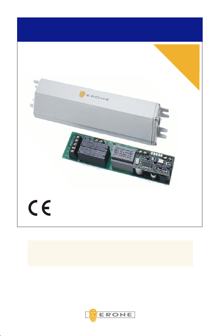
The radio programmer Erone mod.2641R433SV is designed for the control of asyncronous 220V
max 400W tubolar motors for rolling shutters and awnings.
The appliance can operate both with the transmitter Erone mod. SETR264 E2/E4, and with the
wall transmitter mod. Erone SETR264 EM.
The operating frequency is 433.92 MHz.
The “rolling code” c allows to get an high security level and a complete inviolability
of the transmission between transmitter and receiver. In fact, the code emitted by the transmitter
changes at every activation in this way, any risk of copy and scanning.
oding system
avoiding,
2 - TECHNICAL SPECIFICATIONS
RADIOCOMANDI
Fig. 1 - Radio programmer Fig. 2 - Wall transmitter
Receiver’s type Etherodyne
Operating frequency 433.92 MHz
Modulation AM/ASK
Input load 50 Ohm
channel width > 25 KHz
Intermediate frequency 10,7 MHz
Sensitivity -113 dBm
Local oscillator emission < -57 dBm
Power supply 230 Vac / 50 Hz
Consumption at rest 2mA
Motor max power 400 W
Max number of storable codes 100
Max time out 180 sec.
Operating temperature -20°/+70°C
Container Bayblend
Housing protection IP54
Weight 105 gr.
Dimensions 25 x 41 x 154mm
Operating frequency 433.92 MHz
E.r.p. 100 uW
Modulation AM/ASK
64
Code's combinations 2
Power supply 2 x 3 V lithium batteries
Consumption 8,4 mA
Batteries max during 3 years
Weight 47 gr.
Dimensions 80 x 74 x 16 mm
Radio programmer SEL2641R433SEV
TX SETR264EM

RADIOCOMANDI
3
3 - FUNCTIONALITY
3.1OPERATING MODES
!Sequential mode
!Separated commands mode
3.2 TYPE OF COMMAND
!Single command
!Multiple command
!
A transmitter drives many receivers. It is enough to memorise the transmitter into many
receivers. In this case, it is advisable, to use the separated command mode.
Opening, stop, and closing can be done by using the same button of the transmitter.
For the configuration on the receiver see chapter 5 of this manual. In the sequential mode, it
is possible to drive 4 rolling shutters with the same radio command.
In this mode for each function it is used a different button, so are used 3 of the 4
buttons of the transmitter.
A transmitter drives a single tubular motor.
Different transmitters command the same receiver. Are possible up to 100 radio
commands, each of which operate in a sequential mode, and up to 33 radio commands
that operate with separated commands. It is, also, possible the combination of single
and multiple modes.
General or group command
4 - INSTALLATION
4.1 ALLOCATION
The choice of the site, for the radio programmer is very important for the best result of your
system.The following notes should to be followed:
!Place the device far from all the possible interference sources, information systems, alarm
systems, radio emissions.
!The distance between 2 radio programmers has to be greater than 1,5mt.
4.2 FIXING
Fix the container using the supports with the appropriate
screws depending upon the nature of the support.
In case of installations inside the rolling shutter box, make
the connections before positioning.
Fig. 3
This appliance has the CLASS II Classification ( ) as concerns the protection against the
electric shock , as indicated by the European Standard EN 60335-1: Sept 1994 : "Safety of
household and similar electrical appliances, Part 1 : General Requirements ".

RADIOCOMANDI
4
4.3 CONNECTIONS
Connect the appliance to the supply by means a device having a contact separation of at
least 3 mm in all poles.
Before any connection be sure that the power is interrupted.
Pass the cables through the holes of the box cover and the gasket (in case of
hermetical closing).
Power supply 230 Vac
Clamp 1 Phase Input
Clamp 2 Neutral Input
Clamp 7 Earth Input
Asyncronous tubolar motor
Clamp 3 Closing Output
Clamp 4 Common Output
Clamp 5 Opening Output
Clamp 6 Earth Output
Anemometer ( not polarised)
Clamp 8 Input 1
Clamp 9 Input 2
Aerial
Clamp 10 Net Input
Clamp 11 Shield Input
Recommended cables section
2 2
Power cable: 3 x 1 mm Anemometer cable : 2 x 0.75 mm
2
Tubolar motor cable: 4 x 1mm Aerial (optional): RG58
4.4 ADVISABLE PROCEDURE
Once completed the fixing of the mechanics (rolling shutter or awning) identify the connections of
the motor that has to unroll the awning or the rolling shutter.
The net C of the motor will be connected to the clamp 4 (common); the net that makes the unroll of
the awning has to be connected to the clamp 3 (closing).
The last motor cable has to be connected to the clamp 5 (opening).
In this way it is created the following correspondance:
KEY B: unroll of the awning or opening rolling shutter
KEY D: roll of the awning or closing rolling shutter
By means of this procedure the anemometer is always connected to the key B and operates always
the unroll of the awning.
Attention:
If you don't respect the last indication, (only in case of awning), there is the risk of an
intervention of the anemometer when the awning is completely closed.
Fig. 4
Fig. 5
ANEM.
Connect the cables to the correspondent terminal blocks according to the following table:

RADIOCOMANDI
5
5 - PROGRAMMING
5.1 SYMBOLOGY
The installation phases are shown by using the following symbology:
Pressure for 4
seconds
Pressure for 1
second
Bip Short bip of the buzzer
Biiiiiiiiiiiiiiip Long bip of the buzzer
Bip - Bip - Bip Sequence of 3 short bips
It is advisable to fix the transmitters to the wall after the programmation, because during
this phase, the sensitivity of the receiver is reduced and the range of the transmitter as
well.
5.2 TRANSMITTER MEMORISATION
During the first installation it is necessary to power just one receiver at a time in order to
avoid multiple memorisations of the same transmitter into different receivers.
Identification radio command's keys
C4 = Push key C for 4 seconds
A1 = Push key A for 1 second
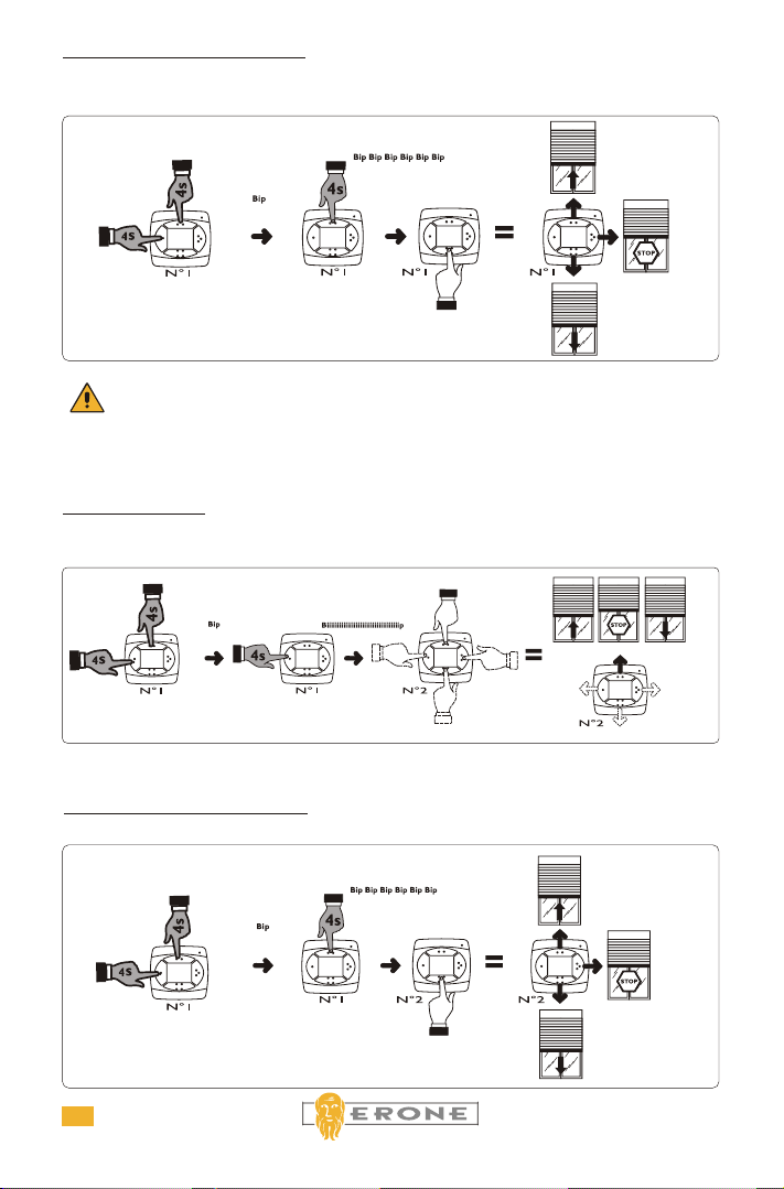
Memorisation of first transmitter (N°1) on a receiver
Sequential mode:
(A+B)4 [Bip], A4 [Biiiiiiiiiiiiiip] , A1, or B1, or C1, or D1.
Bip - Bip - ...... - Bip Repeated bip of the buzzer
(1)C4 = Push key C of transmitter N°1 for
4 seconds
Fig. 6
Fig. 7
Biiiip Medium bip of the buzzer
(A+B)4 = Push at the same time the keys A and
B for 4 seconds
RADIOCOMANDI
6
It is highly advisable to memorise at least 2 transmitters in each receiver, to prevent a
transmitter fealure.
"Separated commands" mode:
(A+B)4 [Bip] - B4 [Bip -Bip - ......... - Bip ] , D1.
IThe first transmitter is indispensable for the memorisation of further radio commands.
Memorisation of further transmitter (Es.N°2) on the same receiver
Sequential mode:
(1)(A+B)4 [Bip] - (1)A4 [Biiiiiiiiiiiiiip] , (2)A1, or (2)B1, or C1, or D1.(2) (2)
Memorisation of further transmitter (Es. N°2) on the same receiver.
[Bip -Bip - ......... - Bip ] , (2)D1.
"Separated commands" mode:
(1)(A+B)4 [Bip] - (1)B4
Fig. 10
Fig. 8
Fig. 9
RADIOCOMANDI
7
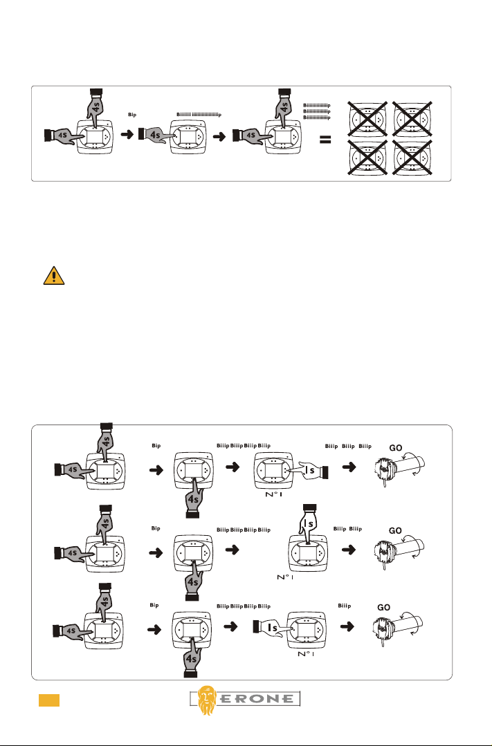
5.4 MEMORY ERASE
5.4.1Using the radio control
(A+B)4 - [Bip] A4 [Biiiiiiiiiiiiiiiiiip ] - (A+B)4 [Biiiip ],[Biiiip ],[Biiiip ].
ATTENTION: DO THIS OPERATION WITHOUT SLIDING OUT THE ELECTRONIC
CARD FROM THE BOX !!.
OPERATE EXCLUSIVELY FROM OUTSIDE !.
5.5 TIME OUT SETTING
(A+B)4 [Bip], D4 [Biiip - Biiip - Biiip - Biiip] and following:
A1 [Biiip] : for time-out of 40 Sec.
B1 [Biiip, Biiip] : for time-out of 90 Sec. (default value)
C1 [Biiip, Biiip, Biiip] : for time-out of 180 Sec.
The time out setting allows to stop the motor in case of failure of the limit switches.
This operation has to be done by using the transmitter according the following sequence:
5.4.2 -Using the reset push - button
Make a pressure on the button of the plastic box of the radio programmer up to the biiiiiiiiiiip of
the buzzer.
In this way the reset push button present on the bottom side of the electronic card is activated.
Afterword release and within 2 seconds push again the button of the box up to listen 3 long
biiiiiips of the buzzer which give the cancelling confirmation.
90 sec
.
180 sec
.
40 sec
.
Fig. 11
Fig. 12

The guarantee period of all Erone products is 24 months, beginning from the
manufacture date. During this period, if the product does not work correctly, due
to a defective component, the product will be repaired or substituted at the
discretion of the producer. The guarantee does not cover the plastic container
integrity. After sale service is supplied at the producer's factory.
ERONE is a trademark by ELPRO INNOTEK S.r.l.
Via Piave, 23 - I-31020 S.Pietro di Feletto (TV) - ITALY
Tel. +39.0438.450879 - Fax. +39.0438.457126
E-Mail: info @erone.com
Web: www.erone.com
RADIOCOMANDI
8
IS-RSVERUK Rev. 4 del 17.10.2001
5.6 ANEMOMETER INTERVENTION SPEED SETTING
(A+B)4 [Bip], C4 [Bip - Bip - Bip] and following:
A1 [Bip] : for 20 Km/h ( default value )
B1 [Bip, Bip] : for 30 Km/h
C1 [Bip, Bip, Bip] : for 40 Km/h
D1 [Bip, Bip, Bip, Bip] : for 50 Km/h or more.
It is possible to set the speed of the wind at which the awning automatically closes. The default
value is 20 Km/h. The operation can be done only with a transmitter already memorised.
Fig. 13
5.7 TEST ANEMOMETER
It allows to verify the correctness of the connection with the anemometer without having to
simulate the intervention of the wind.
(A+B)4 [Bip], D4 [Biiiip - Biiiip - Biiiip, Biiiip], D1 [Biiiip, Biiiip, Biiiip, Biiiip]
To this point, making to
manually turn the shovels of the
anemometer, some beeps of
confirmation are emitted by the
buzzer. The exit from the phase
of test anemometer effects with
a pressure of the keys A., B or D
Fig. 14
Table of contents
Other Erone Motherboard manuals

Erone
Erone SEL2641R433-P7 Technical specifications

Erone
Erone 024A Series Technical specifications

Erone
Erone SEL2641R433-PT Technical specifications

Erone
Erone SEP230M2 Series Technical specifications

Erone
Erone SEL2641R433-P7P Technical specifications

Erone
Erone SEL2641R433-P4P Technical specifications

Erone
Erone SEL2641R433-P4 Technical specifications


