Erone SEL2641R433-PT Technical specifications

SEL2641R433-PT , SEL39R433-PT, SEL39R30-PT
Ricevitore di potenza temporizzato
Radioprogrammer 2KW
Récepteur éclairage 2KW
Leistungsempfänger 1Kanal 2KW
Manuale d’installazione ed uso - Italiano ............Pag. 4
Use and installation Manual - English .................Pag. 7
Notices d’installation et utilisation - Français .....Pag. 10
Pag. 13Bedienungsanleitung - Deutsch ...........................
THE SMART LIVING
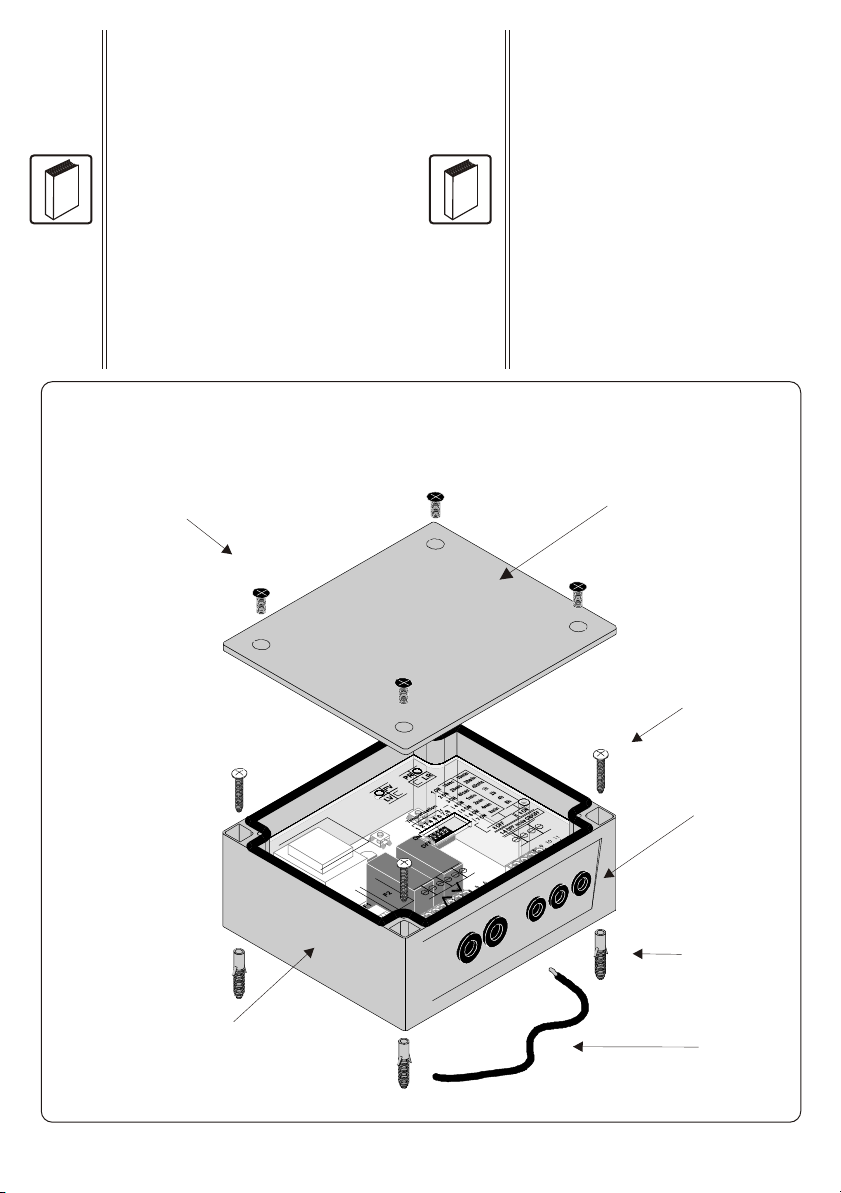
4 viti per fissaggio del coperchio
4 screws for cover fixing
4 vis capot
4 Schraube
Coperchio
Cover
Couvercle
Deckel
Scatola con ricevitore e coperchio di protezione in plexiglass
Receiver box with plexiglas cover
Boîtier avec récepteur et plexiglas de protection
Behälter mit Funkmotorsteuerung
Antenna
Aerial
Fil d’antenne
Antenne
4 tasselli
4 plugs
4 chevilles
4 Einsatz
4 Viti per fissaggio della scatola
4 screws for box fixing
4 vis de fixation
Schraube
Fig. 1
Pag. 2
Presentazione / Introduction / Introduction / Allgemein
Dichiarazione di Conformità:
Il costruttore Elpro Innotek Spa dichiara che il ricevitore
mod. SEL2641R433-PT, SEL39R433-PT, SEL39R30-PT è
conforme alle Direttive Europee 73/23/CEE, 89/336/CEE
e 99/05/CE.
Declaration of Conformity:
Elpro Innotek Spa as manufacturer declares that the
following appliances : SEL2641R433-PT, SEL39R433-PT,
SEL39R30-PT fullfil the requirements of the European
Directives 73/23/CEE, 89/336/CEE and 99/05/CE.
Déclaration de Conformité:
Elpro Innotek Spa déclare que les appareils SEL2641R433-
PT, SEL39R433-PT, SEL39R30-PT sont conformes aux
exigences essentielles et autres dispositions des Directives
73/23/CEE, 89/336/CEE e 99/05/CE.
Declaration of Conformity:
SEL2641R433-PT, SEL39R433-PT,
SEL39R30-PT)
Der Empfänger ( typ
entspricht den europäischen Normen
89/336/CEE 73/23/CEE, 99/05/CE, EG
Konformitätsbescheinigung.
?
Misure di sicurezza
Per un perfetto funzionamento dell’apparecchio, si prega di
leggere interamente questo manuale e seguire attentamente
le indicazioni ivi descritte, in quanto l’uso improprio può
danneggiare l’apparecchio
Security measures
For a perfect functioning of the device, read carefully this
manual and follow all the indications, since an inadeguate
use can make damages to the device
Mesures de sécurité
Pour un fonctionnement parfait de l’appareil, vous devez
lire complétement les instructions de installation et suivre
estrictement les indications décrites, puisque un maniement
inadéquat peut produire dommage à l’appareil.
Sicherheitsmaßnahmen
Um ein einwanfreies Functionieren des Apparates zu
erhalten, sollten Sie die in der Bedienungsanleitung
enthaltene Anweisungen zur Bedienung und zur Installation
genau durchlesen und befolgen, da eine Nichtbeachtung
derselben starke Schäden am Apparat hervorrufen kann.
Passacavi
Wire leads
Passes-fils
Kabelführung
?

Fig. 2
Trasformatore di alimentazione
Transformer
Transformateur
Trasformator
Tasto PV - LV
Push-button PV - LV
Touche PV - LED LV
Taster PV - LED LV
LED
LED
Dip-switch 6 vie
Dip-switch
Dip-switch
Dip-switch zur programmierung
Morsettiere di I/O
Terminal boards
Bornes
Anschlüsse
52
140
115
128
104
Tasto PR - LR
Push-button PR - LR
Touche PR - LED LR
Taster PR - LED LR
LED
LED
Fig. 3
Fig. 4
Pag. 3
Dimensioni d’ingombro / Overall
dimensions Dimensions
d’encombrement / Abmessung
Interassi / Drilling distances
Distances de perçage / Spurweiten
Layout
Fusibile F2 : 10A - 250V
Fuse F2 : 10A - 250V
Fusible F2 : 10A - 250V
Sicherung A - 250VF2 : 10
54321
ON
6 7 8
7 98 10
Ph Ph
1 2 3 4
5 6
N N
PR
LR
PV
LV
OFF
F1
ON
Temporisation
1
1 ON 10sec
20sec
40sec
1min
2min
4min
8min
10min
20min
40min
1h
2h
4h
2 ON
3 ON
4 ON
5 ON
6 ON
7 ON
23 4 5 76 8
IN OUT
8h
8 OFF
1-8 OFF mode ON/OFF
8 ON
Buzzer

ITALIANO
1 - DESCRIZIONE
2 - CARATTERISTICHE TECNICHE
Il ricevitore di potenza temporizzato ERONE 2000W è un radio
ricevitore in grado di azionare direttamente un carico resistivo
( es. per illuminazione ) con potenza max di 2000 W.
ERONE30(DP/SL) SEL 39 R30PT 30.875 MHz Dip/Self learning
ERONE433DP SEL 39 R433PT 433.92 MHz Dip-switch
La frequenza
di ricezione e la codifica variano a seconda del modello.
La seguente tabella riassume i sequenziali della gamma Erone
evidenziandone serie, modello, frequenza e tipo di codifica:
SERIE MODELLO FREQUENZA CODIFICA
ERONE433 SEL 2641 R433PT 433.92 MHz Rolling code
A seconda della frequenza e della codifica, il ricevitore funziona
con differenti modelli di trasmettitori ERONE, secondo la tabella
seguente:
Modello Sequenziale Trasmettitori impiegabili
SEL 2641 R433PT S2TR2641E2/E4- E4
SETR2641AM2
SETR2641-TM
SEL39 R30PT SETL 39E2/E4
SETD 39E2/E4
SEL 39 R433PT SETDS39433 E2/E4
Modelli SEL 2641R433-PT / SEL39R433-PT
Tipo ricevitore Supereterodina
Frequenza portante 433,92 MHz
Frequenza oscillatore locale 6,6128 MHz
Modulazione AM/ASK
Impedenza d'ingresso 50 Ohm
Frequenza intermedia 10,7 MHz
Sensibilità d'ingresso -115 dBm
Emissione dell'oscillatore locale < -57 dBm
Tensione di alimentazione 230 Vac
Potenza massima del carico 2000 W
Capacità di memoria 85 / 100
Temporizzazione 10 sec. - 16h, 10 min
Temperatura di funzionamento -20°/+70°C
Grado di protezione IP44
Peso 380 gr.
Dimensioni 140 x 115 x 52 mm
Modello SEL39R30-PT
Tipo ricevitore Supereterodina
Frequenza portante 30,875 MHz
Frequenza oscillatore locale 30,420 MHz
Modulazione AM/ASK
Impedenza d'ingresso 50 Ohm
Frequenza intermedia 455 KHz
Sensibilità d'ingresso -117 dBm
Emissione dell'oscillatore locale < -57 dBm
Tensione di alimentazione 230 Vac
Potenza massima del carico 2000 W
Temporizzazione 10 sec. - 16h, 10 min
Capacità di memoria 100
Temperatura di funzionamento -20°/+70°C
Grado di protezione IP44
Peso 380 gr.
Dimensioni 140 x 115 x 52 mm
3 - FUNZIONALITA'
Il ricevitore permette di comandare l'accensione e lo spegnimento
di un carico resistivo ( ad es. per illuminazione ) di potenza
massima di 2KW
I modi di funzionamento sono i seguenti:
!Acceso / Spento
Un primo impulso permette l'accensione della luce,
un secondo impulso ne provoca lo spegnimento.
!Temporizzato
Un impulso permette l'accensione della luce; lo spegnimento è
automatico temporizzato, regolabile da 10 Sec. a 16h e10min
per mezzo di un dip-switch.
Durante la temporizzazione è possibile lo spegnimento anche
mediante radiocomando.
E' inoltre possibile collegare un pulsante esterno (N.A.) tra i
morsetti 7-8 o un contatto a chiave.
Ad ogni accensione del ricevitore si accende il led LA collocato in
prossimità dei relè.
4 - INSTALLAZIONE
Posizionamento
La scelta della posizione del ricevitore è molto importante per
ottenere un buon funzionamento del sistema.
Devono essere rispettate le seguenti condizioni:
- posizionare il ricevitore lontano da fonti di disturbo quali sistemi
informatici, allarmi o altre emissioni radio.
- la distanza tra due ricevitori deve essere superiore a 1.5 metri.
Fissaggio
Togliere il coperchio dal ricevitore. Fissare la scatola ad ogni
angolo utilizzando viti e fisher in dotazione o con viti appropriate
alla natura del supporto.
Ph
1 2 5
N
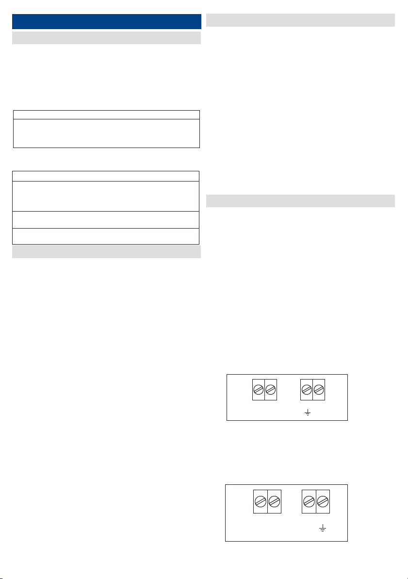
Connessioni
1- Collegare l'alimentazione ai morsetti corrispondenti (fig. 5):
morsetto 1 = PH fase
morsetto 2 = N neutro
morsetto 5 = terra
2 - Collegare il carico ai morsetti corrispondenti (fig. 6):
morsetto 3 = N neutro
morsetto 4 = PH fase
morsetto 6 = terra
3 4 5 6
NPh
Fig. 6
Fig. 5
Pag. 4
6
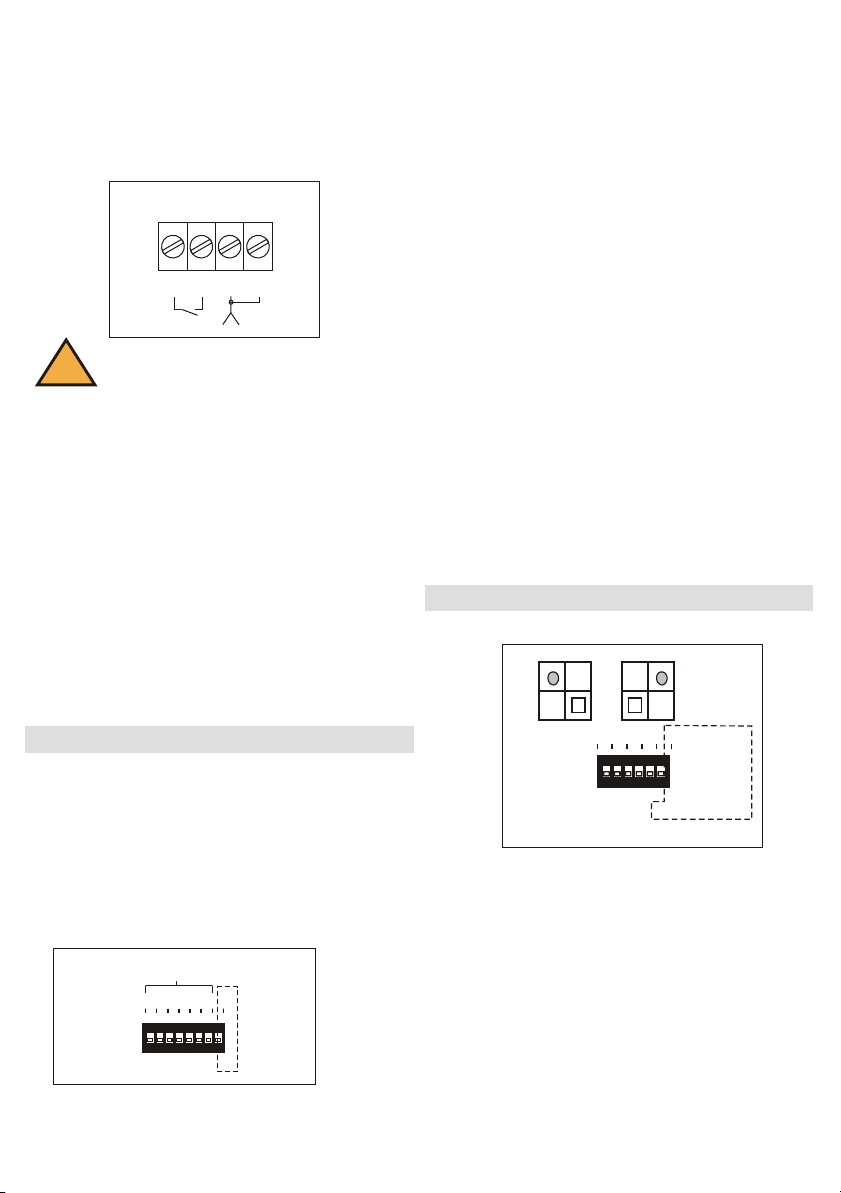
3-Collegare gli accessori come segue (fig. 7):
- se collegate un'antenna (non in dotazione), collegare la calza al
morsetto 9, ed il centrale al morsetto 10; oppure collegare il filo
d'antenna in dotazione al morsetto 9.
- se collegate un dispositivo di comando (non in dotazione),
collegare il contatto normalmente aperto e impulsivo tra i morsetti 7
e 8;
7 98 10
Fig. 7
!Togliere tensione prima di sollevare il plexiglas di
protezione e prima di intervenire sulla morsettiera
5 - SCELTA DEL MODO DI FUNZIONAMENTO
Fig. 8
Pag. 5
Fusibile
Il fusibile da 10 A fornito è destinato alla protezione di carichi con
potenze di 2000W Per carichi inferiori è consigliabile adattare il
fusibile alla potenza utilizzata applicando la formula seguente:
Corrente max fusibile = (Potenza in W del carico da comandare )
/ (Tensione di alimentazione di 230V)
Esempio:
Per comandare una illuminazione di 500 W occorrerà un fusibile
di :
500/230 = 2,17 A
Utilizzare perciò un fusibile da 2,5A
La temporizzazione viene impostata per mezzo di un dip-switch
binario ad 8 vie ( Figura 8).
Se tutti i dip-switches sono posizionati su OFF la temporizzazione è
esclusa ed il ricevitore funziona in modo acceso/spento.
Nel caso in cui almeno uno dei dip è posizionato su ON la
temporizzazione è abilitata.
Ciò significa che a seguito di un'accensione effettuata a mezzo
radiocomando, o pulsante esterno, l'illuminazione si spegnerà dopo
un certo intervallo di tempo.
54321
ON
678
OFF
ON
1 2 3 4 5 76 8
54321
ON
678
OFF
ON
1 2 3 4 5 76 8
54321
ON
678
OFF
ON
1 2 3 4 5 76 8
54321
ON
678
OFF
ON
Temporizzazione
1 2 3 4 5 76 8
Il dip-switch n° 8 permette di moltiplicare per 60 il valore di
tempo selezionato dai dip-switches precedenti.
In base a ciò è possibile determinare la temporizzazione voluta
secondo la tabella seguente :
Switch 8 ad OFF
Switch 1 su ON = 10 sec.
Switch 2 su ON = 20 sec.
Switch 3 su ON = 40 sec.
Switch 4 su ON = 1 min.
Switch 5 su ON = 2 min.
Switch 6 su ON = 4 min.
Switch 7 su ON = 8 min.
Switch 8 ad ON
Switch 1 su ON = 10 min.
Switch 2 su ON = 20 min.
Switch 3 su ON = 40 min.
Switch 4 su ON = 1 h.
Switch 5 su ON = 2 h.
Switch 6 su ON = 4 h.
Switch 7 su ON = 8 h.
NOTA : Posizionando più dip-switch ad ON i tempi si sommano
Esempio:
Temporizzazione di 50 Sec.
switch ad ON : 1, 3
switch ad OFF : 2,4,5,6,7,8,
6 - MEMORIZZAZIONE DEI TRASMETTITORI
654321
ON
PR
LR
PV
LV
ON
1 2 3 4 5 6
OFF
Fig. 9
Memorizzazione TX
La memorizzazione dei trasmettitori si effettua autoapprendimento
mediante il pulsante PR del ricevitore.
Premere e mantenere premuto il pulsante PR, il led rosso si accende;
rilasciare il pulsante e premere entro 4 sec. il pulsante del
trasmettitore che si desidera memorizzare, il led rosso LR si spegne e
scatta il relè per conferma dell'avvenuta memorizzazione.
Cancellazione dei trasmettitori dalla memoria
Premere PR fino a quando il led rosso si accende, rilasciare PR poi, di
seguito premere PR e PV contemporaneamente fino a quando i due
led lampeggiano per 3 volte.
In questo modo tutti i codici vengono cancellati dalla memoria.
7 - CANCELLAZIONE
8 - GESTIONE CONDOMINIALE
Per utilizzare la gestione dei codici, è necessario prendere nota in
quale cella di memoria il codice di ciascun trasmettitore è
memorizzato ed a quale relè è associato.
La gestione dei codici è utile nel caso di memorizzazioni di molti
trasmettitori nel ricevitore, in una installazione condominiale (es.:
100 trasmettitori memorizzabili nelle celle da 1 a 100).
La posizione della memoria è indicata attraverso una sequenza
binaria a 7 bit.
Per prendere nota della posizione bisogna riferirsi alla tavola di
corrispondenza seguente osservando la posizione nella sequenza
del led verde LV:
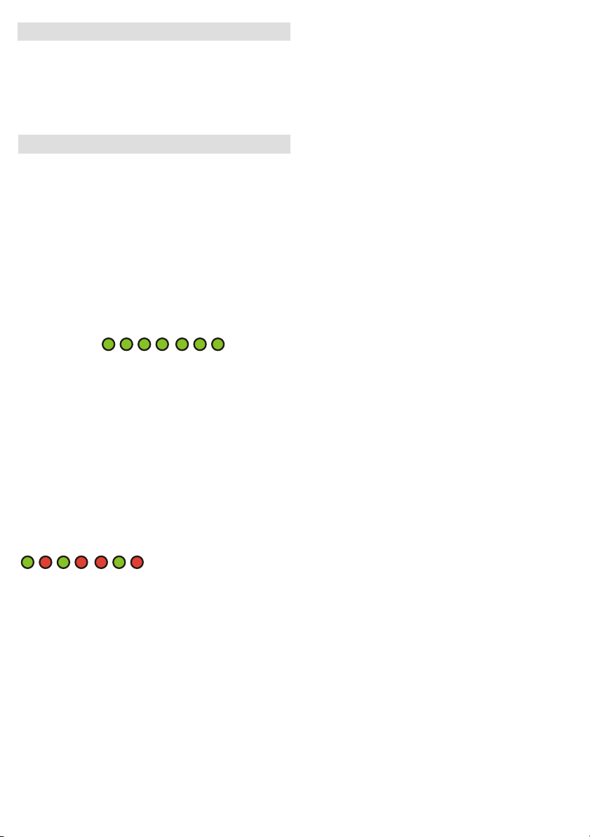
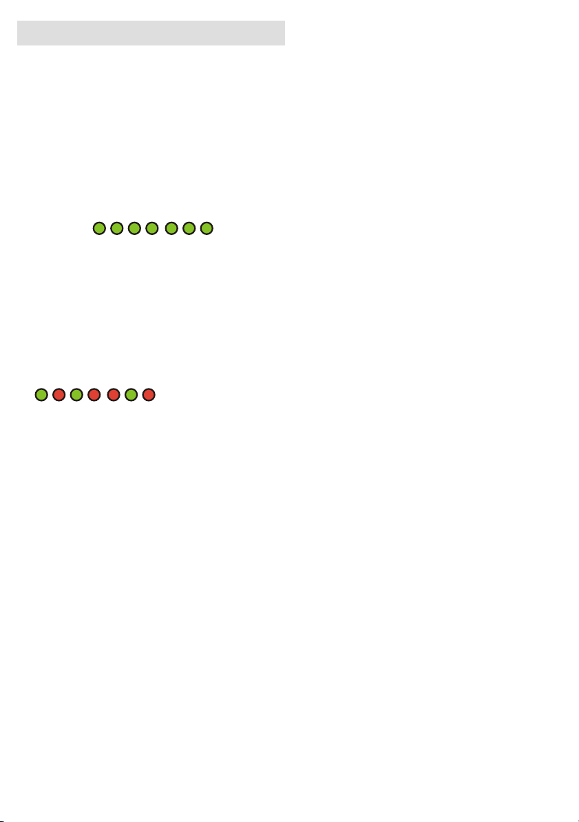
codice 7bit 1 2 3 4 5 6 7
LV
corrispondenza 1 2 4 8 16 32 64
Bisogna tenere conto soltanto delle accensioni del led verde,
essendo il led rosso uguale allo zero.
ESEMPIO : Lettura dei led per la posizione 37 della memoria:
1a accensione: led verde
2a accensione: led rosso
3a accensione: led verde
4a accensione: led rosso
5a accensione: led rosso
6a accensione: led verde
7a accensione: led rosso
1 2 3 4 5 6 7
1 2 4 8 16 32 64
1 + 0 + 4 + 0 + 0 + 32 + 0 = 37
Verifica del numero dei trasmettitori
memorizzati
Sul ricevitore, entrare in modo programmazione premendo PR
finchè LR si accende. Rilasciare PR e ripremere PR per un secondo.
A partire da questo momento, i led lampeggiano formando la
sequenza a 7 bit di cui al numero precedente.
Il totale ricavato con la tabella di corrispondenza indica la quantità
di trasmettitori memorizzati.
Sostituzione di un codice in memoria
E' possibile cancellare un codice trasmettitore dalla memoria,
memorizzandone un altro nella stessa posizione.
Per far ciò è necessario conoscere la posizione di memoria del
trasmettitore da sostituire.
Questa operazione può essere fatta seguendo le indicazioni
riportate nel paragrafo precedente "Verifica della posizione di un
codice trasmettitore in memoria".
Una volta nota la posizione di memoria da sostituire, procedere nel
modo seguente:
- Sul ricevitore, premere PR fino a quando il led corrispondente si
accende; rilasciare PR.
- Premere PV per almeno un secondo;
-Comporre di seguito, entro 2 secondi, la sequenza binaria di 7 bit
premendo PR e PV, relativa alla posizione di memoria da sostituire.
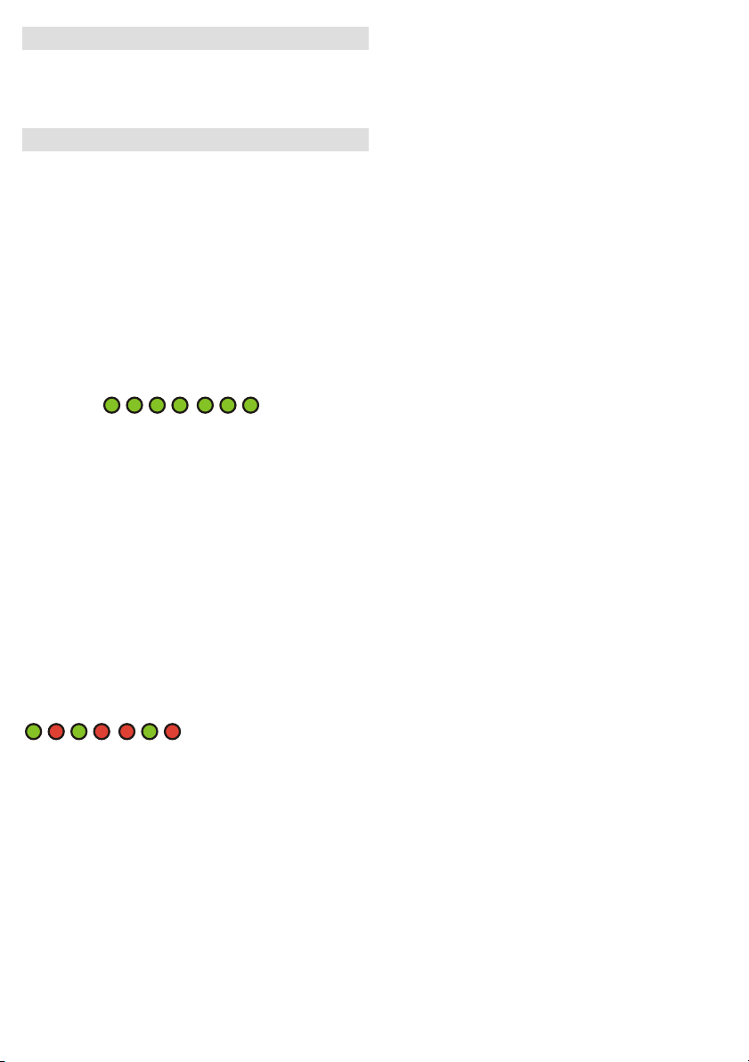
Esempio di posizionamento sulla 42 esima cella di memoria:
LR LV LR LV LR LV LR
0 2 0 8 0 32 0
0 + 2 + 0 + 8 +0 + 32 +0 = 42
Premere in perciò sequenza:
PR, PV, PR, PV, PR, PV, PR.
A partire da questo momento il led rosso LR si accende a conferma
dell'ingresso in modo programmazione.
Premere entro 4 secondi il pulsante ( A, B, C o D ) del trasmettitore da
memorizzare.
Il led rosso LR si spegne confermando l'avvenuta sostituzione.
In questo modo il vecchio codice viene cancellato e il ricevitore
risponde al nuovo codice memorizzato.
- è possibile utilizzare sempre lo stesso trasmettitore (es.: il
trasmettitore utilizzato per la manutenzione dell'impianto, per
cancellare i codici utenti).
Memoria piena
Quando la memoria è piena, cioè quando le 85 o 100 celle di
memoria ( in relazione al modello utilizzato ) sono occupate, i led
rosso LR e verde LV lampeggiano 3 volte contemporaneamente
quando si entra in programmazione; il led corrispondente al led
sollecitato resta quindi acceso per 4 secondi (modo di
programmazione) al fine di permettere l'eventuale cancellazione di
un trasmettitore già memorizzato (vedi paragrafo precedente).
Pag. 6
Verifica della posizione di un codice
trasmettitore in memoria
Premere sul pulsante del radiocomando che si desidera controllare e
rilasciare. Di seguito premere il pulsante PR del ricevitore per almeno
un secondo. A partire da questo istante i led lampeggiano formando
una sequenza di 7 bit, così come descritto precedentemente.
In base ad essa è possibile risalire alla posizione di memoria del
trasmettitore utilizzando il sistema descritto a lato.

ENGLISH
The timered power receiver ERONE 2000W is a radio receiver
which can drive directly a resistive load ( es. for lighting) with max
power of 2000 W. The operating frequency and the coding system
are different, depending upon the model.
The following table summarises the range of Erone radio
receivers, pointing out series, frequency and coding system:
ERONE30(DP/SL) SEL 39R30PT 30.875 MHz Dip/Self learning
ERONE433DP SEL 39R433PT 433.92 MHz Dip-switch
SERIES TYPE FREQUENCY CODING
ERONE433 SEL 2641R433PT 433.92 MHz Rolling code
Depending upon the frequency and the coding, the receiver
operates with different transmitters ERONE, according to the
following table:
SEL 39 R433PT SETDS39433 E2/E4
Receiver Type Usable transmitter
SEL 2641 R433PT S2TR2641E2/E4
SETR2641AM2
SETR2641-TM
SEL39 R30PT SETL 39E2/E4
SETD 39E2/E4
1 - INTRODUCTION
Type SEL 2641R433-PT / SEL39R433-PT
Receiver type Superheterodyne
Carrier frequency 433,92 MHz
Local oscillator frequency 6,6128 MHz
Modulation AM/ASK
Input load 50 Ohm
Intermediate frequency 10,7 MHz
Input sensitivity -115 dBm
Local oscillator emissions < -57 dBm
Power voltage 230 Vac
Load maximum power 2000 W
Temporization time 10 sec - 16, 10min.
Memory capacity 85 / 100
Operating temperature -20°/+70°C
IP grade IP44
Weight 380 gr.
Overall dimensions 140 x 115 x 52 mm
Type SEL39R30-P4
Receiver type Superheterodyne
Carrier frequency 30,875 MHz
Local oscillator frequency 30,420 KHz
Modulation AM/ASK
Input load 50 Ohm
Intermediate frequency 455 KHz
Input sensitivity -115 dBm
Local oscillator emissions < -57 dBm
Power voltage 230 Vac
Motor maximum power 2000 W
Temporization time 10 sec - 16, 10min.
Memory capacity 100
Operating temperature -20°/+70°C
IP grade IP44
Weight 380 gr.
Overall dimensions 140 x 115 x 52 mm
2 - TECHNICAL SPECIFICATIONS
4 - INSTALLATION
3 - FUNCTIONALITY
Operating Modes
The receiver can switch ON and OFF a resistive load ( for lighting
i.e.) with a maximum power of 2KW
The operating modes are as follows:
!ON / OFF
One pulse switches on the light, the next pulse switches it off.
!Timered
One pulse switches on the light. The switching off is automatic,
with a programmable delay adjustable from 10 Sec up to
16h10min by means of an 8 way dip-switch.
During the delay it is possible to switch off the light by means of a
radio transmitter as well.
It is also possible to connect an external push-button (N.O.) or a
key-contact as radiocontrol completion.
The memory capacity is 85 or 100 transmitters.
Positioning
The local choice is very impotant for the best result of the installation.
The following conditions have to be followed:
- Fix the radioprogrammer far from the interference sources as
informatic systems, alarm systems or other radio emissions.
- The distance between 2 receivers should be greater of 1.5 mt.
Fixing
Remove the cover of the receiver; fix the box in each corner by
using the screws and the plugs supplied.
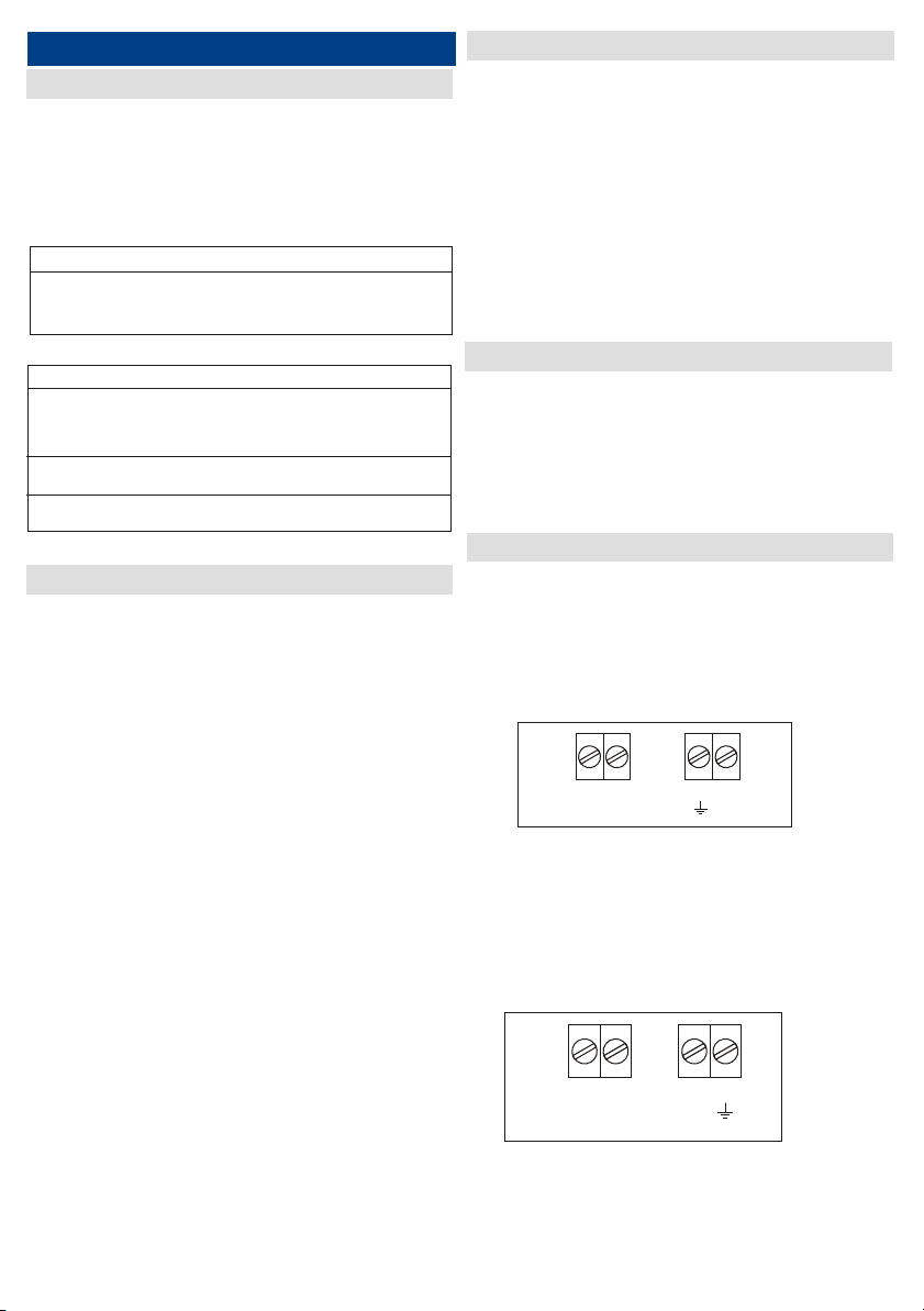
Connections
1- Connect the power supply (230 Vac) to the terminal blocks (fig.
10):
terminal 1 = PH phase
terminal 2 = N neutral
terminal 5 = earth
Fig.10
2 - Connect the load to the terminal blocks (fig. 11):
terminal 3 = N neutral
terminal 4 = Ph Phase
terminal 6 = Earth
Pag. 7
Fig. 11
Ph
1 2 5
N
6
3 4 5 6
NPh

!
Fig. 12
Remove the power before to pick - up the
protection plexiglass and operate on the
terminal blocks.
5 - TIMER SETTING
6 - TRANSMITTER CODES MEMORISATION
654321
ON
PR
LR
PV
LV
ON
1 2 3 4 5 6
OFF
Fig. 14
Pag. 8
3-Connect the accessories as follows (fig. 6):
- if you want to use an antenna,( not supplied), connect the
shield to the terminal 10 and the net to the terminal 9,
otherwise if you use the antenna cable supplied, connect it to
the terminal 9.
- if you want to connect an external command device (not
supplied), connect the N.O. contact to the terminals 7 and
8.
7 98 10
Contact Antenna
FUSE
The supplied 10 A fuse is calculated for the protection of loads
with 2000 W.
For lower power loads, it is advisable to adapt the fuse to the used
power, by using the following formula:
Max fuse current = (power in W of the load to drive ) / (supply
voltage of 230V)
Example:
For the command of a 500 W light, it will be necessary a fuse of:
500/230 = 2,17 A
Use then a fuse of 2,5A.
The timing can be set by means of a binary 8 way dip-switch ( Fig. 8)
If all dip-switches are positioned on OFF the temporisation is
excluded and the receiver operates in ON/OFF mode.
If at least one of the dip is in ON position, the temporisation is active.
This means that after a switching-on performed by radiocommand,
the switching off will occur after a time delay.
The dip-switch N°8 allows to multiply by 60 the time value set by
the dip-switches 1-7
In this way, it is possible to calculate the set up timing according
the following table:
Switch 8 at OFF
Switch 1 at ON = 10 sec.
Switch 2 at ON = 20 sec.
Switch 3 at ON = 40 sec.
Switch 4 at ON = 1 min.
Switch 5 at ON = 2 min.
Switch 6 at ON = 4 min.
Switch 7 at ON = 8 min.
Switch 8 at ON
Switch 1 at ON = 10 min.
Switch 2 at ON = 20 min.
Switch 3 at ON = 40 min.
Switch 4 at ON = 1 h.
Switch 5 at ON = 2 h.
Switch 6 at ON = 4 h.
Switch 7 at ON = 8 h.
NOTE : If more then one dip is positioned at ON, the resulting time
become the sum of each single time.
Example:
Temporisation of 50 Sec.
switches at ON : 1, 3
switches at OFF : 2,4,5,6,7,8.
54321
ON
678
OFF
ON
1 2 3 4 5 76 8
54321
ON
678
OFF
ON
1 2 3 4 5 76 8
54321
ON
678
OFF
ON
1 2 3 4 5 76 8
54321
ON
678
OFF
ON
Temporisation
1 2 3 4 5 76 8
Fig.8
TX Memorisation
The method for the TX memorisation operates in
selflearning mode.
Push and keep pushed the button PR until the red led turns on; release
the button and press within 4 seconds the button of the transmitter to
memorise; the red led LR will turn off and the relay will exite for a while
to confirm the successfully operation.
Push PR and keep it pressed down until the led LR switches on.
Then push simultaneously PR and PV until both the leds LR and LV
start to blink.
in this way all the codes present in the memory will be erased.
8 - CONDOMINIUM MANAGING
For the managing of the codes it is previously neccary to annotate the
memory locations of each transmitter code and to wich relay it is
correlated.
The transmitter codes management is usefull when it is necessary to
store many codes into the receiver, for a condominium installation
(ex. 100 transmitters into 100 memory locations).
Operating description
The position of the code in the memory is displayed by a binary
sequence of 7 bit.
In order to calculate the right position of the code refer to the
following table: by making attention to the flash sequence of the
green led LV:
7 bitcode 1 2 3 4 5 6 7
LV
association 1 2 4 8 16 32 64
It is enough to take into count only the flashes of the green
led because the value of the ones of red led have always
value 0.
EXAMPLE : Led sequence correspondent to the 37th
positions of the memory:
1st flash: green led
2nd flash: red led
3rd flash: green led
4th flash: red led
5th flash: red led
6th flash: green led
7th flash: red led
1 2 3 4 5 6 7
1 2 4 8 16 32 64
1 + 0 + 4 + 0 + 0 + 32 + 0 = 37
Check of the number of stored transmitters
On the receiver, enter in programming mode by pushing PR until LR
switches ON.
Release PR and push againg PR for one second.
From now on, a sequence of led flashes commences, showing a
number which can be calculated by following the previous table.
The final number is equal to the total number of codes stored in the
memory.
Replacement of the code of a stored transmitter
It is possible to delete a stored transmitter code and replace it with
another one, in the same memory position.
For this operation it is necessary to know exactly the memory position
of the transmitter to replace.
See the previous chapter titled "Check of the transmitter position
inside the memory".
Once known the memory position of the transmitter which has to be
replaced, follow the next procedure:
- On the receiver push and keep pushed PR until the led LR is ON.
Push PV for at least 1 second.
- Start the binary sequence by pushing PR or PV in order to get the
position of the memory cell to replace.
Example of a new transmitter positioning on the 42th cell of memory:
LR LV LR LV LR LV LR
0 2 0 8 0 32 0
0 + 2 + 0 + 8 +0 + 32 +0 = 42
Push in sequence:
PR, PV, PR, PV, PR, PV, PR.
Fom now on the red led LR lights on showing the start of the
programmation phase.
Store the new transmitter code by pushing on the desired transmitter
button (A, B, C or D).
At the end the red led turn off, by giving the acknowledge of the
successful procedure.
In this way the old code has been deleted and the new one has been
stored in the same memory position and will activate the relay.
- it is possible to use always the same transmitter (i. e. the installation
maintenance transmitter) for the user code removal.
Memory full
When the memory is full (that means that the 85 or 100 memory
cells have been stored, depending upon the used model and a
memorisation phase is commenced) the receiver led LR and LV
blink 3 times simultaneously.
Then the led corresponding to the excited relay remains on and so
it is still possible to perform the other functionalities described in
the previous chapters.
7 - MEMORY ERASURE
Pag. 9
Check of the transmitter position inside the
memory.
Push and release the transmitter button for which it is necessary the
check.
Push PR for 1 second: from this time on, a led flash sequence starts.
By decoding the message, as explained above, it is possible to get the
information of the code position.
FRANÇAIS
1 - DESCRIPTION
2 - CARACTERISTIQUES
Le radio swich ERONE 2KW permet d'allumer et d'éteindre une
charge résistante en utilisant un émetteur radio. Une charge
typique est une lampe de 230 Vac avec une puissance maximum
de 2000W
:
récepteurs
ERONE30(DP/SL) SEL 39 R30PT 30.875 MHz Dip/Self learning
ERONE433DP SEL 39 R433PT 433.92 MHz Dip-switch
La fréquence de réception et la codifie changent selon
le modèle. Le tableau suivant résume les séquentiels de
la gamme Erone en montrant série, modèle, fréquence et type de
codage:
SERIE MODEL FREQUENCE CODAGE
ERONE433 SEL 2641 R433PT 433.92 MHz Rolling code
Selon le fréquence et de codage, le récepteur fonctionne avec
modèles différents des émetteurs ERONE, selon le tableau suivant:
Model Récepteur Emetteurs utilisables
SEL 2641 R433PT S2TR2641E2/E4
SETR2641AM2
SETR2641-TM
SEL39 R30PT SETL 39E2/E4
SETD 39E2/E4
SEL 39 R433PT SETDS39433 E2/E4
Caractéristiques SEL 2641R433-PT / SEL39R433-P4
Type de récepteur Superhétérodyne
Support de fréquence 433.92 MHz
Frequénce de l’oscillateur local 6,6128 MHz
Modulation AM/ASK
Impédence 50 Ohm
Largeur canal > 25 KHz
Frequénce intermédiaire 10,7 MHz
Sensibilité -115 dBm
Emission dell'oscillateur local < -57 dBm
Tension d’alimentation 230 Vac
Puissance maximale du motor 400 W
Capacité mémoire 85 / 100
Température opérante -20°/+70°C
Indice de protection IP44
Poids 380 gr.
Dimensions (mm) 140 x 115 x 52
Caractéristiques SEL39R30-P4
Type de récepteur Superhétérodyne
Support de fréquence 30,875 MHz
Frequénce de l’oscillateur local 30,420 MHz
Modulation AM/ASK
Impédence 50 Ohm
Largeur canal > 25 KHz
Frequénce intermédiaire 455 KHz
Sensibilité -115 dBm
Emission dell'oscillateur local < -57 dBm
Tension d’alimentation 230 Vac
Puissance maximale du motor 400 W
Capacité mémoire 100
Température opérante -20°/+70°C
Indice de protection IP44
Poids 380 gr.
Dimensions (mm) 140 x 115 x 52
3 - FONCTIONNEMENTS
Le récepteur permet de radiocomander directement un éclairage
avec le coix de fonctionnements suivants:
3.1 Mode bi-stable ( marche / arret )
Ce qui veut dire que la charge sera connectée après la première
impulsion et déconnectée après la suivante.
3.2 Mode temporisé
Une impulsion sur la télécommande provoque l’allumage de
l’éclairage.
L’extinction de fait par temporisation ( réglable de 10 sec. à 16h
10) ou par une impulsion sur la télécommande si vous souhaitez
éteindre avant la fin de la temporisation.
Possibilitè de raccorder une commande extérieure ( bouton ou
contact à clè par exemple ) en complement de la télécommande.
Possibilitè de mémoriser 85 ou 100 codes émetteurs selon le
modéle
4 - IMPLANTATION
Le choix du lieu d’implantation du récepteur est très important
pour obtenir un fonctionnement optimum de votre système.
Les conditions suivantes doivent être respectées :
-placer le récepteur loin de toute source de perturbation telles que
les systèmes informatiques, systèmes d’alarmes, émissions radios,
-la distance entre deux récepteurs doit être supérieure à 1,50 m.
Fixation
Ouver le couvercle du récepteur. Fixer votre boîtier en utilisant les
vis et chevilles fournies ou des vis appropriées à la nature du
support.
Raccordement
Avant de dévisser le plexiglas transparent et avant toute
intervention sur les borniers, s’assurer que l’alimentation secteur
est coupée.
- brancher l’alimentation sur les bornes correspondantes :
- Borne 1 = Ph pour la phase.
- Borne 2 = N pour le neutre.
- Borne 5 = Sigle terre pour la terre.
- brancher l’éclairage sur les bornes correspondantes:
- Borne 3 = N pour le neutre.
- Borne 4 = Ph pour la phase.
- Borne 6 = Sigle terre pour la terre.
Fig. 16
Fig.15
Pag. 10
Ph
1 2 5
N
6
3 4 5 6
NPh

Brancher les périphériques comme suit :
- si vous connectez une antenne (option), brancher l’âme sur la
borne 9, la tresse sur la borne 10. A défaut, connecter le fil fourni
sur la borne 9.
- si vous connectez une commande (option), brancher le contact
normalement ouvert et impulsionnel entre les bornes 7 et 8.
7 98 10
Fig. 17
Led L1
!
5 - PROGRAMMATION
6 - MEMORISATION DES EMETTEURS
PR
LR
PV
LV
Fig. 19
Fig. 18
Avant de dévisser le plexiglas transparent et avant
toute intervention sur les borniers, s’assurer que
l’alimentation secteur est coupée.
Pag. 11
Choix du mode de fonctionnement
La position des switches détermine le choix de fonctionnement.
Fonctionnement marche / arret
Switches de 1 à 8 sur OFF
Fonctionnement temporisé
Les switches 1 à 7 placés sur ON permettent de déterminer le
temps d’alllumage de l’éclairage ( cette temporisation provoque
l’extinction ).
Plusieurs switches sur ON = les temps s’addictionnent
Switches sur OFF = le temps n’est pas pris en compte.
NOTE : Du fait du temps d’émission prolongé, ce type de
fonctionnement entraîne une usure prématurée de la pile de
l’émetteur.
Switch 8 sur OFF
Switch 1 sur ON = 10 sec.
Switch 2 sur ON = 20 sec.
Switch 3 sur ON = 40 sec.
Switch 4 sur ON = 1 min.
Switch 5 sur ON = 2 min.
Switch 6 sur ON = 4 min.
Switch 7 sur ON = 8 min.
Switch 8 sur ON
Switch 1 sur ON = 10 min.
Switch 2 sur ON = 20 min.
Switch 3 sur ON = 40 min.
Switch 4 sur ON = 1 h.
Switch 5 sur ON = 2 h.
Switch 6 sur ON = 4 h.
Switch 7 sur ON = 8 h.
Exemple:
Temporisation de 50 Sec.
switch sur ON : 1, 3
switch sur OFF : 2,4,5,6,7,8.
54321
ON
678
OFF
ON
1 2 3 4 5 76 8
54321
ON
678
OFF
ON
1 2 3 4 5 76 8
54321
ON
678
OFF
ON
1 2 3 4 5 76 8
54321
ON
678
OFF
ON
Temporisation
1 2 3 4 5 76 8
54321
ON
6 7 8
OFF
ON
1 2 3 4 5 76 8
54321
ON
6 7 8
OFF
ON
1 2 3 4 5 76 8
54321
ON
6 7 8
OFF
ON
1 2 3 4 5 76 8
54321
ON
6 7 8
OFF
ON
Temporisation
1 2 3 4 5 76 8
Sur le récepteur, appuyer sur PR, la led rouge s’allume, relacher
PR et appuyer sur touche de la télécommande que vous souhaitez
mémoriser, LR s’eteint et le relais éclairage s’enclenche.
Suppression des codes émetteurs sur le récepteur
Appuyer sur PR jusqu’au moment où LR s’allume, relâcher PR puis,
de suite, appuyer sur PR et PV simultanément jusqu’au
clignotement des deux leds. Tous les codes en mémoire sont alors
effacés.
7 - SUPPRESSION CODES EMETTEURS
Vérification du nombre de codes émetteurs
mémorisés
Sur le récepteur, entrer dans le mode programmation en
appuyant sur "PR" jusqu'au moment ou "LR" s’allume.
Relâcher "PR" puis réappuyer sur le bouton "PR" pendant 1
seconde.
Les leds clignotent, indiquant le nombre de codes émetteurs
mémorisés par l'intermédiaire d'une séquence de codes binaires
(voir table de correspondance dans le paragraphe 5).
NE PAS OUBLIER QU'UN MÊME CODE ÉMETTEUR A PU ÊTRE
MÉMORISÉ PLUSIEURS FOIS
Vérification de la position d'un code émetteur
dans la mémoire du récepteur
Appuyer sur la touche de la télécommande que vous souhaitez
vérifier, relâcher.
Appuyer sur "PR" au moins 1 seconde. La séquence binaire vous
donne alors la position de l’émetteur dans la mémoire du
récepteur (voir paragraphe A pour la correspondance binaire).
8 - GESTION DES CODES ( COLLECTIF) Changer un code dans la mémoire
Vous pouvez supprimer un code émetteur en mémorisant un autre
code dans sa position.
1) Sur le récepteur, appuyer sur "PR", jusqu'au moment ou la led
correspondante s’allume, relâcher "PR".
2) Appuyer pendant une seconde sur "PV".
3) Faire la séquence binaire de 7 bits de la plage à modifier en
utilisant le bouton rouge et le bouton vert.
Exemple de positionnement sur la 42ème position de la mémoire
LR LV LR LV LR LV LR
02080320
0 +2 +0 +8 +0 +32+0 =42
Appuyer sur : PR + PV + PR + PV + PR + PV + PR.
A partir de cet instant la led “LR” s’allume.
Mémoriser le nouveau code en appuyant sur la touche de
l'émetteur souhaité.
L’ancien code est annulé et le récepteur répond au nouveau code
en mémoire.
Ce système de gestion de codes ne permet pas de contrôler si un
code a été mémorisé plus d’une fois.
En conséquence il faut considérer que :
si un émetteur est enregistré deux fois ou plus, il est nécessaire de
le remplacer dans toutes les positions où il a été mémorisé, pour
le supprimer.
il est possible d’utiliser toujours le même émetteur (exemple:
l’émetteur utilisé pour la maintenance) pour supprimer les codes
utilisateurs.
Mémorisation en série des codes
Appuyer sur "PR" jusqu'à l'allumage de la led.
Sans relâcher "PR", appuyer tour à tour sur les touches des
émetteurs à mémoriser.
La prise en compte de chaque mémorisation est signalée par
l'extinction de la led (l'activation du relais se fait dans le même
moment).
La led se rallume, vous pouvez mémoriser une autre touche de
l'émetteur ou d'un autre émetteur.
Mémoire pleine
Quand la mémoire est pleine, c'est à dire que les 85 / 100 cases
mémoires sont occupées, les leds rouge "LR" et verte "LV"
clignotent 3 fois simultanément lorsque l'on désire mémoriser un
nouveau code.
La led du relais sollicité reste allumée 4 secondes puis s’éteint.
Pour utiliser la gestion des codes, il est nécessaire de noter dans
quelle position de la mémoire chaque code émetteur est
enregistré et sur quelle sortie relais.
La gestion des codes est nécessaire dans le cas de la
mémorisation de plusieurs codes émetteurs dans le récepteur pour
une installation collective (100 codes mémorisables de 1 à 100
par exemple).
Principe
La position de la mémoire est indiquée par l’intermédiaire d’une
séquence binaire à 7 bits. Pour prendre note de la position, il faut
se référer à la table de correspondance des codes binaire
indiquée ci-dessous:
Code à 7 bits 1 2 3 4 5 6 7
"LV”
Correspondance 1 2 4 8 16 32 64
Il ne faut prendre en compte que la Led Verte, la Led Rouge étant
égale à "0".
Lecture des leds pour la position 37 dans la mémoire :
- 1ère led allumée : led verte,
- 2ème led allumée : led rouge,
- 3ème led allumée : led verte,
- 4ème led allumée : led rouge,
- 5ème led allumée : led rouge,
- 6ème led allumée : led verte,
- 7ème led allumée : led rouge.
1234567
1248163264
1+0+4+0+0+32 +0 = 37
Pag. 12
DEUTSCH
1 - ALLGEMEIN
2 - TECHNISCHE DATEN
Der Funk Leistungsempfänger erlaubt die Anschaltung von
Ohmschen Verbrauchern mit
max. 2000W /230 VAC .
Der Empfänger kann bistabil oder zeitgesteuert programmiert
werden.
SERIE MODELL FREQUENZ CODIERUNG
ERONE433 SEL 2641 R433PT 433.92 MHz Rolling code
ERONE30 (DP/SL) SEL 39 R30PT 30.875 MHz Dip/Self learning
ERONE433DP SEL 39 R433PT 433.92 MHz Dip-switch
Handsender
SEL 2641 R433PT S2TR2641E2/E4
SETR2641AM2
SETR2641-TM
SEL39 R30PT SETL 39E2/E4
SETD 39E2/E4
Funkmotorsteuerung
SEL 39 R433PT SETDS39433 E2/E4
Modell SEL 2641R433-PT / SEL39R433-PT
Empfängertyp Superheterodyne
Frequenz 433,92 MHz
Frequenz des lokalen Oszillators 6,6128 MHz
Modulation AM/ASK
Eingangsimpadanz 50 Ohm
Zwischenfrequenz 10,7 MHz
Empfindlichkeit
( für erfolgreiches Signal) -115 dBm
Zeiteinstellung: 10 Sek. 16h
Spannungsversorgung 230 Vac
Schaltleistung 2000 W
Codespeicher 85 / 100
Codierung Rolling code/Dip Schalter
Betriebstemperatur -20°/+70°C
Schutzgrad IP44
Gewicht 380 gr.
Abmessung 140 x 115 x 52 mm
Daten SEL39R30-PT
Empfängertyp Superheterodyne
Frequenz 433.92 MHz
Frequenz des lokalen Oszillators 6,6128 MHz
Modulation AM/ASK
Eingangsimpadanz 50 Ohm
Zwischenfrequenz 10,7 MHz
Empfindlichkeit
( für erfolgreiches Signal) -107 dBm
Zeiteinstellung: 10 Sek. 16h
Spannungsversorgung 230 Vac
Schaltleistung 2000 W
Codespeicher 85 / 100
Codierung Dip Schalter
Betriebstemperatur -20°/+70°C
Schutzgrad IP44
Gewicht 380 gr.
Abmessung 140 x 115 x 52 mm
4 - INSTALLATION
3 - FUNKTION
Die Empfänger entspricht den eropäischen Normen 89/336/CEE
, 73/23/CEE, EN 60335/1
Die Positionierung des Empfängers ist für die Empfangsleistung
wichtig um eine gute Funktion zu gewährleisten.
Der Installationsort sollte nicht in unmittelbarer Nähe von
Störquellen ( z.B. EDV/Stromverteiler mit hoher Leistung)
Der Empfänger schaltet eine Leistung von max. 2000W.
Ein Funkimpuls durch den Handsender schaltet das Leistungsrelais
statisch ON, ein zweiter Impuls statisch auf OFF.
Eine weitere Programmiermöglichkeit ist die Zeitsteuerung von 10
Sek. bis 16h.
Es kann die Zeitprogrammierung immer durch einen Funkimpuls
des Handsenders abgebrochen werden oder erneut gestartet. Das
Relais ist nicht potentialfrei, Es wird die
Stromversorgungsspannung direkt geschaltet.
Der Anschluß für einen Taster ist vorgesehen.
Pag. 13
5 - ANSCHLÜSSE
Stromversorgung 230 VAC ( Abb. 20 )
Klemme 1: L1 Phase
Klemme 2: N
Klemme 5: Schutzleiter
Abb. 20
Eingänge: (Abb. 21)
Klemme 3: N
Klemme 4: L1 Phase
Klemme 6: Schutzleite
Abb. 21
Ph
1 2 5
N
6
3 4 5 6
NPh
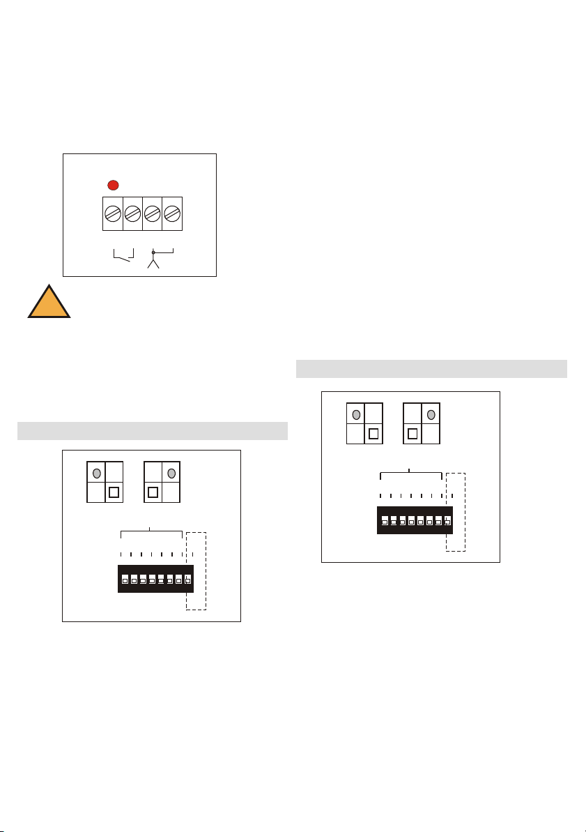
Abb. 22
Zubehöranschlüsse ( Abb. 22)
Klemme 7-8: Anschluß für Taster, L1
blinkt bei Aktivierung
Klemme 9: Antenne
Klemme 10: Schirmung
!Achtung:
Gerät nur Öffnen bei abgeschalteter Netzspannung
6 - PROGRAMMIERUNG
PR
LR
PV
LV
Abb. 23
Dip Schalter 8 : OFF
Dip Schalter 1: ON 10 Sek.
Dip Schalter 2: ON 20 Sek.
Dip Schalter 3: ON 40 Sek.
Dip Schalter 4: ON 1 min.
Dip Schalter 5: ON 2 min
Dip Schalter 6: ON 4 min
Dip Schalter 7: ON 8 min
Dip Schalter 8 : ON
Dip Schalter 1: ON 10 min
Dip Schalter 2: ON 20 min
Dip Schalter 3: ON 40 min
Dip Schalter 4: ON 1 h
Dip Schalter 5: ON 2 h
Dip Schalter 6: ON 4 h
Dip Schalter 7: ON 8 h
Die Zeiten addieren sich je nachdem, welche Dip Schalter auf ON
gesetzt werden.
Beispiel: Für 50 Sek. muß der Dip Schalter 1 und 3 auf ON
gesetzt werden und 2,4,5,6,7,8 in Position OFF.
Pag. 14
7 98 10
Led L1
Leistungssicherung F2: 10A für 2000 W . Für geringere Leistung
kann die Sicherung durch einen niedrigeren Wert ersetzt werden.
54321
ON
6 7 8
OFF
ON
1 2 3 4 5 76 8
54321
ON
6 7 8
OFF
ON
1 2 3 4 5 76 8
54321
ON
6 7 8
OFF
ON
1 2 3 4 5 76 8
54321
ON
6 7 8
OFF
ON
Zeiteinstellung
1 2 3 4 5 76 8
Die Zeitprogrammierung erfolgt durch einen 8 fach Dip Schalter
( Bild 23)
Alle Dip Schalter in Position OFF: Leistungsrelais arbeitet bistabil
( ON/OFF)
Der Dip Schalter 8 ermöglicht die Änderung der Zeitwerte der
einzelnen Dip Schalter.
7 - SPEICHERUNG DER HANDSENDER
Abb. 24
PR
LR
PV
LV
54321
ON
6 7 8
OFF
ON
1 2 3 4 5 76 8
54321
ON
6 7 8
OFF
ON
1 2 3 4 5 76 8
54321
ON
6 7 8
OFF
ON
1 2 3 4 5 76 8
54321
ON
6 7 8
OFF
ON
Zeiteinstellung
1 2 3 4 5 76 8
Speichern am Empfänger
Drücken Sie die Taste PR bis LED rot leuchtet, innerhalb 4 Sek.
drücken Sie die eine Taste (A,B,C,D)
des Handsenders und die rote LED LR erlischt, Relais schalten
kurz.
Bei Handsendern mit Dip Schalter die gewünschte Codierung
einstellen.
8 - LOSCHUNG DES SPEICHERS
Löschen am Empfänger
Drücken Sie die Taste PR bis die rote LED leuchtet, danach
drücken Sie erneut Taste LR und LV gemeinsam bis LED rot und
grün 3 x blinken.
Speicher ist danach komplett gelöscht.
9 - VERWALTUNG DER BENUTZER
Anzeige des Speicherplatzes
Es ist möglich die Speicherplatznummer der zuletzt gespeicherten
Handsendertaste anzuzeigen.
Anzeigeprozedur:
Drücken Sie die Taste PR bis die LED LR rot leuchtet, PR loslassen
und erneut kurz drücken.
Die LED beginnen zu blinken in einer Binärsequenz.
Überschreiben eines eingelernten Handsenders
nur Modell 2641 R433PT
Ein verlorener oder defekter Handsender kann direkt durch
Überschreiben seiner Speicherposition gelöscht und durch einen
neuen Handsender ersetzt werden.
Es ist notwendig die Speicherposition zu kennen.
Drücken Sie die Taste PR bis die LED LR rot leuchtet, dann PR
loslassen.
Drücken Sie die Taste PV mind. 1 Sek.. Innerhalb 2 Sek. beginnen
Sie mit der Eingabe des Speicherplatzes durch PR und PV in 7
Schritten.
Pag. 15
Achtung:
Ein bereits im Speicher befindlicher
Sendercode kann nicht an anderer Stelle
erneut programmiert werden.
Speicher voll
Wenn eine weiterer Handsender eingelernt werden soll und der
Speicher voll ist ( 85/100 Tastencodes ) blinkt die LED LR und LV
drei mal und signalisiert den vollen Speicher. !
LED Blinkfolge 1 2 3 4 5 6 7
LV grün 1 2 4 8 16 32 64
LRrot 0000000
Anzahl der genutzten Speicherplätze
Es ist möglich die im Empfänger belegten Speicherplätze
anzuzeigen.
Anzeigeprozedur:
Drücken Sie Taste des Handsenders kurz, danach drücken PR am
Empfänger für mind. 1 Sek., danach blinken die LED in einer
binären Sequenz. Sie können an Hand der
Tabelle 3 die Speicherposition feststellen.
Programmierbeispiel: PR PV PR PV PR PV PR für Position 42
( siehe Tabelle )
Danach leuchtet die rote LED PR und bestätigt den
Programmiereintritt.
Innerhalb 4 Sek. drücken Sie die Taste des neuen Handsenders
(A,B,C,D)
Die rote LED erlischt und bestätigt die Überschreibung des alten
Handsenders.

La garanzia è di 24 mesi dalla data di fabbricazione apposta all’interno.
Durante tale periodo, se l’apparecchiatura non funziona correttamente, a causa di un
componente difettoso, essa verrà riparata o sostituita a discrezione del fabbricante.
La garanzia non copre l’integrità del contenitore plastico.
La garanzia viene prestata presso la sede del fabbricante.
Guarantee period: 24 months from the productions date placed inside.
In this period if the appliance has any malfunction due to a defective component,it will be
repaired or replaced by the manufacturer.
The warranty doesn't cover the plastic box.
The assistance will be performed at the manufacturer site.
Guarantee
Garanzia
Die Garantie beträgt 24 Monaten vom inneren angezeigten Herstellungsdatum.
Während solcher Periode, wenn das Gerät nicht korrekt wegen eines defekten Bauelements
arbeitet, wird es beseitigt oder nach Hersteller Entscheidung ersetzt.
Die Garantie bedeckt die Integrität des plastischen Gehäuses nicht.
Die Garantie wird beim Sitz des Herstellers geleistet.
Garantie
Garantie
La période de garantie des produits est de 24 mois, à compter de la date de construction.
Durant cette période, si les produits ne fonctionnent pas correctement, cela, à cause d'un
composant défectueux, le produit sera réparé ou remplacé à la discrétion du fabricant.
La garantie ne couvre pas le boîtier en plastique.
Le service après-vente sera fourni par le fabricant.
THE SMART LIVING
Manufactured by Elpro Innotek SpA
Via Piave, 23 - I-31020 S.Pietro di Feletto (TV)
Italy
Tel. +39-0438-450860 - Fax . +39-0438-455628
IS-EC2ERML Rev.1 del 11/12/2007
Note
This manual suits for next models
2
Table of contents
Languages:
Other Erone Motherboard manuals

Erone
Erone 024A Series Technical specifications

Erone
Erone SEL 2641 R433-RM User manual

Erone
Erone SEL2641R433-P4 Technical specifications

Erone
Erone SEP230M2 Series Technical specifications

Erone
Erone SEL2641R433-P7P Technical specifications

Erone
Erone SEL2641R433-P7 Technical specifications

Erone
Erone SEL2641R433-P4P Technical specifications


