ES ANASOL User manual

WALL
HOLES
FOR SCREW FIXING
Differential temperature
LEDs to turn the
pump ON
Differential temperature
button to turn the pump ON
Pump operation mode
control button
Overheating control button
Anti-freeze control button
Pump OFF indication LED
Overheating protection indication led
Pump operation mode
indicator LED
Differential temperature
button to turn the pump OFF
Differential temperature LEDs
to turn the pump OFF
Pump ON
indication LED
Anti-freeze protection
indication LED
5. DISPLAY IDENTIFICATION AND CONTROL BUTTONS
ANASOL
7. INSTRUMENT FIXATION MODE
DIN RAIL
WALL
Wall
DIN rail
Instrument
Spare reinforce screws
(not included)
7.1 DIN mount fixation
7.2 Screw fixation (wall-mounted)
Screws for fixation
(not included)
6. WIRING DIAGRAM
Mere illustrative images
4.4 - Pump operation mode
Press and select the pump operation mode, as follows:
OFF - Manual mode. Pump is always OFF
AUT - Automatic mode. Pump activation following the user settings.
ON - Manual mode. Pump is always ON.
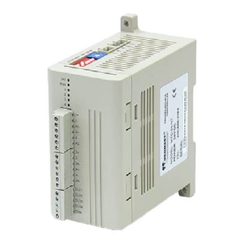
1. DESCRIPTION
ANASOL is a differential thermostat for solar heating that acts through the differential temperature
between sensor S1 (solar collector) and sensor S2 (pool or boiler). Controller for pumped solar heating
systems applications with overheating and anti-freeze functions.
It has anti-freeze function(protection of pipes), prevents water overheating (for pools) also has manual
control of the circulation pump.
2. APPLICATION
Solar heating system for pool or boiler water.
3. TECHNICAL SPECIFICATIONS
- Power supply: 115 or 230 Vac ±15% (50/60 Hz)
-Control temperature: Sensor S1- Metal capsule - Silicone: -50 to 200 °C* / -58 to 392°F**
Sensor S2 - Plastic capsule - PVC: -50 to 105 °C* / -58 to 221°F**
- Load current: 16(8) A / 250Vac 1HP
- Dimensions (W x H x L): 77 x 39 x 97mm
- Differential to turn the pump ON: from 1 to 10 ºC* / 2 to 20°F**
- Differential to turn the pump OFF: from 1 to 10 ºC* / 2 to 20°F**
- Operating temperature: 0 to 45°C* / 32 to 113°F**
- Operation humidity: 10 to 90% RH (without condensation)
* Celsius (Cº) ANASOL model
**Fahrenheit (Fº) ANASOL model
4. SETTINGS
4.1 - Adjustment
To set the controller functions the correspondent key should be press and hold for three seconds until
the led starts to flash. After this first step all functions can be set as desired. The adjustment validation
only will be effective after the led stop flashing (three seconds after the key idleness).
4.1.1 - Differential to turn the pump ON
Press to set this function. The led shows the temperature differential to activate the pump.
4.1.2 - Differential to turn the pump OFF
Press to set this function. The led shows the temperature differential to deactivate the pump.
Example: T ON = 8°C
T OFF = 2°C
When the difference between sensor 1 and sensor 2 goes higher than 8ºC it will activate the pump. The
pump will only shutdown when the differential temperature between both sensors reach less than 2ºC
degrees.
4.2 - Protection against overheating
Allows to adjust the temperature to protect against overheating of the sensors S1 and S2, shutting down
the water circulation pump if the temperature reaches the selected values.
- Protection against overheating in Sensor S1: The pump is switched off to prevent the
superheated water circulates through the pipes and damage them (if PVC pipes are used).
- Protection against overheating in Sensor S2: The pump is switched off to keep the thermal
comfort of reservoir water, mainly used in swimming pools.
The hysteresis of this function has a fixed value of C * 2 / 4 F ** that will reactivate the water pump when
the temperature decreases to the selected value minus the hysteresis. To disable this function select
“OFF” through .
DIFFERENTIAL
FOR SOLAR HEATING
THERMOSTAT
4.5 - Signaling
The PUMP ON led ON indicates that the “NO” output is activated (pump ON).
The PUMP OFF led ON indicates that the “NC” output is activated (pump OFF).
Flashing PUMP ON and PUMP OFF leds indicates the following:
-Some of the temperature sensors are disconnected
-Temperature out of control range
The T ON and T OFF leds flashing indicates the following:
-The temperature setting is higher than .
4.3 - Anti-freeze protection
If the temperature in the sensor 1 reaches lower values than set by the user, the water pump will activate
to prevent water freezing in the pipes. The anti-freeze function has 4ºC / 8 ºF as preset value to
deactivate the water pump when the temperature on sensor 1 goes over the freeze protection value,
plus the differential to deactivate the pump (hysteresis). To disable this function select “OFF” through
When activated by this function the water pump will keep 3 minutes (minimum) activated, regardless of
the sensor 1 temperature.
* **
. .
1
2
Mere illustrative images
Ver.02
The LED always shows the configuration of sensor S2. To see the configuration of the sensor S1,
briefly press the button, the LED will blink quickly in the corresponding value.
Sensor 2 indication
To adjust the overheating protection in the sensor S2
press for 3 seconds (LED blinking slowly).
Sensor 1 indication
To adjust the overheating protection in the sensor S1
press for 10 seconds (Led blinking quickly).
Power
supply
Pump
Load
supply
0
5 - 6 115V
5 - 7 230V
115V
230V
Sensor S1- Metal capsule - Silicone
Panels or solar collector
Sensor S2-
Reservoir/Pool
Plastic capsule - PVC
NEWANASOL02-04T-12219

IMPORTANT
As chapters of IEC 60364 norm:
1: Install protectors against overloads on power supply.
2: Sensor cables and computer signs can be together, however not in the same conduction; where there
power supply and load drive.
3: Install suppresors (RC filters) in parallel to loads to increase the relays function.
Wiring diagram of suppresor in contactors Wiring diagram of suppresor linking in loads
direct drive
Load For direct activation the maximum
specified current should be taken
into consideration.
A1
A2
A1 and A2 are the
contactor coil.
Suppresor
Suppresor
ENVIRONMENTAL INFORMATION
Package:
The packages material are 100% recyclable. Just dispose it through specialized
recyclers.
Products:
The electro components of Full Gauge controllers can be recycled or reused if it is
disassembled for specialized companies.
Disposal:
Do not burn or throw in domestic garbage the controllers which have reached the end-of-
life. Observe the respectively law in your region concerning the environmental
responsible manner of dispose its devices. In case of any doubts, contact Full Gauge
controls for assistance.
