Escea KSE User manual

630111_5 Kitset Wall Unit Installation Manual
Kitset Enclosure –KSE
(Kitset Wall Unit - KWU)
Suitable for EF5000 or EW5000
Installation Manual
Important:
The Kit shall be installed in accordance with:
•This installation instruction booklet
•Municipal building codes
•All relevant statutory regulations.
•Must be installed by a qualified person
For contact details of your local escea distributor or dealer please contact one of the following:
Manufactured by:
Escea Ltd
PO Box 5277
Dunedin
New Zealand
Contact Details (NZ):
Web: www.escea.co.nz
Email: [email protected].nz
Ph: +64 3 479 0302
F: +64 3 479 0301
Contact Details (AU):
Web: www.escea.com.au
Email: [email protected]m.au
Ph (East Coast): +61 3 8787 3567
Ph (West Coast): +61 8 9373 7000
Contact Details (US):
Web: www.escea.net
Email: info@escea.net
Ph: 866 615 3096
F: 770 412 8403

630111_5 Kitset Wall Unit Installation Manual
Finished Dimensions:
Note: Third angle projection

630111_5 Kitset Wall Unit Installation Manual
Note: You will need a 13mm (1/2”) Spanner and/or socket and ratchet handle.
Kitset Contents:
It is important to check that the contents of your KSE (KWU) Flatpack is complete
before you start the assembly process.
Your Flatpack should include the following components:
56 x M8x20mm (5/16 x 13/16”)
Hex Bolt
Part #303053
1 x Top Section
Part #700029
1 x Middle Section
Part #700030
1 x Bottom Section
Part #700031
(corner gussets attached for
fixing to ground)
2 x 583mm (22 15/16”) Vertical
Part # 120008
4 x 1098mm (43 7/32”) Vertical
Part # 120003
1 x 1698mm (66 55/64”) Horizontal
Part # 120004
4 x Triangle Gusset
Part #100402
9 x Corner Bracket
Part #100401

630111_5 Kitset Wall Unit Installation Manual
Assembly
When tightening the bolts to the frame, make sure the parts are lined up correctly.
This will ensure that you do not cross-thread the bolt inside the riv-nut. On initial
assembly, tighten bolts lightly, tighten properly once the KSE (KWU) frame is
complete.
Step 1 –Section One
Parts needed for step 1 & 2
Item
Qty
Bottom Section
1
Corner Bracket
4
1098mm (43 7/32”) Vertical
4
M8x20mm (5/16 x 13/16”) Hex Bolt
16
Step 2
Corner Gusset
Insert 2 Hex Bolts for each
corner bracket and screw
to the bottom section.
Insert 2 Hex Bolts for each corner bracket and
screw to the 1098mm (43 7/32”) vertical
supports.

630111_5 Kitset Wall Unit Installation Manual
Step 3
Once the top section is in place it can be attached with the hex bolts to the 1098mm
(43 7/32”) vertical supports. Section One is now complete.
To assemble the top section, repeat
step one then slide it between the
1098mm (43 7/32”) vertical
supports.

630111_5 Kitset Wall Unit Installation Manual
Step 4 –Section Two
The next step is to assemble the internal
section of the KSE (KWU). This section
will support the EF5000 Outdoor
Fireplace.
Attach the four triangle gussets to the Horizontal, Vertical and Middle sections as
shown. Section Two is now complete.
Item
Qty.
Triangle Gusset
4
1698mm (66 55/64”) Horizontal
1
583mm (22 15/16”) Vertical
2
M8x20mm (5/16 x 13/16”) Hex Bolt
20
Middle Section
1

630111_5 Kitset Wall Unit Installation Manual
Step 5
Attach Section Two to Section One.
Ensure correct orientation as shown.
Ensure central short upright bracket is fastened to Section Two.
Item
Qty.
Section One
1
Section Two
1
M8x20mm (5/16 x 13/16”) Hex Bolt
4

630111_5 Kitset Wall Unit Installation Manual
Step 6 - Fixing to the Ground
Attached to the bottom section of the Kitset Enclosure (Kitset Wall Unit) are 4 corner
gussets. Bolts or Dyna-bolts must be inserted into the gussets to secure the KSE
(KWU) to the ground.
Important: Ensure that appropriate vertical seismic restraints are readily available to
match the building code of your area.
Step 7 - Adding Your Own Unique Finish
Now that your Kitset Enclosure (Kitset Wall Unit) is complete, you can now add your
own choice of cladding to finish it off. Different applications and installations require
unique claddings, hence Escea have made the Kitset Enclosure (Kitset Wall Unit) to
be as flexible as possible. Below are some guidelines on how the cladding should be
completed.
The unit was designed with 300mm (11 13/16”) x
300mm (11 13/16”) tiles in mind, but any finish from
stone veneer, rough-cast plaster, timber or
anything else that you can think of, could be used
to good effect.
When planning your finish, make allowance for the
fact that the Fire Fascia will cover part of that outer
layer, and must sit in front of the cladding, not
flush with it (see diagram at left).It may be a
good idea to mock-up the installation in order to
get it right.
Inserted into solid structure
WALL LINING
NON COMBUSTIBLE
STONE VENEER
DISTANCE BETWEEN
TOP OF FASCIAAND
BOTTOM OF
VENEER/LINTEL
MUST BEAT LEAST
40mm [1 ” ]½
AIR GAP BETWEEN
BOTTOM OF FASCIA
AND TOP OF VENEER
MUST BEAT LEAST
40mm [1 ”]½
EF5000 ONLY

630111_5 Kitset Wall Unit Installation Manual
The size of the Kitset Enclosure (Kitset Wall Unit) has been designed to fit in with
standard 2400mm [8’] x 1200mm [4’] sheets. If the Kitset Enclosure (Kitset Wall Unit)
is to be installed up against a wall or similar structure, only two full sheets are
required. If it is to be set up as a standalone unit, a third sheet may be required.
A Guide to Sheet Cutting
If you are using fibre cement board, plywood (for EF5000 only) or similar full-sized
sheets as the initial cladding, they can be cut quite economically to suit the Kitset
Enclosure (Kitset Wall Unit). The first sheet should be cut into two pieces as
illustrated below:
Note: Do not use plywood as a cladding option for the EW5000, refer to the EW5000
installation manual for more information.
The second sheet should be cut into three pieces as illustrated below:
630111_5 Kitset Wall Unit Installation Manual
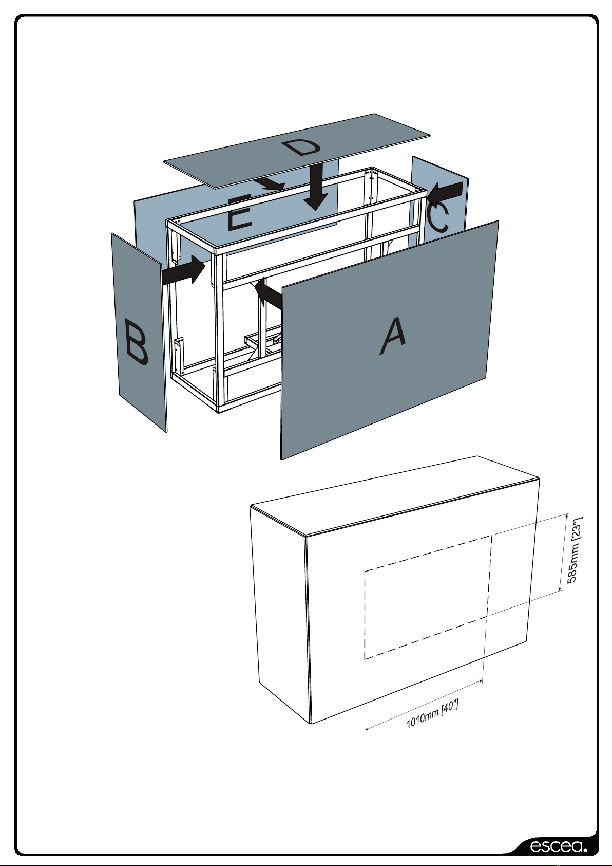
These panels can then be attached, using suitable adhesive or mechanical
fastenings, to the assembled unit as illustrated below:
Note that panel ‘E’ is optional,
particularly if the rear of the
Kitset Enclosure (Kitset Wall
Unit) is backing against a wall
or similar structure.
If it is desired that the Kitset
Enclosure (Kitset Wall Unit) is
to be fully enclosed, then a
third sheet will be required in
order to cut another panel ‘E’,
or another panel ‘A’.
Escea recommends that the
hole in the front panel ‘A’ be
marked out and cut after it
is fixed to the unit to ensure
it is in the correct place. Check that the fireplace fits before finishing the veneer.
Install the EF5000 Outdoor Fireplace according to the installation instructions that
came with it.

630111_5 Kitset Wall Unit Installation Manual
EW5000 ONLY:
Step 8: Installing the EW5000
Insert the firebox into the kitset enclosure as
shown in the picture.
Note: The final position of the firebox will be
dependent on the type of material you have
chosen for cladding.
Be careful to position the firebox so the bottom
lines up with your wall. If the wall lines up with
the top or sides, the fascia will not fit on. There
are 4 holes in the bottom of the fire for securing
the fire into a cavity. These holes do NOT line up with the kitset enclosure, and you will need
to drill 2 additional holes, in the base of the firebox, for securing the fire. To stop any embers
from falling into the cavity of the kitset enclosure, the 4 original holes in the bottom of the fire
must be “blanked off” with the supplied nuts and bolts.
There are an additional 2 holes in the bottom corners of the rear panel. If these are not
utilized as fixing holes, they should be ‘blanked off’ with the supplied nut and bolts.
Depending on material choice some heat may be conducted through the surrounding cavity
and consequently no combustible materials should be near or come into contact with these
hot surfaces. This is completely dependent on the chosen material and design of installation.
The user should satisfy themselves that the installation is fit for purpose and complies with
all local and national codes.
Step 9:
First you must position the fire in the kitset enclosure so that the bottom of the fire lines up
with the outside of the cladding you have chosen. See pictures for example. Notice that the
bottom does not line up with the kitset enclosure. The bottom must line up with whatever
cladding is being used for the enclosure. In this case a piece of stone veneer has been used.
In the example shown the cladding is 35 mm thick. Therefore, the bottom edge of the fire
must be sitting 35 mm from the front of the kitset enclosure.
Important: Once the fire has been appropriately positioned within the kitset enclosure, vertical
seismic restraints must be added.
630111_5 Kitset Wall Unit Installation Manual
Step 10:
Once the fire is sitting in the correct position, mark and drill two 6mm clearance holes for the
self-drilling screws in the bottom of the fire. Make sure the holes are located directly above
the centre of the 25x50 mm box section. Do NOT drill holes into the box section. To make
sure you do NOT drill into the box section, the fire should be moved slightly whilst drilling the
holes.
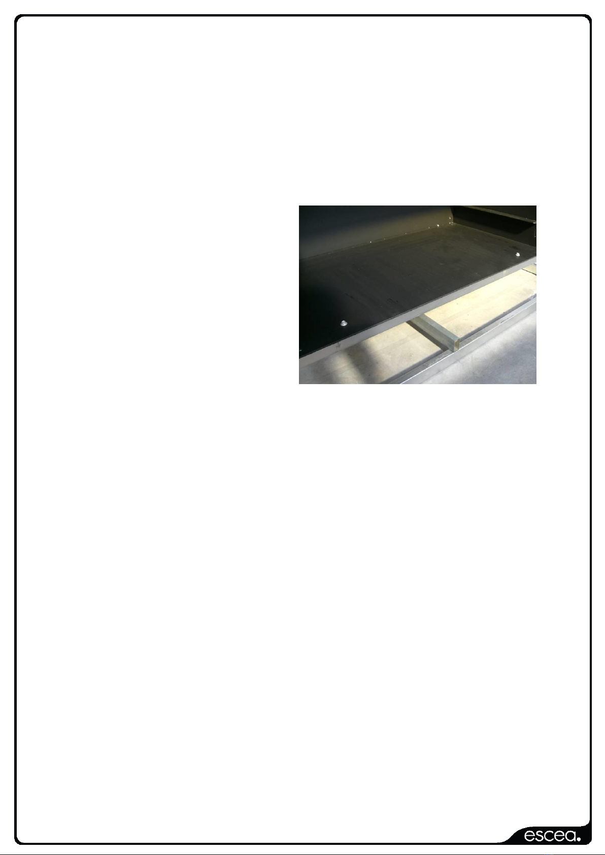
Once the clearance holes have been drilled
the fire can be placed into its final position.
Before securing the fire, you must make
sure it is level. Use pieces of non-
combustible material to sit firmly under the
corners of the fire to make it level.
Use the supplied TEK-screws for securing
the fire to the middle section as shown in
the picture. Make sure not to over tighten
the bolts, and use a spanner for tightening
rather than an electrical drill.
Note: when determining the position of the 6 mm holes, make sure the screws will not be in
the way of the ash-pan. If the screws are positioned between 50 and 150 mm from the inside
walls of the fire, they will clear the ash pan.
Your EW5000 outdoor cooking fire is now installed in your Kitset Enclosure. Make
sure all of the guidelines of both the installation manual for the EW5000 outdoor
cooking fire and the kitset enclosure are followed.
Popular Indoor Furnishing manuals by other brands

The Land of Nod
The Land of Nod Monarch Full Bed Assembly instructions

Studio Designs
Studio Designs HOME LINTEL 72030 Assembly instructions

GRAVITY
GRAVITY GFDJT01 Assembly instructions

PAIDI
PAIDI 219 9701 instructions

tropitone
tropitone Mobilis Assembly instructions

Pioneer Woman
Pioneer Woman PWS336158813027 manual

Argos
Argos New Sywell 411/1524 Assembly instructions

Serta
Serta B565QDC Assembly instructions

DIVERSIFIED WOODCRAFTS
DIVERSIFIED WOODCRAFTS AMT-6030S Series Assembly instructions

Next
Next FINSBURY CABIN STATION 683543 Assembly instructions

Home Decorators Collection
Home Decorators Collection Aberwood DP18020-P Use and care guide

sweeek.
sweeek. OSKAR ISOFABEDCVV manual


