ESi Ergo VICTORY 2VT-C36-30 Series User manual
ASSEMBLY AND OPERATION
VICTORY Model 2VT-C36-24-___
Model 2VT-C36-30-___
Model 2VT-C48-24-___
Model 2VT-C48-30-___
___ = SLV, BLK or WHT
2 LEG ELECTRIC TABLE BASE
2VT Rev A 1/17
2
VICTORY 2 LEG ELECTRIC TABLE BASE PARTS AND TOOLS
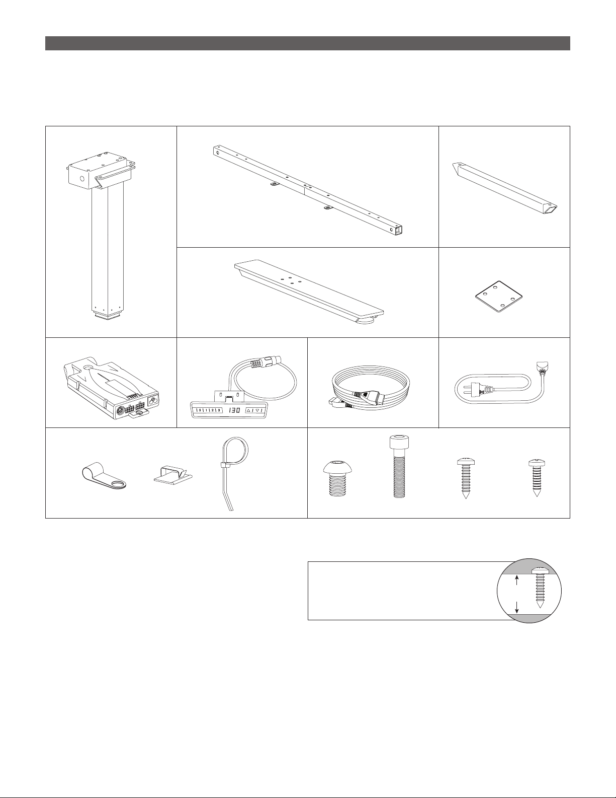
PLEASE REVIEW these instructions before beginning the assembly procedures. Check that all the parts shown
below were provided with your order. Contact your supplier if any materials are missing. Do not discard the
packaging until satised that the product operates to your satisfaction.
PARTS PROVIDED
Cross Channels (2)Legs with Motor (2)
Digital Keypad (1)Control Unit (1) Power Cable (1)Motor Cables (2)
Top Supports (2)
CAUTION: Hand-tighten screws only. Do not use
power tools.
Cable Clamps and Ties Fasteners
Feet (2) Foot Plates (2)
M6x35 (8)
M8x12 (12)
(6)(3)
(6)
ST 4.8x19 (19) ST 2.9x19 (2)
ADDITIONAL TOOLS REQUIRED
• 5mm Allen key
• Phillips screwdriver CAUTION: Always check that screws
used to attach components to the
work surface are not too long for the
thickness of the surface.
Work
Surface
3
ASSEMBLY VICTORY 2 LEG ELECTRIC TABLE BASE
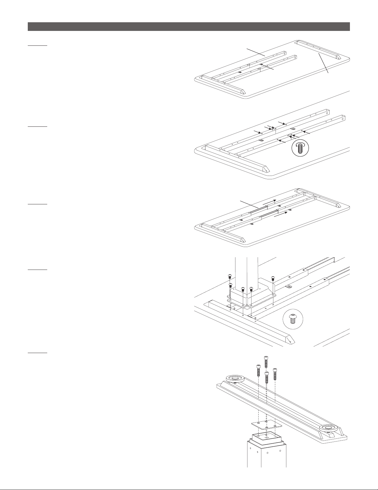
STEP 1
With the table top facing down on a soft, clean
surface, arrange the cross channels and top
supports as shown.
• Positioning does not need to be exact at this time.
• Mounting tabs on the cross channels face inward,
toward each other.
• Holes on the top supports are offset to the rear.
STEP 2
Use an 5mm Allen key to loosen the M10 set screws
on the cross channels (two on each side of center).
STEP 3
Adjust the cross channels to their approximate nal
lengths, as shown.
• Center the inner piece in each cross channel.
STEP 4
Attach the side legs to the cross channels and top
supports with six M8x12 screws per leg.
• Use a 5mm Allen key.
• Two screws attach to each cross channel and
two screws attach to the top supports.
STEP 5
Attach a foot plate and foot to each of the side
legs with the M6x35 screws.
• First, place the foot plate onto the leg with the
smooth side up.
• Position the foot over the foot plate, as shown.
The short side of each foot should face the rear.
• Screw the foot securely in position using a 5mm
Allen key.
Loosen
Set Screws
Top
Support
Cross Channel
Mounting Tab
Center
Inner Piece
M8x12
Foot Plate
Side
Legs
M6x35
Rear
Front
4
VICTORY 2 LEG ELECTRIC TABLE BASE ASSEMBLY
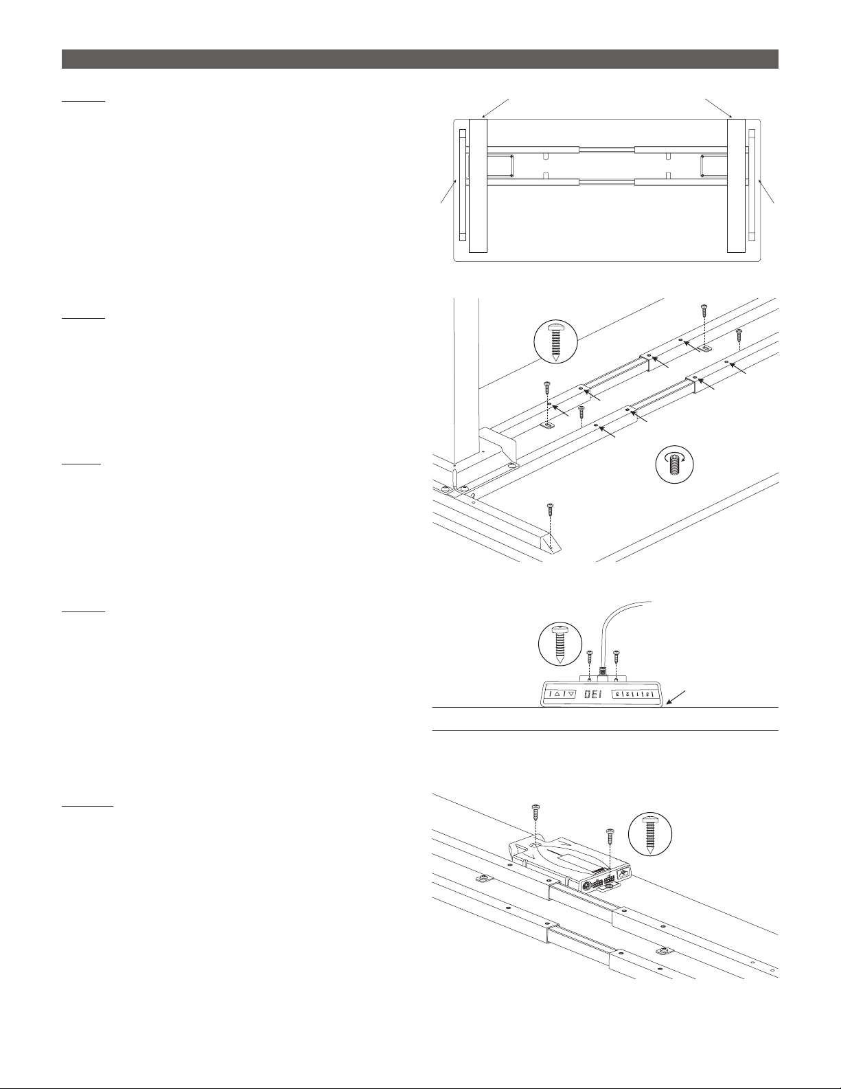
STEP 6
Adjust the position of the frame before screwing it
to the table.
• The top supports on each side should be
approximately 1" (25mm) from the ends of the
table.
• The rear of the feet should align with the rear
of the table.
STEP 7
Once in their nal position, attach the top supports
and cross channels to the table.
• Use ST4.8x19 screws (8 total required).
• Attach the screws through the mounting tabs on
the cross channels and through the holes at the
ends of the two top supports.
STEP8
Tighten the M10 set screws in the cross channels
(8 total). Use the 5mm Allen key to hand tighten.
STEP 9
Attach the digital keypad using the two ST2.9x19
screws.
• Position the digital keypad on the left or right side
of the table, according to user preference.
• Align the top of the keypad with the edge of the
table so that the controls will be easily accessible.
STEP 10
Attach the control unit using two ST4.8x19 screws.
• Position the control unit near the back of the
table, on the same side as the digital keypad.
• Be sure the cable from the keypad can reach
the control unit, and the motor cables can
extend from the control unit to both motors.
ST2.9x19
Digital Keypad
Aligned with
Edge of Table
Align Rear of Feet with Rear of Table
1" 1"
Tighten
Set Screws
ST4.8x19
Control
Unit ST4.8x19
5
ASSEMBLY VICTORY 2 LEG ELECTRIC TABLE BASE
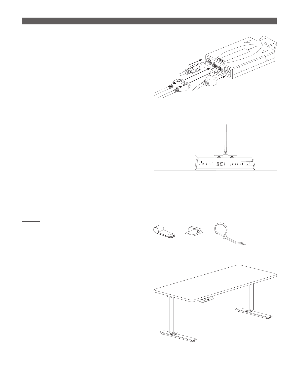
STEP 11
Make connections to the control unit and motors.
• Connect the cable from the digital keypad.
• Connect the motor cables to the control unit and
to each of the motors on the table legs.
• Connect the power cord to the control unit.
• Plug the power cord into an AC outlet.
CAUTION: Do not operate the table until after “zero
setting” the system. See following step.
STEP 12
“Zero set” the system before testing operation.
• Press DOWN tto lower the legs to their lowest
position. (Note that with the table upside-down,
the DOWN arrow faces up).
• Press DOWN t again for about ve seconds.
The legs will move further down slightly to their
absolute lowest position. Release the DOWN t
button.
• Press the UP sand DOWN t buttons to test
operation. End your test with the legs lowered
and unplug the power cord.
• If there are problems with operation, check that
all cable and cord connections are secure. If
problems continue, call ESI Customer Service.
STEP 13
Use the cable clamps and ties to secure the cables
in position.
• Cables must not interfere with table operation.
• Cables must not interfere with the user.
STEP 14
With the assistance of a helper, turn the table
upright and place it in its nal position.
IMPORTANT: There must be 1" (25mm) of clearance
on all sides of the work surface (and other moving
parts) to ensure free, unobstructed movement.
• Adjust the leveling glides on the feet to level the
work surface, if necessary.
• Plug the power cord into an AC outlet.
• See the following pages for operating
procedures.
Cable Management
Keypad
Cable
Motor
Cables Power
Cable
DOWN ▼Button

6
VICTORY 2 LEG ELECTRIC TABLE BASE OPERATION
GENERAL OPERATION
Move the table up or down by pressing UP sor DOWN tuntil
the work surface reaches the desired height.
The table will continue to move up or down until you release the
button or until the maximum or minimum height is reached.
MINIMUM AND MAXIMUM STOP POSITION
This feature can be used to limit the range of table travel to
prevent the work surface from hitting items below or above it.
• The minimum stop position must be in the lower half of the
movement range, and the maximum stop position must be in
the upper half.
• Minimum and maximum stop positions must be set separately.
To set a stop position:
• Move the work surface to the desired minimum or maximum
height.
• Press and hold both the UP sand DOWN tbuttons for 10 to 15
seconds. The control unit will click twice when the stop position
has been stored.
To erase a stop position:
• Move the work surface to the stop position to be erased.
• Press and hold both the UP sand DOWN tbuttons for 10 to 15
seconds. The control unit will click once when the stop position
has been erased.
SAVING A TABLE POSITION
The three memory buttons can be used to save specic positions
of the work surface. To set a specic position:
• Adjust the work surface to the position you want to save. (The
display on the control pad shows the work surface height.)
• Press the Setting button S. The display will read S––.
• Press the desired Memory button, 1, 2or 3. Let’s say you
pressed 1. The display will read S1.
• The work surface position is now saved. The control unit will
click twice after about two seconds and the display will show
the work surface height.
Setting
Button
Memory
Buttons
Table
Height
DOWN
Button
UP
Button
CAUTION: The “zero setting” procedure
must be completed before operating the
table. See Step 12 on page 5.
You can set a minimum stop, a
maximum stop, or both a minimum
and maximum stop.
Minimum and maximum stops can
serve the same function as memory
stops. For example, minimum stop
could be the user’s standard sitting
position and maximum stop could
be the user’s standard standing
position.
Default stop position for the three
memory buttons is the lowest height
of the work surface.
Table movement stops when you
release the UP
s
or DOWN
t
button.

7
OPERATION VICTORY 2 LEG ELECTRIC TABLE BASE
MOVING THE WORK SURFACE TO A SAVED POSITION
Use this function to move the work surface to one of the saved
positions.
• Press and hold the desired memory button, 1, 2or 3. The work
surface will move to the saved position and then stop.
• Release the memory button. The work surface will move to
the saved position and then stop. The display shows the work
surface height.
CHANGING THE HEIGHT DISPLAY UNITS
This function allows you to change the display units from
centimeters to inches or the other way around.
• Press and hold memory buttons 1and 2and the UP sbutton.
• Release the three buttons after about ve seconds. The display
will show Sand a number — for example, S5.
• Press UP suntil the display reads S5.
• Then press the Setting button S. If the display was set to
centimeters, it will now be set to inches; or vice-versa.
RESET THE CONTROL UNIT TO FACTORY SETTINGS
To reset the control unit to factory settings:
• Press and hold memory buttons 1and 2and the UP sbutton.
• Release the three buttons after about ve seconds. The display
will show Sand a number — for example, S5.
• Press UP suntil the display reads S0.
• Then press the Setting button S. The control unit is now reset to
factory settings.
CAUTION: After resetting the control unit, the “zero setting”
procedure must once again be completed before operating the
table. See Step 12 on page 5.
If you release the memory button
before the saved position is reached,
table movement will stop.
If one or more motors are changed
in a system, the control unit must
be reset to factory settings and
the system must be “zero set” as
described earlier.

800.833.3746 esiergo.com
© 2017 ESI Ergonomic Solutions. All rights reserved. 2VT Rev A 1/17
This manual suits for next models
3
Table of contents
Popular Indoor Furnishing manuals by other brands

Extron electronics
Extron electronics Wall Plates WPB 170 Specifications

DITALIA
DITALIA R-609 Assembly manual

Sareer
Sareer Sareer 3' Underbed Assembly instruction

Sauder
Sauder Summer Home Pantry 401867 Instruction booklet

Union Home
Union Home Oslo Queen Bed BDM00022 quick start guide

Safavieh Furniture
Safavieh Furniture Janet FOX2005 Assembly


Alera
Alera ALE-TH41FG10G Assembly & operating instructions

Whittier Wood
Whittier Wood 1242DUETa Assembly instructions

VIPACK
VIPACK CHHS9014 Assembly instructions

Manhattan Comfort
Manhattan Comfort CITY 1.2 Assembly instructions

Flash Furniture
Flash Furniture GM-UB19-BZ-GG Assembly instructions

Sleepmasters
Sleepmasters LUCETTA BEDSTEAD Assembly instructions