ESP Varimax 20 ASHP User manual

1 of 41
V 1.0
www.esavep.com PASRW060-D-BP
ESP VARIMAX 20 ASHP
Installation and
Operation Manual

2 of 41
V 1.0
www.esavep.com PASRW060-D-BP
WARNING!
READ THIS BEFORE
INSTALLING
THE UNIT.
The installation of all un-vented water heating systems above 15 litres
MUST comply with local area Building Regulations. It is a legal
requirement that the local Building Control Officer be notified of any
proposed installation.
UK regulations require an appropriately sized expansion vessel
(internal or external) to be incorporated, safety devices to prevent the
stored water exceeding 100°C, and pipe work to convey discharged hot
water safely away from the safety devices.
Furthermore, the installation must be carried out by an engineer who
has successfully completed a recognised course in the installation of
un-vented heating systems such as CITB. Failure to fit the unit
correctly and in accordance with regulations may affect its safety,
efficiency and WILL invalidate any guarantee.
THE UNIT MUST BE INSTALLED, COMMISSIONED AND MAINTAINED BY A
COMPETENT INSTALLER IN ACCORDANCE WITH BUILDING REGULATION
G3 (ENGLAND AND WALES), TECHNICAL STANDARD P3 (SCOTLAND) OR
BUILDING REGULATION P5 (NORTHERN IRELAND) AND THE WATER
FITTING REGULATIONS (ENGLAND AND WALES) OR WATER BYELAWS
(SCOTLAND). FOLLOWING INSTALLATION AND COMMISSIONING, THE
OPERATION OF THE UNIT SHOULD BE EXPLAINED TO THE USER AND
THESE INSTRUCTIONS LEFT WITH THEM FOR FUTURE REFERENCE.

3 of 41
V 1.0
www.esavep.com PASRW060-D-BP
Contents:
1.0 Preface
1.1 Features of the Varimax 20 ASHP
2.0 Safety Precautions
3.0 Varimax 20 Specifications
3.1 Appearance
3.2 Dimensions
4.0 Choosing the right heat pump
4.1 Heat Load Calculation
4.2 Varimax 20 Output Statistics
4.3 Emitter systems
5.0 Installation
5.1 Where to use and Where to Site the unit
5.2 Location of the Unit
5.3 Transporting the Unit
5.4 Plumbing Considerations
6.0 Hydraulic Connection
6.1 Expansion vessels
6.2 Flow Switch
6.3 Flexi Hoses
6.4 Automatic bleed valves
6.5 Transit Bung
6.6 In-Line Filter
6.7 Flow Setter
6.8 TRVs
6.9 Distribution Water Pump
6.10 Glycol
7.0 Electrical Connection
7.1 Warning Notes
7.2 Before You Start
7.3 MCB
7.4 Isolation Switch
7.5 Cable Routing

4 of 41
V 1.0
www.esavep.com PASRW060-D-BP
7.6 Wiring-in The Unit
8.0 Unit Specifications
9.0 Commissioning
9.1 Pre-Start Checks
9.2 Switching on the Unit
10.0 UNIT CONTROLLER
10.1 main Interface
10.2 Basic Operation
10.3 Start-UP and Shut-Down
10.4 Setting the Target Temperature
10.5 Using the Premium User Interface
10.6 Setting the Time
10.7 Setting the Timers
10.8 Cancelling the Timers
10.9 Checking the Status of the ASHP
10.10 Locking the Display
10.11 Fault Displays
11.0 Maintenance
11.1 Essential Checks
11.2 Advisory Checks
12.0 Trouble Shooting
12.1 Error Codes
12.2 Simple Faultfinding
13.0 Wiring Diagram
14.0 Guarantee
14.1 Guarantee Terms
15.0 Environmental Information
16.0 Weather Compensation
17.0 Performance
18.0 Parameter List

5 of 41
V 1.0
www.esavep.com PASRW060-D-BP
1.0 Preface:
This manual includes important information about the installation and
maintenance of the ESP Varimax 20 inverter driven air source heat pump
(ASHP) unit. Please read this manual carefully before installing or carrying
out maintenance works on the unit. Please note that, failure to observe the
provisions in this manual will invalidate any warranty on the unit and may
lead to loss and/or damage to people and/or property for which ESP will not
be liable. All ESP ASHPs are covered by the warranty contained in the ESP
Terms and conditions of Business a copy of which will have been provided to
you prior to your purchase.
The Varimax 20 must only be installed by suitably qualified personnel.
The Varimax 20 air source water heat pump is a high efficiency, energy
saving and environmentally friendly unit that should be used primarily for
space heating. It can work with any kind of heat emitter scheme such as
under floor heating, the ESP Thermovec fan coil unit or traditional radiators.
The Varimax 20 can also be used to generate domestic hot water (DHW) for
sanitary purpose although ESP strongly recommend that space heating is
achieved with an ASHP and the DHW requirement be met by an ESP Ecocent
unit. PLEASE NOTE that operating conditions, such as ambient air
temperature, required water flow temperatures, target room temperatures
and humidity will influence the operating efficiency of the unit.
1.1 Features of the Varimax 20 ASHP:
1. Advanced controls
All user set parameters can be controlled via A PC based
controller that can control several units simultaneously.
2. Appearance
The Varimax 20 is designed to be attractive and discrete.
3. Compact design
Our Varimax 20 units have a built-in water pump and are
stand-alone units (monobloc) to make installation simple and quick.
4. Quiet running

6 of 41
V 1.0
www.esavep.com PASRW060-D-BP
High quality and efficient compressors, fans, water pumps and sound
insulation combine to ensure a very low running noise of 59 dBa.
5. Efficiency
The Varimax20 unit is equipped with a highly efficient heat exchanger
to deliver exceptional efficiency.
6. Wide operating temperature capability
The Varimax I unit is designed to work effectively and efficiently
down to -10°C ambient air temperature.
2.0 SAFETY PRECAUTIONS
It is important to take the following precautions when planning your
installation, installing and operating the Varimax 20: Failure to observe these
points could lead to loss or damage to property and/or injury/death of
installers/operators and will invalidate the warranty.
The unit must only be installed, moved and/or repaired by a suitably
qualified and experienced engineer. If you are in doubt about who is
qualified to carry out such works on the Varimax 20 unit, please call
ESP.
The Unit MUST be properly earthed.
Do not put fingers or other objects into the grill covering the fan and
make sure that children do not play close to the unit. The grills are
there for a good reason.
If you hear abnormal noises, or smell strange odours, coming from
the unit, switch it off immediately and call your installer or ESP.
Do NOT install the unit close to any gas fired appliance, heater or fire.
Ensure that the base on which the unit is secured is both large and
strong enough to take the weight of the unit comfortably and will not
subside. The base should also be at least 150mm above the
surrounding ground level and you should check the base periodically
to ensure that there is no subsidence of the base or the immediate
surrounds. In areas prone to flooding, care should be taken to

7 of 41
V 1.0
www.esavep.com PASRW060-D-BP
ensure that the unit is elevated to avoid flood damage.
Ensure that you use a suitably rated circuit breaker. If in doubt, have
your electrician call ESP Technical Support.
Switch off the power before carrying out any cleaning and/or
maintenance of the unit.
3.0 VARIMAX 20 SPECIFICATIONS
3.1 APPEARANCE
The Varimax 20 is designed to be stylish but
unobtrusive. It can be installed with or
without the front louvre covering the fans.
The cabinet is weather resistant and designed
to look good throughout the life of the unit.
W
i
r
e
c
o
n
t
r
o
l
l
e
r

8 of 41
V 1.0
www.esavep.com PASRW060-D-BP
3.2 Dimensions
4.0 Choosing the right heat pump
4.1 Heat Load Calculation
Based on the local climatic conditions, construction features and insulation
levels, your system designer will calculate the heat load of your building and,
therefore, the appropriate unit size for your building. ESP can provide a
heat load calculation that conforms to MIS 3005. For new builds, meeting
the requirements of current building regulations for insulation (or better)
will help ensure that the heat load of the dwelling is kept to a minimum. For
existing buildings, insulation should be improved as much as possible to
minimise the heat load.
4.2 Varimax Output Statistics
The Varimax 20 has been tested according to BS EN 14511, EN 14825 and
12102. Additionally it has been tested in accordance with EU Directive
813/2013 to prove the ErP rating. The choice of ASHP for your purposes
should be based upon the output proven by these tests and the conditions
stated in MIS 3005. Performance graphs are included in section 18.
Make sure that your supplier/installer is familiar with the most recent
requirements of MIS 3005.
1475
1000
Unit viewed from the
top

9 of 41
V 1.0
www.esavep.com PASRW060-D-BP
The Varimax 20 unit is MCS Certified and, if you wish to take advantage of
certain funding that may be available, your unit MUST BE INSTALLED BY AN
MCS ACCREDITED INSTALLER –please consult your supplier or ESP should
you require further clarification.
4.3 Emitter system.
The Heat pump must be matched to a suitable emitter system. The
Microgeneration Certification Scheme website offers guidance on pipe
spacing for UFH systems together with sizing consideration for fan coil units
such as the ESP Thermovec and traditional wet radiators can be found.
Please note that, in the case of an UFH system, the floor coverings must be
chosen very carefully to ensure that the heat is not ‘trapped’ in the floor by
laying the wrong floor covering for the individual room heat load. Again,
guidance is available from the MCS website.
5.0 Installation
5.1 Where to use and Where to Site the unit
The Varimax 20 can be used for domestic or commercial premises and
consideration should be given to the following when choosing an installation
site:
The unit must be installed in an outdoor location on a solid base
that can carry the weight of the unit. This can be on the ground, a
roof or balcony. If it is to be installed on a roof or balcony, a steel
frame must be used. Please contact ESP for further details.
The site must be well ventilated but NOT windy.
The site should be away from sources of high heat.
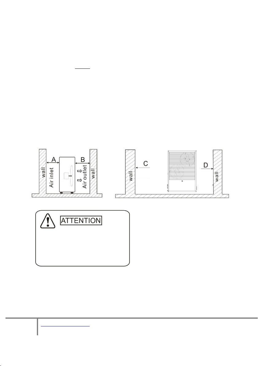
The unit must be sited away from any obstacles to the rear and
sides. There must be enough space around the unit for plumbing and
maintenance works as detailed in the diagram below. Care should
also be given to ensure that any overhead obstacles cannot create a
re-circulating air flow (where air exhausted from the ASHP is sucked
back in).
Further information is included in the section below entitled

10 of 41
V 1.0
www.esavep.com PASRW060-D-BP
“Location of Unit”.
The unit generates condensate and this should be piped away
from the unit and into a suitable drain to prevent ice forming on the
area around the unit. This also applies to the water resulting from a
defrost cycle.
The unit MUST be firmly fixed to a secure base using the rubber
anti-vibration feet using suitable fixings. Failure to secure the unit
properly using the rubber feet will mean that it will fail MCS
Certification and cannot be registered on the MCS database.
To allow precipitation to run off the unit and to ensure that any
water entering the unit can drain through the holes in the bottom of
the unit, allow a 3mm fall left to right as you look at the fan.
5.2 Location of the Unit
5.3 Transporting the Unit
When lifting the unit during installation and transportation, an 8 meter strap
must be used and the unit protected by soft material placed between the
Clearances:
A. >500mm B. >1500mm
C. > 1000mm D. > 500mm

11 of 41
V 1.0
www.esavep.com PASRW060-D-BP
lifting strap and the unit to prevent damage. (See picture below).
5.4 Plumbing Considerations
When planning the plumbing for the unit, please take the following into account:
Whenever possible, limit the number of bends in pipework.
The pipework must be clear and free from debris and blockages.
Pipework should be hot flushed before the unit is connected. Failure to
observe this precaution will invalidate the warranty.
Pipework must be pressure tested for leaks and this must be
carried before the unit is connected to avoid damage to the unit. Failure
to observe this precaution will invalidate the warranty.
It is highly recommended that a suitably sized buffer tank be
installed between the unit and the heating distribution system. Please
consult your installer or ESP when considering this system design
point –the right sized buffer tank can make a significant difference to
the economy and efficiency of the unit and the heating effectiveness.
6.0 Hydraulic Connection
6.1. Expansion vessels.
An expansion vessel must be installed where the heating system is unvented. The
size of the vessel(s) must be determined by the installer on site and take into
account the entire volume of water/glycol mix being heated including the volumes
contained in the Unit, the buffer tank, the distribution system, emitters and any
other system connected to the unit. For this reason, they are not included as part
of the optional ASHP installation pack. Expansion vessels can, however, be
provided by ESP as an additional optional extra.
6.2 Flow Switch
8m lifting web
Soft Protection

12 of 41
V 1.0
www.esavep.com PASRW060-D-BP
The unit is fitted with a water flow switch that will pause the unit operation if
water flow is not continuous (this includes where there is air in the system). The
flow switch is there to protect the unit and the setting should not be altered. If
the flow of water is insufficient, an error code will be displayed on the controller.
This will occur on initial start-up if the installer has failed to purge all the air from
the system.
6.3 . Flexi Hoses
The final connection to the heat pump flow and return must be made with suitable
flexible pipes to prevent vibration in to the system pipework. Please ensure that
two wrenches are employed to take up the torque created in tightening the fittings
to avoid damage to both the fittings and the heat pump.
These flexible hoses are available from ESP as part of an optional ASHP Installation
Pack or individually.
6.4 Automatic bleed valves
Make sure that you fit automatic bleed valves (air vent)s at high points in the
system. The unit will shut down if air is in the system because the water flow
switch will recognize air in the system as no water flow and a system
alarm/protection code will appear on the unit controller.
6.5 Transit Bung
The unit is supplied with a transit bung below the flow/return
pipes.
This bung must be removed and replaced with a drain-off- cock (DOC). There must
also be a DOC at any lower point in the system, to allow for effective drain-down of
the system as and when required. Please note that, if the system is to be left idle
for a long period in winter, the system should be drained down. You must fit full
flow lever valves on the flow and return to the unit so that the unit can be quickly
and effectively drained down where required for maintenance.
Transit Bung

13 of 41
V 1.0
www.esavep.com PASRW060-D-BP
6.6 In-Line Filter
You must fit a Y-strainer in-line on the return pipe between
the buffer tank and the ASHP. This is normally fitted in an
external location and must have a full flow lever valve side
either side of the strainer to minimise glycol loss during
maintenance. Due to the mix of metals in the Varimax
it is both advisable and preferable to install a
Spirotrap ® rather than the minimum standard Y
strainer. Failure to fit a good quality strainer in the
return flow to the unit will invalidate the warranty on
the unit.
6.7 Flow Setter
ESP Strongly recommend the use of a flow setter in the return pipework from the
buffer to the ASHP. This will allow the system flow rate to be optimised for the
individual project.
6.8 TRVs
Where Thermostatic Radiator Valves (TRVs) are fitted to radiators in the system,
one should NOT be fitted to any radiator in the same room as a room thermostat.
6.9 Distribution Water Pump
If, as advised, you are using a buffer tank in the system, you will need to fit a
suitably sized water pump on the water distribution side of the system. This water
pump will need to be wired to receive an appropriate signal from the heating
system. Because the pump must be sized according to the requirements of the
distribution system, this item is not provided by ESP as part of any installation pack
but can be provided as an optional extra.
6.10 Glycol
The system must be protected from freezing by using a glycol solution in the water
circuits. The glycol/water should be added into the system from the expansion
Spirotrap Strainer

14 of 41
V 1.0
www.esavep.com PASRW060-D-BP
tank of the water loop or via the top of the buffer tank. The Glycol must be suitable
for the whole system which is why ESP can supply the ideal glycol for the Varimax
as an optional extra. The following table details the volume of the glycol/water
solution mix:
% Glycol
10
20
30
40
50
Ambient Temp
-3
-8
-14
-22
-33
Heating Capacity Fluctuation
.991
.982
.972
.961
.946
Power Input Fluctuation
.996
.992
.986
.976
.966
Water Flow Fluctuation
1.013
1.040
1.074
1.121
1.178
Water Drop Fluctuation
1.070
1.129
1.181
1.263
1.308
Note: if the glycol/water mix is too strong, the water flow and water pump
willbe affected and the efficiency of the unit will be decreased. The above
table is for reference only and you should use a glycol/water solution that is
suited to local conditions. Using an incompatible Glycol may invalidate your
warranty.
7.0 Electrical Connection
7.1 Warning Notes
IMPORTANT! All electrical work MUST be carried out by a suitably qualified
electrician. It is not an exaggeration to say that, if you install/connect your unit to a
power supply and that installation/connection causes injury to, or death of
someone (even years after installation), you may be subject to prosecution under
the provisions of criminal law –some of the provisions carry very heavy custodial
sentences. IT IS NOT WORTHWHILE RUNNING THIS RISK.
PLEASE GET YOUR UNIT WIRED IN BY A PROFESSIONALLY QUALIFIED ELECTRICIAN
TO REMAIN SAFE AND COMPLY WITH THE LAW.
The remained of section 7 is intended as guidance for qualified electricians:
7.2 Before You Start
Before starting to wire in the power supply to the unit, please check that the power
supply is suitable for the unit (e.g. single phase, correct size cable, MCB etc. is
available) having taken into account the requirements of the entire site. All
electricity generating installations that are connected to the grid must be notified
to the Distributed Network Operator (DNO). The DNO requirements vary between

15 of 41
V 1.0
www.esavep.com PASRW060-D-BP
the regions and details of the different Network Operators and you will need to
follow the instruction of your local DNO. The unit power specification is stated on
a label on the side of the unit. We recommend the use of a dedicated 32 Amp Type
C or D MCB for connection of the power supply to the consumer unit.
7.3 MCB
The connection to the electrical consumer unit in the property must comply with
current electrical standards and Regulations and be done via a dedicated breaker
on the consumer unit that corresponds to the heat pump electrical capacity.
Failure to do this correctly can result in fire and/or permanent damage to the unit.
If the unit is not appropriately wired in to a suitable supply, the warranty on the
unit will be voided.
7.4 Isolation Switch
The heat pump MUST be connected to the power supply through a
two port rotary isolation switch that has at least a 3mm contact
separation at all poles, fixed in close proximity to the unit and
suitably positioned for general and emergency use as required by
relevant Regulations. The switch must NOT be attached to the unit
itself. The isolation switch must be suitable for the unit electrical
duty and comply with applicable Regulations.
7.5 Cable Routing
All wiring should be routed neatly, be kept as far away as possible from the units
water pipes and valves and comply with relevant Regulations. High voltage and low
voltage wiring should be clearly separated.
The maximum length of cable for the unit controller is 200 metres from the heat
pump and in order to get better signal quality over long distances, all the wires
should be twisted pair + Shield.
7.6 Wiring-in the Unit
The following points should be noted in relation to power supply wiring and system
components:
Remove the front louvred grill then remove the access panel to access
the electrical connection terminals.
Typical Isolation Switch

16 of 41
V 1.0
www.esavep.com PASRW060-D-BP
The control wire must be passed through the
protective wire aperture in the unit casing and
plugged into the controller socket.
The power supply must go through the
protective wire aperture in the unit casing and
be connected securely to the terminals in the
control box. There is an alternate access
grommet in the casing near to the drain-off point.
In section 13 you will find wiring diagrams for the. Please refer to these
diagrams when introducing power or other wiring into the unit. You
should also use these diagrams to check the installation through before
starting the unit for the first time.
If the Building Regulations in your area require a 7-day programmer,
please note that the most efficient way of running an ASHP heating
system is to set the programmer to ALWAYS ON. A programmerthat
meet current building regulations may be used but it is very IMPORTANT
that any signal going back to the heat pump from the heating system
thermostat and/or programmer must be VOLT FREE ! The heating
system thermostat/ programmer controller is wired to terminals 45&46
inside the heat pump (these connections are not polarized) If you do not
use a volt free programmer you WILL damage the ASHP unit.
Mains power
Connector Block
Controller
Connector

17 of 41
V 1.0
www.esavep.com PASRW060-D-BP
The unit MUST be connected to the master thermostat within the
building that controls the call for heat. If you do not have a master
thermostat connected to the unit from the building, you will not meet
Building Regulations.
8.0 Unit Specifications
Model Designation
PASRW060B-D-BP
Heating Capacity Range
Kw
6.0~15.0
BTU/h
20500~51000
Heating Power Input
Kw
1.6~7.0
Max. Running Power
Consumption
A
12.0/12.2
Power Supply
V/Ph/Hz
230/1/50
Number of Compressors
1
Compressor Type
Scroll
Number of Fans
2
Refrigerant
R410a
3.1kg
Compressor Oil
FV50S
1700cc
Fan Power Input
W
110 X 2
Fan Speed
RPM
850
Noise
dB(A)
59
Water Pump Power Input
Kw
.18
Max Water Head
M
12.5
Water Connection
Inch
1 1/4
Water Flow Volume
m3/h
2.5
Terminals 45/46
for volt free
connection
Mains power
Connection
Socket for
Wire
Controller

18 of 41
V 1.0
www.esavep.com PASRW060-D-BP
Water Pressure Drop
KPa
34
Water Capacity
Ltr
2.44
Unit Dimensions
mm
See Drawings
Unit Shipping
Dimensions
mm
1050 X 510 X 1475
Net Weight
Kg
See Unit Label
Shipping Weight
Kg
See Package Label
9.0 Commissioning
9.1 Pre-Start Checks
The following checks must be made prior to starting up the unit for the first
time:
Check that all relevant lever valves are open.
Check the water loop and expansion tank to ensure that both have
adequate water in them to allow the system to operate at 1 –1.5
bar.
Ensure that all air has been purged from the system.
Ensure that pipes are well insulated using waterproof lagging, with at
least 30mm wall thickness.
Check the electrical wiring is correct in every respect. In particular,
make sure that the system is properly earthed.
Inspect the heat pump to ensure that all the cover screws have been
replaced and secured properly.
Check that the fan rotates freely.
When you switch on the power to the unit at the rotary isolation
switch, check the controller on the unit casing to see if there is an
error code being displayed.
9.2 Switching on the Unit
Please familiarise yourself with the unit controller and the
instructions in section 10 so that you can check various parameters as
the unit starts.
Start the heat pump by pressing the key on the unit controller
(see section 10). This will start the water pump. Check that the
water pump is running - there should be a reading of 0.2 MPa on the

19 of 41
V 1.0
www.esavep.com PASRW060-D-BP
water pressure gauge.
When the water pump has been running for 1 minute, the
compressor will start up. Make sure that there are no strange noises
coming from it. If the compressor sounds abnormal, stop the unit
immediately and check the compressor. If the
compressor runs well please check the pressure of the refrigerant.
Following the above, check whether the power input and running
current being drawn by the unit is in line with this manual. If not
please stop the unit and check for any problems.
If the unit is supplying a heating manifold, adjust the actuators on the
manifold(s) to balance the heating being received in all areas of the
system.
Check that the outlet water temperature is stable and increasing
smoothly towards the target temperature. The return water
temperature should move in line with the flow temperature with
around a 4 deg C. difference between the flow and return water
temperatures.
The parameters of the unit controller are factory set and you must
not change them without consulting your installer or ESP. The
exceptions to this are the running temperature (or flow temperature)
of the system and the time. However, changing the flow
temperature will affect the efficiency of your system and may affect
your ability to claim/continue to claim any Government grant.
Section 10 explains how to view the various parameters although the
default view will show the current status of the system.

20 of 41
V 1.0
www.esavep.com PASRW060-D-BP
10.0 Unit Controller
Icon
Key
Meaning
Cooling Mode
Indicates that the unit is in cooling
mode.
Heating Mode
Indicates that the unit is in Heating
mode.
Boost Mode
Indicates that the unit is in Boosted
Heating mode.
Hot Water Mode
Indicates that the unit is in Hot Water
mode.
Number
Icon
Key
Function
①
On-Off
This is a multi-function button used to start the units, turn it
off, cancel a current operation and to return to the previous
menu page.
②
Time
Used to set the time and the optional timers.
③
Timers
Used to set the optional timers.
④
Check
To check current load (power) and temperatures.
⑤
Setting
Used to set various functions.
⑥
Up
Used to move ‘up’ in menus and to increase values.
⑦
Down
Used to move ‘down’ in menus and to decrease values.
⑧
Modes
Used to change between modes.
10.1 Main Interface
10.2 Basic operation
Table of contents
Other ESP Heat Pump manuals
Popular Heat Pump manuals by other brands

Buderus
Buderus WPL 60I Installation and operating instructions

ICP
ICP N4H4 installation instructions

Daikin
Daikin Super Multi NX FVXS25FV1B Service manual

CLIVET
CLIVET WSAT-YSI manual

Accorroni
Accorroni HPE R32 INVERTER Series Technical manual

Aquacal
Aquacal H/AT100R Owner's manual and installation guide