Essential Trading DS-1400 User manual

DS-1400/1800 Media Gateway
Installation Guide
T
TH
HE
E
P
PO
OS
SS
SI
IB
BI
IL
LI
IT
TI
IE
ES
S
A
AR
RE
E
E
EN
ND
DL
LE
ES
SS
S.
.
9
9
A
Au
us
st
ti
in
n
D
Dr
ri
iv
ve
e,
,
M
Ma
ar
rl
lb
bo
or
ro
ou
ug
gh
h,
,
C
CT
T
0
06
64
44
47
7
(
(8
86
60
0)
)
2
29
95
5-
-8
81
10
00
0
w
ww
ww
w.
.e
es
ss
se
en
nt
ti
ia
al
lt
te
el
l.
.c
co
om
m
s
sa
al
le
es
s@
@e
es
ss
se
en
nt
ti
ia
al
lt
te
el
l.
.c
co
om
m

DS-1400/1800 Installation Guide Rev 05.12 Page 2 of 15 Essential Trading Systems Corp.
Table of Contents
Introduction .............................................................................................3
Parts List ................................................................................................. 3
Physical Overview...................................................................................4
Hardware Connections............................................................................ 6
Windows XP Audio Device Hardware Configuration...............................7
Specifications........................................................................................14
Analog Port Pin Out............................................................................14
DS-1400/1800 Hardware Product Limited Warranty.............................15
Introduction

DS-1400/1800 Installation Guide Rev 05.12 Page 3 of 15 Essential Trading Systems Corp.
The DS-1400/1800 Media Gateway is a 4/8-port analog to IP device that provides full duplex
audio communication over a customer's existing network (recommended) or the internet in a 1
Rack Unit enclosure. The DS-1400/1800 utilizes Windows application software for secure
network connectivity and ETC’s Viper VoIP software powered by Twisted Pair’s WAVE software
as transport medium.
Parts List
DS-1400 (Figure A) DS-1800 (Figure AA), AT 1510-8C-BK (10’ 568b patch cord) (Figure B),
HW-500 (Rack screws 10-32x3/8” (Figure C), 18-3 gauge black PVC jacketed power cord
(Figure D)
Figure A
Figure AA
Figure B Figure C Figure D
Physical Overview
DS-1400/1800 Installation Guide Rev 05.12 Page 4 of 15 Essential Trading Systems Corp.
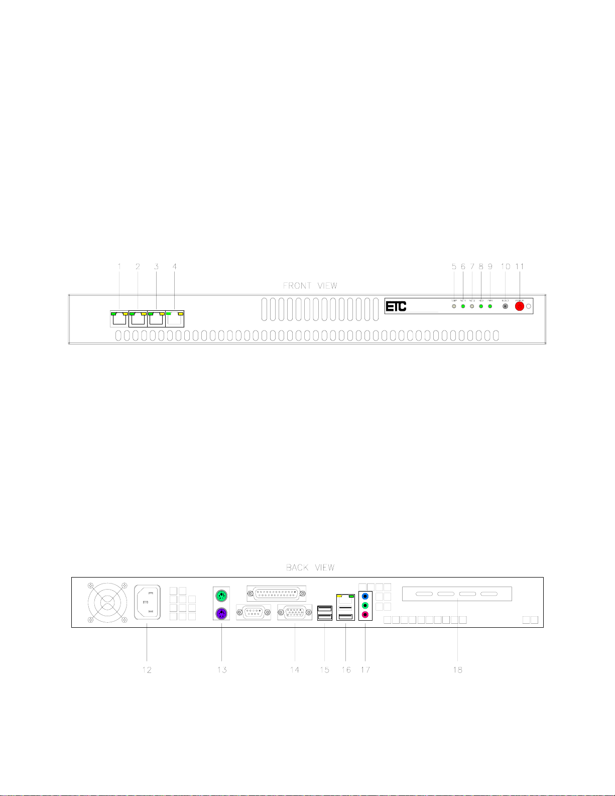
Note: The DS-1800 has EIGHT (8) RJ45 ports instead of only FOUR (4) as shown in (Figure E).
Front View (Figure E):
(1-4) Analog Ports – RJ45 EIA/TIA 568b, balanced, transformer isolated, 600 Ohm, full duplex
(5) TEMP -
(6) NET 1 -
(7) NET 2 -
(8) HDD – Provides front panel indication of Hard Drive activity
(9) PWR – Provides front panel indication of the unit’s on/off status
(10) RESET – Provides front panel access to manually reset the gateway
(11) POWER – Power ON/OFF switch
Figure E
Back View (Figure F):
(12) 120 VAC power connection
(13) Keyboard and Mouse connection
(14) VGA port connection to local monitor or KVM
(15) Spare USB ports
(16) NIC (Ethernet) and primary USB ports
(17) On board sound audio I/O (Not Used)
(18) Expansion slot to allow installation of 3rd party add on cards when applicable
Figure F
.
“E & M” Functionality

DS-1400/1800 Installation Guide Rev 05.12 Page 5 of 15 Essential Trading Systems Corp.
“M” Lead (Tx): Both the VG-1400 and VG-1800 have the “M” Lead option of adjustable time-
delay P
Pu
us
sh
h
T
To
o
T
Tr
ra
an
ns
sm
mi
it
t
(
(P
PT
TT
T)
)
c
co
on
nt
ta
ac
ct
t
c
cl
lo
os
su
ur
re
e. The “M” Lead option becomes critical in
matching transmit delay to equipment key-up time. Each of the four channels has a dedicated
16 position adjusting switch (Figure H). Included on the back of the board is a label (Figure I)
showing the switch adjustment position to time delay correlation (Figure J). The PTT Dry
Contact is a solid state non-polarized Normally Open (NO) relay. Specification maximum values
are 100VDC max. Open; 150mA current and 8Ωmax resistance Closed.
Figure G Figure H Figure I
“E” Lead (Rx): Only the VG-1400 has the option of requiring a switch T
To
o
E
En
na
ab
bl
le
e
R
Rx
x
or having
A
Al
lw
wa
ay
ys
s
A
Ac
ct
ti
iv
ve
e
R
Rx
x.
.
The “E” Lead option becomes critical in LMR situations where background
noise can be interpreted as an analog signal. Thus, having Rx disabled unless the VG-400
receives a viable switch signal avoids noise. Pair 3 is designated as “E” Lead Rx with Pin 3 as
Ground and Pin 6 as logic level +3.3VDC. Pulling or “Pinning Up” Pin 3 to Pin 6 is what enables
Rx to activate. The DS-1400 uses jumper JP1 (Figure J) to globally enable or disable this
feature.
•By positioning JP1 in “E & M” mode, the board
requires a switch signal T
To
o
E
En
na
ab
bl
le
e
R
Rx
x.
•By positioning JP1 in “On” mode, which is the factory
default setting (Figure J), the board does not require a
switch signal and is A
Al
lw
wa
ay
ys
s
A
Ac
ct
ti
iv
ve
e
R
Rx
x.
.
FigureJ
To access these settings, remove the top cover of the DS-1400/1800.
Position Delay - mS
0 45
1 90
2 130
3 180
4 220
5 260
6 300
7 350
8 400
9 450
A 480
B 530
C 570
D 620
E 660
F 700
DS-1400/1800 Installation Guide Rev 05.12 Page 6 of 15 Essential Trading Systems Corp.
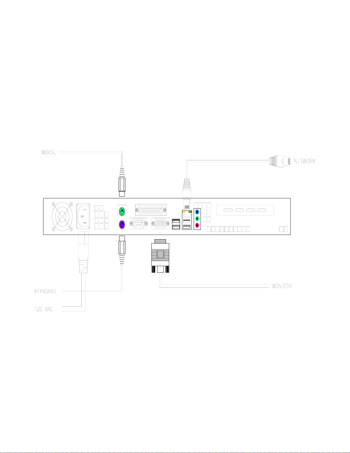
Hardware Connections
Note: It is recommended that connections, as indicated below, be in place prior to initial power
up.
The basic connections necessary to ensure successful installation are shown in (Figure K). A
local keyboard, mouse & monitor (not provided) connected to the DS-1400/1800 will aid with
configuration and diagnostic activity. The network port should be connected to an appropriate
Ethernet switch for LAN/WAN connectivity. The DS-1400/1800 is factory configured for DHCP
but can be configured with a static IP address upon request.
Figure K
After all external hardware components have been connected as recommended; the DS-
1400/1800 is ready to be powered up. The device has been factory preconfigured to
automatically logon with a preset username & password, typically “administrator & password”
respectively. The username and password can be changed anytime after initial power up to
comply with specific network security measures. After the DS-1400/1800 has completed its boot
up sequence, the Windows settings must be configured.

DS-1400/1800 Installation Guide Rev 05.12 Page 7 of 15 Essential Trading Systems Corp.
Windows XP Audio Device Hardware Configuration
NOTE: This manual was created using Windows XP Pro operating system. If you are running
another Windows operating system, your screens may look different.
Click on S
So
ou
un
nd
ds
s,
,
S
Sp
pe
ee
ec
ch
h,
,
a
an
nd
d
A
Au
ud
di
io
o
D
De
ev
vi
ic
ce
es
s icon located in the C
Co
on
nt
tr
ro
ol
l
P
Pa
an
ne
el
l
(Figure 1).
Figure 1
Click on the S
So
ou
un
nd
ds
s
a
an
nd
d
A
Au
ud
di
io
o
D
De
ev
vi
ic
ce
es
s icon (Figure 2).
Figure 2

DS-1400/1800 Installation Guide Rev 05.12 Page 8 of 15 Essential Trading Systems Corp.
In the S
So
ou
un
nd
ds
s
a
an
nd
d
A
Au
ud
di
io
o
D
De
ev
vi
ic
ce
es
s
P
Pr
ro
op
pe
er
rt
ti
ie
es
s window you will see ETC VoIP Ch. 4 as
the default speaker (Figure 3). This needs to be changed to ETC VoIP Ch.1. Click on the A
Au
ud
di
io
o
tab (Figure 4).
Figure 3 Figure 4
Click on the S
So
ou
un
nd
d
P
Pl
la
ay
yb
ba
ac
ck
k
D
De
ef
fa
au
ul
lt
t
D
De
ev
vi
ic
ce
e drop down menu and choose ETC VoIP Ch.1.
(Figure 5). Click on the S
So
ou
un
nd
d
R
Re
ec
co
or
rd
di
in
ng
g
D
De
ef
fa
au
ul
lt
t
D
De
ev
vi
ic
ce
e drop down menu and choose ETC
VoIP Ch.1 (Figure 6)
Figure 5 Figure 6

DS-1400/1800 Installation Guide Rev 05.12 Page 9 of 15 Essential Trading Systems Corp.
Click the A
Ap
pp
pl
ly
y button (Figure 7). Click on the V
Vo
ol
lu
um
me
e tab and the check “P
Pl
la
ac
ce
e
v
vo
ol
lu
um
me
e
i
ic
co
on
n
i
in
n
t
th
he
e
t
ta
as
sk
kb
ba
ar
r” box so you can access these settings quicker in the future if needed (Figure 8).
Figure 7 Figure 8
To optimize DS-1400/1800 performance, sound card settings must be adjusted after device
installation. Click on the A
Ad
dv
va
an
nc
ce
ed
d button in the D
De
ev
vi
ic
ce
e
v
vo
ol
lu
um
me
e box (Figure 9). The ETC VoIP
Ch. 1 S
Sp
pe
ea
ak
ke
er
r mixer window will open. If your window does NOT show a M
Mi
ic
cr
ro
op
ph
ho
on
ne
e device
you will need to activate it. From the O
Op
pt
ti
io
on
ns
s drop down menu choose P
Pr
ro
op
pe
er
rt
ti
ie
es
s (Figure 10)
Figure 9 Figure 10

DS-1400/1800 Installation Guide Rev 05.12 Page 10 of 15 Essential Trading Systems Corp.
In the P
Pr
ro
op
pe
er
rt
ti
ie
es
s window
check the M
Mi
ic
cr
ro
op
ph
ho
on
ne
e box (Figure 11) then click the O
OK
K button. You
will see a M
Mi
ic
cr
ro
op
ph
ho
on
ne
e device for ETC VoIP Ch. 1 in the S
Sp
pe
ea
ak
ke
er
r window. Using your cursor,
move the S
Sp
pe
ea
ak
ke
er
r
(master) volume lever up to the recommended playback level shown (Figure
12)
Figure 11 Figure 12
The M
Mi
ic
cr
ro
op
ph
ho
on
ne
e
volume lever must be down all the way and the M
Mu
ut
te
e
b
bo
ox
x
m
mu
us
st
t
b
be
e
c
ch
he
ec
ck
ke
ed
d
(
(F
Fi
ig
gu
ur
re
e
1
13
3)
)
Figure 13

DS-1400/1800 Installation Guide Rev 05.12 Page 11 of 15 Essential Trading Systems Corp.
ATTENTION:
The microphone Mute
box must be checked.
An unchecked Mute box
will cause echo on the
network and down-time
for troubleshooting your
installation.
From the O
Op
pt
ti
io
on
ns
s drop down menu choose P
Pr
ro
op
pe
er
rt
ti
ie
es
s (Figure 14). In the P
Pr
ro
op
pe
er
rt
ti
ie
es
s window click
on the M
Mi
ix
xe
er
r
d
de
ev
vi
ic
ce
e drop down menu and choose the next ETC channel to configure (Figure 15).
Figure 14 Figure 15

DS-1400/1800 Installation Guide Rev 05.12 Page 12 of 15 Essential Trading Systems Corp.
Check the M
Mi
ic
cr
ro
op
ph
ho
on
ne
e box then click the O
OK
K button (Figure 16) to return to the S
Sp
pe
ea
ak
ke
er
r mixer
window and repeat the procedure for all four/eight ETC channels. The Recording volume for all
devices can now be adjusted. From the O
Op
pt
ti
io
on
ns
s drop down menu choose P
Pr
ro
op
pe
er
rt
ti
ie
es
s (Figure 17).
Figure 16 Figure 17
In the P
Pr
ro
op
pe
er
rt
ti
ie
es
s window click on the R
Re
ec
co
or
rd
di
in
ng
g circle and click the O
OK
K
button (Figure 18). The
W
Wa
av
ve
e
I
In
n (recording level) window will appear. Adjust the volume to the recommended level
(Figure 19). From the O
Op
pt
ti
io
on
ns
s drop down menu choose P
Pr
ro
op
pe
er
rt
ti
ie
es
s (Figure 20).
.
Figure 18 Figure 19 Figure 20

DS-1400/1800 Installation Guide Rev 05.12 Page 13 of 15 Essential Trading Systems Corp.
In the P
Pr
ro
op
pe
er
rt
ti
ie
es
s window click on the M
Mi
ix
xe
er
r
d
de
ev
vi
ic
ce
e drop down menu and choose the next ETC
channel to configure (Figure 21). Click the O
OK
K
button
to return to the W
Wa
av
ve
e
I
In
n window, adjust
the volume,
and repeat the procedure for all four/eight ETC channels (Figure 22)
Figure 21 Figure 22
After all four/eight ETC channels have been configured, close out the W
Wa
av
ve
e
I
In
n window, and any
other windows left open, and your DS-1400/1800 is ready to go.

DS-1400/1800 Installation Guide Rev 05.12 Page 14 of 15 Essential Trading Systems Corp.
Specifications
4 USB 2.0 Compliant Ports
Frequency Response: 200Hz-5kHz @ -3dB
Level: -50dB to 0dB Input
Distortion: <.2% at 1kHz
ERL: <-70dB
FSB 1066 MHz (DS 1400 only)
10/100/1000 mbps High speed Ethernet NIC
Audio Inputs – 600 Ohm, Transformer Isolated
Audio Outputs – 600 Ohm, Transformer Isolated
4 Analog COR/PTT/E&M Audio ports (DS1400 only))
2GB DDR Memory (RAM)
Intel 2.93GHz (R) VT Core (TM) 2 Duo Processor E7500
Processor Speed – minimum 1.6GHz
Storage – 160 GB Hard Drive
Operating System – Embedded XP Pro
Power – 120 VAC, 95 Watts
Dimensions – H 1.75” x W 19” x D 14.5” (1 Rack Unit)
Environmental Requirements:
5◦-35◦C (50◦-95◦F) operating temp
10%-90% non-condensing relative humidity
Analog Port Pin Out
Each analog output is an RJ-45 conforming to EIA/TIA 568b standards.
The pin out is as follows (in reference to the device’s analog port):
Pair Pin Color Description
1 4 Blu/Wht Receive, Tip (RxT)
5 Wht/Blu Receive, Ring (RxR)
2 1 Wht/Org Transmit, Tip (TxT)
2 Org/Wht Transmit, Ring (TxR)
3 3 Wht/Grn “E” Lead, (Rx)
6 Grn/Wht “E” Lead, (Rx)
4 7 Wht/Brn “M” Lead, N.O. PTT (Tx)
8 Brn/Wht “M” Lead, N.O. PTT (Tx)
“M” Lead Tx: “E” Lead Rx:
Pins 7 &8 of Pair 4 Pins 3 & 6 of Pair 3
100VDC Max @ Open 3.3VDC Logic
N.O. Solid State Non Polarized Relay. 3mA Closed or GND
150mA and 8ΩMax @ Closed

DS-1400/1800 Installation Guide Rev 05.12 Page 15 of 15 Essential Trading Systems Corp.
VG-1400/1800 Hardware Product Limited Warranty
ETC warrants that your ETC hardware product shall be free from defects in material and workmanship for
One Year, beginning from the date of purchase. Except where prohibited by applicable law, this warranty
is nontransferable and is limited to the original purchaser. This warranty gives you specific legal rights,
and you may also have other rights that vary under local laws
ETC’s entire liability and your exclusive remedy for any breach of warranty shall be, at ETC’s option, (1)
to repair or replace the hardware, or (2) to refund the price paid, provided that the hardware is returned to
the point of purchase or such other place as ETC may direct with a copy of the sales receipt or dated
itemized receipt. Shipping and handling charges may apply except where prohibited by applicable law.
ETC may, at its option, use new or refurbished or used parts in good working condition to repair or
replace any hardware product. Any replacement hardware product will be warranted for the remainder of
the original warranty period or thirty (30) days, whichever is longer or for any additional period of time that
may be applicable in your jurisdiction. This warranty does not cover problems or damage resulting from
(1) accident, abuse, misapplication, or any unauthorized repair, modification or disassembly; (2) improper
operation or maintenance, usage not in accordance with product instructions or connection to improper
voltage supply; or (3) use of consumables, such as replacement batteries, not supplied by ETC except
where such restriction is prohibited by applicable law.
Before submitting a warranty claim, we recommend you contact ETC support at
through the point of purchase during the first thirty (30) days after purchase; however, this period of time
may vary depending on where you purchased your product – please check with ETC for details. Warranty
claims or other product related questions should be addressed directly to ETC. The addresses and
customer service contact information for ETC can be found in the documentation accompanying your
product and on the web at www.essentialtel.com.
ETC SHALL NOT BE LIABLE FOR ANY SPECIAL, INDIRECT, INCIDENTAL OR CONSEQUENTIAL
DAMAGES WHATSOEVER, INCLUDING BUT NOT LIMITED TO LOSS OF PROFITS, REVENUE OR
DATA (WHETHER DIRECT OR INDIRECT) OR COMMERCIAL LOSS FOR BREACH OF ANY
EXPRESS OR IMPLIED WARRANTY ON YOUR PRODUCT EVEN IF ETC HAS BEEN ADVISED OF
THE POSSIBILITY OF SUCH DAMAGES. Some jurisdictions do not allow the exclusion or limitation of
special, indirect, incidental or consequential damages, so the above limitation or exclusion may not apply
to you.
©Essential Trading Systems Corps. All intellectual property rights in this publication are owned by
Essential Trading Systems Corps. and are protected by United States copyright laws, other applicable
copyright laws and international treaty provisions. Essential Trading Systems Corps. Retains all rights not
expressly granted. No part of this publication may be reproduced in any form whatsoever or used to
make any derivative work without prior written approval by Essential Trading Systems Corps. No
representation of warranties for fitness for any purpose other than what is specifically mentioned in this
guide is made either by Essential Trading Systems Corps. or its agents. Essential Trading Systems Corp.
reserves the right to revise this publication and make changes without obligation to notify any person of
such revisions or changes. Essential Trading Systems Corps. may make improvements or changes in the
product(s) and/or the program(s) described in this documentation at any time. All rights reserved.
Endorsement of ETC or ETC’s products is not implied by use of other companies product names
Windows® is a registered trademark of Microsoft Corporation in the United States and other countries
WAVE® is a registered trademark of Twisted Pair Solutions, Inc.
This manual suits for next models
1
Table of contents
Popular Gateway manuals by other brands

Shiratech
Shiratech IoT-Box quick start guide

VoiceInterop
VoiceInterop AudioMate AM360r user guide

Quick
Quick QNN Installation and use manual

RTA
RTA 460PBSDFM-N70PB Product user guide

Ruckus Wireless
Ruckus Wireless ZoneDirector ZD1100 Upgrade instructions

SST Automation
SST Automation SSTCOMM GT200-MT-RS485 user manual


