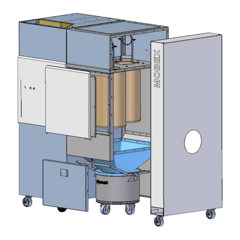
Esta MOBEX F W3 User manual

Operating Instructions
MOBEX F W3
(Hazardous substance-verified, welding fume separation class W3)
MOBEX F-40 W3 (Order no.: 09835)
MOBEX F-60 W3 (Order no.: 09836)
and variations
Do not use this device unless you have
read the user manual and understand it.
Translation of the original instructions
09835-08-01

2 MOBEX F W3 09835-52-01
Edition notice
Original operating instructions
Document no..: 09835-08-01
Publishing date: 30/04/2014
Type of device: Stationary welding fume filter MOBEX F W3
Item no.: 09.835 // 09.836 and versions
Publisher
ESTA Apparatebau GmbH & Co. KG Tel.: +49 (0) 73 07 80 4 -0
Gotenstr. 2-6 Fax: +49 (0) 73 07 80 4 -500
Germany www.esta.com
Copyright notice (per DIN ISO 16016:2007-12)
Transfer or reproduction of this document, or the use or communication of its content, is
forbidden without explicit consent. Violators will be liable for damages. All rights to patent, utility
or design registration are reserved.

09835-52-01 MOBEX F W3 3
Contents
Contents.................................................................................................................................3
1.General instructions........................................................................................................5
2.Product identification......................................................................................................6
2.1 Technical data .............................................................................................................6
2.2Intended application................................................................................................6
2.2.1Ambient conditions....................................................................................................6
2.2.2Intended use .............................................................................................................7
2.2.3Improper use.............................................................................................................7
2.2.4Reasonably foreseeable misuse ...............................................................................8
3.Product description.........................................................................................................8
3.1Picture of the device ...............................................................................................8
3.1.1MOBEX F-40 W3 ......................................................................................................8
3.1.2MOBEX F-60 W3 ......................................................................................................8
3.2Functional description .............................................................................................9
3.3Monitoring the minimum airflow volume................................................................10
4.Safety instructions........................................................................................................11
4.1Hazard categories................................................................................................. 11
4.2Symbol explanation............................................................................................... 11
4.2.1Symbols on the device ............................................................................................ 12
4.3General safety instructions ...................................................................................13
4.4.Preventing mechanical hazards............................................................................13
4.5Preventing electrical hazards................................................................................14
4.6.Preventing dust hazards ....................................................................................... 15
4.7Preventing noise hazards .....................................................................................16
5.Delivery and commissioning........................................................................................17
5.1Delivery and transport...........................................................................................17
5.2Connection............................................................................................................17
5.2.1Control cabinet description......................................................................................18
5.2.2Pneumatic connection............................................................................................. 19
5.2.3Electrical connection ...............................................................................................19
5.2.4Activation operations for motors:.............................................................................20
5.3Function check......................................................................................................21
5.3.1Rotation direction monitoring ..................................................................................21
5.4Preparing the dust collection containers ...............................................................22
5.4.1Base body ...............................................................................................................22
5.4.2 Lid for dust collection containers............................................................................. 23
5.5Commissioning .....................................................................................................24
5.6Suction line connection .........................................................................................25
5.7Troubleshooting during commissioning.................................................................26
6.Operating instructions..................................................................................................27
6.1Operating the device.............................................................................................27
6.2Jet pulse cleaning .................................................................................................27
6.2.1Automatic cleaning during suction operation (online filter cleaning).......................28
6.2.2Automatic post-cleaning..........................................................................................28
6.2.3Manual cleaning (only possible during operation) ...................................................28

4 MOBEX F W3 09835-52-01
7.Maintenance & troubleshooting...................................................................................29
7.1Maintenance instructions ......................................................................................29
7.2Inspection and maintenance intervals...................................................................30
7.2.1Spare and wear parts.............................................................................................. 32
7.3Clean the air guide plate .......................................................................................33
7.3.1At MOBEX P-24 ......................................................................................................34
7.3.2At MOBEX P-36 ......................................................................................................35
7.4Replacing the dust collection container................................................................. 36
7.5Replacing filter cartridges .....................................................................................37
7.6Setting the minimum airflow volume monitoring....................................................40
7.6.1MOBEX F-40 W3 ....................................................................................................41
7.6.2MOBEX F-60 W3 ....................................................................................................41
7.7Detach filter mat fan.............................................................................................. 42
7.8Detach filter mat outlet ..........................................................................................43
7.9Clean the device ...................................................................................................44
7.10Store the device .................................................................................................... 44
7.11Troubleshooting ....................................................................................................45
8.Disposal .........................................................................................................................47
8.1Dispose of the dust collected ................................................................................47
8.2Dispose of used filter cartridges............................................................................ 47
8.3Dispose of the device............................................................................................ 48
9.Optional equipment.......................................................................................................49
9.1Start-up with potential-free contact .......................................................................49
9.1.1Installation on the potential-free contact..................................................................49
9.2Mobile design........................................................................................................50
9.3Spark pre-separator (SPS) ................................................................................... 52
9.3.1Cleaning the spark pre-separator............................................................................53
9.3.2Checking and cleaning the material pre-separator.................................................. 54
9.3.3Checking and cleaning the coarse dust collection drawer....................................... 55
9.4Spark detection .....................................................................................................56
9.4.1Fire-extinguishing device ........................................................................................56
9.5Air vents................................................................................................................ 57
9.6Alternative filter cartridges ....................................................................................58
9.6.1Pre-coating when installing new pre-coatable filter cartridges ................................58
9.6.2Minimum volume flow monitoring MOBEX F-40 W3 ...............................................59
9.6.3Minimum volume flow monitoring MOBEX F-60 W3 ...............................................60
10.EC Declaration of Conformity ......................................................................................61
Notes.....................................................................................................................................62
Notes.....................................................................................................................................63

09835-52-01 MOBEX F W3 5
1. General instructions
Before operation, all persons who are to use the device or perform maintenance
on it must be provided with information, instructions and training in using the
device and on the substances for which it is to be used, including the procedure
for safe disposal of the collected material. Responsibilities must be clearly
established for the following:
Installation
Commissioning
Operation
Maintenance and repairs
Read the operating manual carefully before working with the device.
The device must be used only by persons who have been instructed in its
handling and are explicitly authorised to use it.
Always keep the operating manual at the place where the device is being used, so
that it can be seen by personnel at all times.

6 MOBEX F W3 09835-52-01
2. Product identification
2.1 Technical data
We reserve the right to make technical changes.
Item no. 09835 09836
Type MOBEX F-40 W3 F-60 W3
Filter type Filter cartridge
Number of filter elements [units] 2 3
Filter area [m²] 40 60
Max. vacuum [Pa] 3,400 3,400
Max. volume flow [m³/h] 2,800 4,500
Drive power [kW] 3.0 4.0
Connection voltage [V] 400
Nominal frequency [Hz] 50
Nominal current [A] 7 9
Circuit breaker [A] C16A (circuit breaker)
Protection class IP 54
Dust collection drawer [l] 100 - 150
Dust collection container (per ~38
litres) [units] 2
Intake connection piece ø[mm] 200 250
Dimensions (L x W x H) [mm] 1,910 x 1,040 x 2,030 2,030 x 1,040 x 2,030
Average sound pressure level Lpa [dBA] 71 74
Weight [kg] approx. 310 approx. 350
Production year See model plate
* using the enveloping surface method DIN EN ISO 3744, measured at minimum volume flow; noise measurement margin
of error approx. 4 dBA
2.2 Intended application
2.2.1 Ambient conditions
Ambient temperature [°C] 540
Rel. humidity [%] 30 - 70

09835-52-01 MOBEX F W3 7
2.2.2 Intended use
The device has been manufactured based on state-of-the-art technology and
according to recognized safety regulations and must be used as intended:
For commercial use, such as in industrial enterprises and workshops.
For the separation of dry, non-flammable welding fumes.
For the separation of smoke from unalloyed and low-alloy steels; e.g. with
low nickel and chrome content.
For the separation of smoke from steels with an alloy content of, for
example, nickel and chrome ≤30%.
For the extraction of smoke from high-alloy steels.
For extraction at individual welding workstations.
As a central extraction system for multiple welding workstations.
Only for dry cleaning.
Other applications are considered unintended use. ESTA is not liable for damages
due to unintended use!
The manufacturer sets up the device according to the operator’s information.
2.2.3 Improper use
The device has been manufactured according to the state of the art and
recognized safety regulations. Unintended use may cause hazards.
Therefore:
Not for extracting welding fumes during the welding of oil-covered parts.
Not for the extraction of flammable welding fumes.
Do not use or store outdoors or in wet conditions.
Do not change the location of the device during suction operation.
Do not set up or operate in dust/gas-explosive areas.
Do not use in painting operations.
Do not connect to processing machines that may produce active ignition
sparks or hot embers.
Do not suck up readily flammable or glowing particles.
Do not suck up liquids.
Do not suck up aggressive gases.

8 MOBEX F W3 09835-52-01
2.2.4 Reasonably foreseeable misuse
Do not suck up hot embers, such as cigarette butts.
Do not cause complete closure of the suction ports.
3. Product description
3.1 Picture of the device
3.1.1 MOBEX F-40 W3
3.1.2 MOBEX F-60 W3
Intake port
Dust collection
drawer
Switch box
Cover
Fan Unit
Filter unit
Dust collection
drawer
Switch box
Filter unit
Intake port
Cover
Fan Unit
Inlet element
Inlet element
Inspection cover

09835-52-01 MOBEX F W3 9
3.2 Functional description
The device is equipped with a three-phase motor which drives a radial fan. The
device is supplied with or disconnected from the requisite power via a main switch.
The device starts up immediately once turned on at the main switch.
The vacuum created by the fan draws air through the suction pipe or hose
connected to the intake port. Permanent filters within the filter housing extract the
dust in the extracted air. The purified air is guided back into the room draught-free
through the outlets on the top of the device.
With the filter cartridges used, the device is equipped with a vacuum monitor as a
control device for overseeing minimum airflow volume. This control device
measures the negative pressure behind the filters. With increased dust soiling of
the filters, the flow resistance increases along with the negative pressure behind
the filter.
Once the value set on the vacuum monitor is reached, an optical/acoustic signal
indicates this and the filter cartridges are automatically cleaned with compressed
air. A pneumatic jet pulse cleaning device is integrated for this purpose. Intense
pulses of compressed air are successively introduced into the filter cartridges. As
a result, the filter elements are freed of dust and regenerated. The dust collection
container attached below the filter collects the dust that has been cleaned off. If
the filter cartridges continue to clog, and the set minimum volume flow is thus
reached in the device, this will be indicated by an optical/acoustic signal. System
shutdown and inspection is mandatory.
For easy disposal of the collected dust, the dust collection drawer is unloaded,
pulled out, the dust collection container tightly sealed with a lid and sticky tape and
the dust collection container taken out including its contents.
The device is fitted with a pre-separator / baffle. This pre-separator / baffle is
installed in front of the actual filters, behind the intake connection piece, which
pre-separates coarse particles and thus prevents these coarse particles being
sucked against the filter. The pre-separator / baffle must be checked regularly for
soiling. When doing this, please follow the safety instructions for cleaning.

10 MOBEX F W3 09835-52-01
3.3 Monitoring the minimum airflow volume
The minimum volume flow is monitored through differential pressure
measurement. This is integrated within the switch cabinet. If the nominal volume
flow set at the factory is fallen short of, the automatic cleaning of the filter
cartridges begins. The filter cartridges are automatically cleaned with compressed
air. Once the minimum volume flow set in the device has been reached, this is
indicated by an optical/acoustic signal. System shutdown and inspection is
mandatory.
Extraction elements with various intake connection piece diameters can be
operated with the device. When so doing, you must ensure that
The minimum airflow volume sucked away is not undershot.
- The minimum airflow volume depends on the diameter of the intake
connection piece of the extraction element and the requisite
conveying velocity.

09835-52-01 MOBEX F W3 11
4. Safety instructions
4.1 Hazard categories
Safety instructions and cross-topic information are indicated in this manual by
symbols.
Based on the severity of the hazard, the hazard warnings are categorized as
follows:
DANGER
Hazard warning about an immediate danger to people.
Failure to comply can lead to severe injury or death.
WARNING
Warning about a recognisable hazard.
Failure to comply can lead to severe injury or death, and can destroy the device or
parts thereof.
CAUTION
Instruction about a hazard.
Failure to comply can lead to mild injury and to damage to the device.
4.2 Symbol explanation
Further information
Reference to ESTA customer service
Reference to legal regulations

12 MOBEX F W3 09835-52-01
4.2.1 Symbols on the device
Switch off the device.
Wait 5 minutes.
Then pull out the dust collection drawer or open the device.
Before commissioning, read and observe the operating manual and safety
instructions (per ISO 11684)
Warning of hand injuries (as per BGV A8 W27)
Load the area only briefly with a maximum of 175 kg.
Do not take in glowing dust or other sources of ignition. Do not use in
conjunction with spark-generating machinery.
The device complies with welding fume separation class W3. Separation
efficiency (as per DIN EN 15012-1) of ≥99% is reliably maintained!

09835-52-01 MOBEX F W3 13
4.3 General safety instructions
During extraction, the volume flow returned from the device into the room should
be no more than 50% of the air supplied. With open room ventilation, supply air
flow should be assumed as equal to the room volume every hour. This means that
the rate of air replacement must be once per hour.
Supply air flow [m³/h] = Room volume [m³] Air replacement rate [1/h]
Example:
When the device is operating at the nominal airflow volume of 1,060 m³/h, the
same volume of fresh air must be fed in. This occurs with natural ventilation if the
volume of the work room is 1,060 m³ (e.g., 353 m² surface with a 3 m ceiling
height).
According to work equipment user directives 2009/104/EC and TRGS 560, safety
devices for prevention or removal of hazards must be regularly maintained and
regularly inspected by an expert for safe, flawless operation.
In all emergencies, the device must be disconnected from the power supply
immediately, turned off at the main switch and the plug pulled immediately.
If there is a fire, alert the fire department immediately, and contain the fire by
appropriate means. Therefore keep a suitable extinguishing agent near the device
before start-up and during operation.
4.4. Preventing mechanical hazards
WARNING
Crushing hazard due to loose or open covers
Keep covers closed during operation!
All movable machine parts driven by electric motors must be covered by fixed,
securely fastened protective covers that can be removed only with tools.

14 MOBEX F W3 09835-52-01
4.5 Preventing electrical hazards
DANGER
Electric shock from high voltages
Follow the safety rules for working with electrical devices!
Secure the device against reactivation with a padlock!
Render the device voltage-free by pulling the mains connector!
Any work on the electrical grid and on voltage-conducting parts may only
be performed by an electrical specialist.
DANGER
Electric shock from high voltages when power cable is damaged
Do not damage by running over, crushing, straining, etc.
Regularly check the power cable for damage and ageing.
Do not use if damage has been found on the power cable!
Any work on the electrical grid and on voltage-conducting parts may only
be performed by an electrical specialist.
Use only original ESTA replacement parts.
DANGER
High-voltage electric shock when working on the open switch box
Turn off at the main switch and secure with a padlock against reactivation!
Render the device voltage-free by pulling the mains connector!
Any work on the electrical grid and on voltage-conducting parts may only
be performed by an electrical specialist.
DANGER
Residual hazard from loose or open covers
Keep covers closed during operation!
Any work on the electrical grid and on voltage-conducting parts may only
be performed by an electrical specialist.
All electrical parts must be covered by fixed, securely fastened protective covers
that can be removed only with tools. The device complies with Protection Class I
according to EN 60 335.
After use, before moving the device to another site and before cleaning,
maintenance, or replacement or removal of movable parts, switch off the system
at the main switch and pull the mains connector.

09835-52-01 MOBEX F W3 15
4.6. Preventing dust hazards
CAUTION
Damage due to dust release
Maintenance, cleaning, servicing and emptying work only by specialist
personnel.
Wear personal protective gear.
- Respirator mask (particle filter class P3)
- Protective clothing
- Protective gloves
Set up locally filtered forced-air ventilation where the device is being
maintained, inspected or cleaned.
Operate the device only with the complete filtration system.
Seal the intake connection piece with a sealing plug so it is dust-tight when
transporting.
CAUTION
Damage from dust release when cleaning filter media (cartridges, mats, etc.) in a
dismantled state.
Used filter media must never be cleaned through blowing or beating them
out!
Always dispose of used filter media packaged in an airtight condition in
accordance with local regulations!
CAUTION
Damage due to dust build-up in the pipe system
Check the connected piping system regularly for dust deposits.
Observe the minimum air speed for your application and the resulting
minimum airflow volume.
When removing the dust collection container, it is possible to
inhale dust. That is why all servicing, cleaning and maintenance
procedures, including the removal and emptying of the dust
collection container, are only to be performed by specialist
personal with personal protective equipment.
The people assigned to cleaning work must be instructed on the
aspirated toxic materials. Harm to bystanders and the
environment must be prevented by all means. Clean the
maintenance area thoroughly once maintenance is complete.

16 MOBEX F W3 09835-52-01
4.7 Preventing noise hazards
CAUTION
Danger of hearing damage from release of compressed air impulses when filter
elements are being cleaned
Keep device covers closed.
Wear hearing protection.
Only open the device with the compressed air tank depressurised.
To do this:
- Turn the device off at the main switch
- Wait for the automatic post-cleaning to end
- Disconnect the compressed air supply directly from the switch
cabinet
- Empty the compressed air tank – through "Start cleaning" if
necessary
Only open the device when stopped.
To do this:
- Cut off the power supply by pulling the electrical plug
If the device, in particular the cleaning module, has to be opened during operation,
the automatic cleaning can be started by the control system during normal
operation. Cleaning pulse forces are harmful to human ears. The manometer
attached to the compressed air tank is used for monitoring the pressure in the
tank.
After use, before moving the device to another site and before cleaning,
maintenance, or replacement or removal of movable parts, disconnect the
compressed air at the switch cabinet.

09835-52-01 MOBEX F W3 17
5. Delivery and commissioning
5.1 Delivery and transport
DANGER
Danger from falling device
Do not walk under heavy loads.
The lifting equipment must be designed for the weight of the device.
WARNING
Crushing hazard if the device settles during transport
Secure the device during transport.
Wear safety shoes.
CAUTION
Risk of damaging the device due to improper transport.
Do not push the device over the floor if it does not have any rollers.
Use only suitable lifting equipment (such as a crane) and transport
equipment (such as a forklift or lift truck) when transporting the device to its
set-up location.
Watch out for the centre of gravity – which is not in the centre – when
positioning.
Make sure the floor has adequate weight capacity and can be properly driven on
when transporting the device.
At delivery, the device is fastened to a pallet. Remove the protective cover and
floor securing devices. Inspect the delivery for completeness. Lift the device with a
crane or forklift from eye hooks positioned at the top of the device. Please pay
attention to the weight of the device and its high centre of gravity during all
transport work.
Upon delivery, please inspect the device for transportation damage. Damage
determined must be reported and documented immediately.
ESTA customer service: +49 (0) 7307 804 - 0
5.2 Connection
Before establishing cable connections between the device and the mains, check
whether the operating voltage specified on the rating plate matches that of the
mains.
Place the device on an even surface as close as possible to the welding fume
source. Ensure the device is aligned horizontally when setting it up. To do this use
the small packing plate enclosed with the delivery as assembly material.

18 MOBEX F W3 09835-52-01
5.2.1 Control cabinet description
The switch cabinet is equipped with the following elements.
MAIN SWITCH
Device main switch for turning the device on and off. The device starts up
immediately following activation.
This can be secured with a lock against unintentional activation.
START CLEANING (pushbutton)
Is used for the manual starting of the cleaning equipment.
PHASE SEQUENCE CONTROL (light in pushbutton)
Lights up when the electrical rotating field is incorrect at start-up.
POWER CONNECTION
For the connection to the required power supply. The mains connector is
simultaneously used to isolate the device. In the event of an emergency, pull this
as EMERGENCY OFF.
COMPRESSED AIR CONNECTION
For the connection to the required compressed air supply.
SIGNALLING DEVICE
The signalling device is used as an optical/acoustic signal for warning of
extraordinary operating conditions, such as the undershooting of the minimum
flow volume.
ATMOSPHERE CONNECTION
For measuring the pressure against the atmosphere. In connection with the
negative pressure measured in the device, this provides the differential pressure.
Main switch
Start cleaning
Phase sequence
control
Compressed air
connection
Power connection
Atmosphere
connection
Signalling device

09835-52-01 MOBEX F W3 19
5.2.2 Pneumatic connection
WARNING
Risk of corrosion when using unfiltered compressed air.
Use a compressed air maintenance unit to make sure that only oil- and
water-free compressed air is fed to the device.
Compressed air is required for the pneumatic jet pulse cleaning of the filter
elements. Connect oil and water-free compressed air to ensure operational
safety and machine availability.
The connection to the compressed air system is made at the installation
location.
MOBEX
F-40 W3 F-60 W3
Pressure [bar] 4 - 6
Connection-ø [''] 1/4 (ø9mm)
Compressed air consumption * [l/pulse] 19
Manometer settings [bar] 3
* at 4 bar with a valve opening time of 0.12 sec.
5.2.3 Electrical connection
DANGER
Electric shock from high voltages
Follow the safety rules for working with electrical devices!
Secure the main switch against reactivation with a padlock when working
on the device.
Render the device voltage-free by pulling the mains connector!
Any work on the electrical grid and on voltage-conducting parts may only
be performed by an electrical specialist.
A CEE wall socket with a slow-blow fuse must be in place to supply the device
with power.
Connection to the building's power supply is made at the installation location.
* Custom voltage on request; observe the specifications on the rating plate.
Connection plug [Amp.] CEE 16 Amp.
Mains (standard)* Three-phase current
400 V; 50 Hz; 3 N~
Fuse [Amp.] C16A (circuit breaker)

20 MOBEX F W3 09835-52-01
5.2.4 Activation operations for motors:
Motors with high output without frequency converters should be not be switched
on and off within a short period of time too frequently. Otherwise, electrical
components could overload as a result. Please observe the table for activation
operations:
Motor output Activation operations per hour
1 – 4 KW Up to 8 starts
4 – 7.5 KW Up to 6 starts
7.5 – 15 KW Up to 4 starts
15 – 30 KW Up to 3 starts
From 30 KW Electronically controlled overrun time
This manual suits for next models
4
Table of contents
Other Esta Welding System manuals
Popular Welding System manuals by other brands

Panasonic
Panasonic YT-40MFW operating instructions

Lincoln Electric
Lincoln Electric HARRIS GB2 instruction manual
Scheppach
Scheppach WIG1000-Multi Translation of the original operating manual

Miller
Miller XMT 300 CC owner's manual
Ryobi
Ryobi MMA-140 Owner's operating manual
Urrea
Urrea SOLI9200-BV User manual and warranty
