IGBT MIG-200M User manual

IGBT Inverter Welder
USER’S MANUAL
Model: MIG-200M
FOR YOUR SAFETY
Read and understand this manual before use. Keep this manual for future reference

1
TABLE OF CONTENTS
1. SAFETY..................................................................................................................2
2. GENERAL DESCRIPTION................................................................……………...3
3. MAIN PARAMETERS........................................................................……………...5
4. PANEL INSTRUCTION...........................................................................................6
5. INSTALLATION......................................................................................................8
6. OPERATION.........................................................................................................11
7. CAUTION.............................................................................................................13
8. MAINTENANCE...................................................................................................14
9. DAILY CHECK......................................................................................................15
10.TROUBLE SHOOTING........................................................................................17
11.DIAGRAM.............................................................................................................19
DECLARATION OF CONFORMITY
Hereby we declare that these machines are produced based on relative
Chinese and international standards and they conform to the international safety
standard IEC60974-1. The design and technology adopted in these machines are
under patent protection.
Please read and understand this manual carefully before the installation and
operation of these machines.
1. The contents of this manual may be revised without prior notice and without
obligation.
2. Although carefully checked, there may still be some inaccuracies in this
manual. Please consult us if any.

2
Professional training is needed before operating the machine.
⚫Use labor protection welding supplies authorized by national
security supervision department.
⚫The operator must be qualified personnel with a valid "metal
welding (OFC) operations" operation certificate.
⚫Cut off power before maintenance or repair.
Electric shock—may lead to serious injury or even death.
⚫Install earth device according to the application criteria.
⚫Never touch the live parts when skin bore or wearing wet
gloves/clothes.
⚫Make sure that you are insulated from the ground and work
piece.
⚫Make sure that your working position is safe.
Smoke& gas—may be harmful to health.
⚫Keep the head away from smoke and gas to avoid inhalation
of exhaust gas from welding.
⚫Keep the working environment in good ventilation with exhaust
or ventilation equipment when welding.
Arc radiation—may damage eyes or burn skin.
⚫Wear suitable welding masks and protective clothing to protect
your eyes and body.
⚫Use suitable masks or screens to protect spectators from
harm.
Improper operation may cause fire or explosion.
⚫Welding sparks may result in a fire, so please make sure no
combustible materials nearby and pay attention to fire hazard.
⚫Have a fire extinguisher nearby, and have a trained person to
use it.
⚫Airtight container welding is forbidden
⚫Must not use the machines for other purposes except
welding, such as pipe thawing, battery charging, heating.
1. SAFETY
Welding is dangerous, and may cause damage to you and others, so take good
protection when welding. For details, please refer to the operator safety guidelines in
conformity with the accident prevention requirements of the manufacturer.

3
Hot work piece may cause severe scalding.
⚫Do not contact hot work piece with bare hands.
⚫Cooling is needed during continuous use of the welding torch.
Magnetic fields affect cardiac pacemaker.
⚫Pacemaker users should be away from the welding spot
before medical consultation.
Moving parts may lead to personal injury.
⚫Keep yourself away from moving parts such as fan.
⚫All doors, panels, covers and other protective devices should
be closed during operation.
Please seek professional help when encountering machine
failure.
⚫Consult the relevant contents of this manual if you encounter
any difficulties in installation and operation.
⚫Contact the service center of your supplier to seek
professional help if you still can not fully understand after
reading the manual or still can not solve the problem
according to the manual.
2. GENERAL DESCRIPTION
MIG-200M Welder is an inverter based MIG welder with LCD display. Adopting MCU controller,
together with TFT-LCD, it makes the setting much easier for the user.
This multi-process welder has 4 functions: Flux cored arc welding, MIG welding, TIG, and MMA;
and the MIG spool gun is optional for aluminum welding purpose.
➢Features:
◆4.2inch TFT-LCD, with high resolution, it can show the setting parameters & welding
parameters, which make it quite simple to set.
◆Adopting MCU controlling system, the welding parameters are automatically set
according to the user’s choice, which greatly improves the welding efficiency.
◆With the built-in welding expert database, it increases the welding reliability a lot.
◆Multi-process, makes it applicable for different welding purpose.

4
2.1 Flow Diagram:
2.2 Schematic Diagram:

5
3. MAIN PARAMETERS
3.1 Technical parameters table:
MODEL
MIG-200M
Input voltage (V)
1ph 230V, 50Hz
Welding mode
MIG/FLUX
MMA
TIG
Input current (A)
34
33
21
Input power(KVA)
7.5
7.2
4.7
No-load voltage(V)
60
60
60
Welding current(A)
range (A)
30~200
20~175
20~175
Welding voltage(V)
15.5~24
21~27
10.8~17
Rated duty cycle
35%
35%
35%
Welding wire dia.(mm)
0.6-1.0
N/A
N/A
Electrode dia.(mm)
N/A
1.0-4.0
N/A
Efficiency
85%
Power factor
0.7
Protection class
IP21S
Insulation class
F
* Note: The duty cycle is tested at 40°C has been determined by simulation.
* Note: The Machine with PFC version, can works under the input voltage from 85V to 260V.
While the input voltage is lower than 145V, it will switch to low voltage working mode
automatically, and the output power will be limited. Please restart the machine to recover
to the full output power, after input voltage gets to be higher than 145V.
3.2 Power supply:
MODEL
MIG-200M
Input voltage (V)
1ph 220V, 50Hz
Min. Power
Power Grid
9.5 KVA
Generator
12 KVA
Input Protection
Fuse
32 A
MCB
32 A

6
4. PANEL INSTRUCTION
4.1 Front Panel:
1. Adjusting knob: wire speed setting (MIG mode); welding current setting (MMA/TIG mode).
2. Adjusting knob: welding voltage setting (MIG mode); output on/off control (MMA/TIG
mode).
3. LCD: welding technics and parameters display.
4. Home button: return to the main menu, where the user can choose welding technics type
or display setting.
5. Central adjusting knob: rotate to select the parameter, or push to enter/confirm.
6. Return button: return to the last menu.
7. Welding torch connector: make sure the torch is tightly connected and locked before
welding.
8. Spool gun connector: to connect the optional spool gun. It’s usually used to weld
aluminum or aluminum alloy.
9. Welding cable:
a. Under Flux Cored welding mode: connect it to “-”;
b. Under MIG welding mode: connect it to “+”.
10. Output Connector “-”
11. Output Connector “+”
7
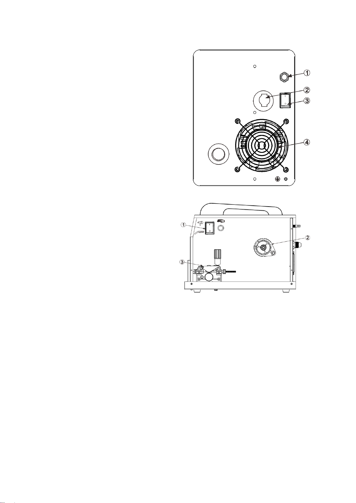
4.2 Rear Panel:
1. Gas inlet: to connect the gas hoses.
2. Power switch: Power ON/OFF
3. Fan: cooling down the fan during the work.
4.3 Internal Panel:
1. Selector switch: to choose torch type for
welding.
2. Wire spool holder: to adopt the welding
wire.
3. Wire feeder: under machine MIG torch
type welding, it will work to feed the wire
to torch. Under spool gun mode, it
doesn’t work.
8
5. INSTALLATION
5.1 Power cord connection:
Connect the machine to the 1phase 220VAC Power supply with leakage protection switch.
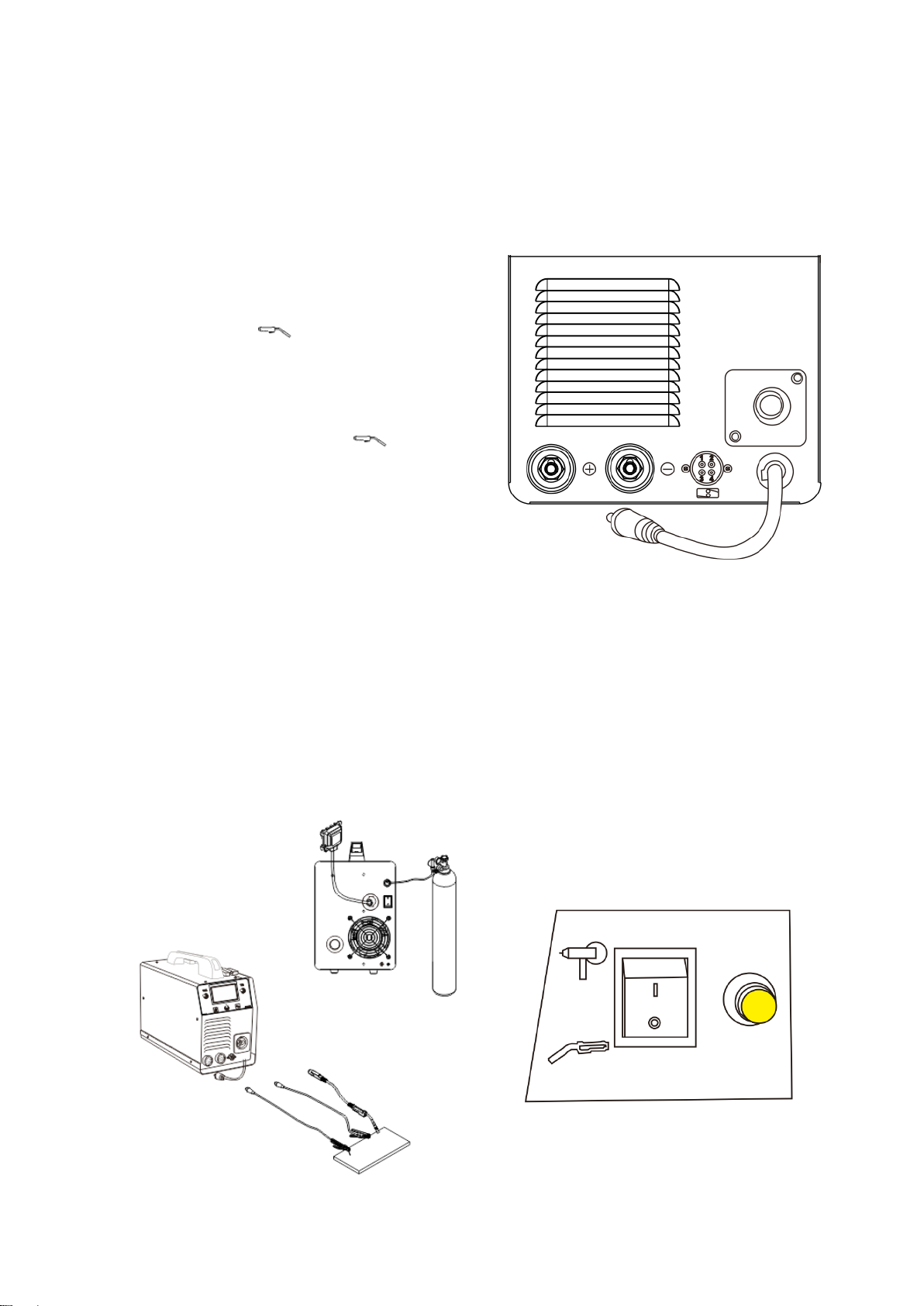
5.2 Output cables connection:
5.2.1 Under MIG with solid wire: welding cable
connector connects “+”, earth clamp connects“-”,
torch connect to “”and fasten it.
5.2.2 Under Flux cored welding with flux wire:
welding cable connector connects “-”, earth clamp
connects“+”, torch connect to“”and fasten
it.
5.2.3 Under MMA mode: welding electrode holder
connects “+”, earth clamp connects“-”.
Notice for spool gun:
When using spool gun, please select the torch switch at “Spool Gun” in the internal panel. Please
choose the spool gun with 24V motor, and it is usually used to weld aluminum or aluminum alloy.
Please use AR 100% as protection gas and welding technics mode set at “SPOOL GUN
ALUMINUM”. Then choose the suitable welding wire size and parameters. For the spool gun
connector on the front panel, “1” “2” is for torch switch, “3””4” is for wire feeder. (“3” is to wire
feeder motor +, and “4” is for wire feeder motor -.)
Figure 1 Figure 2
9
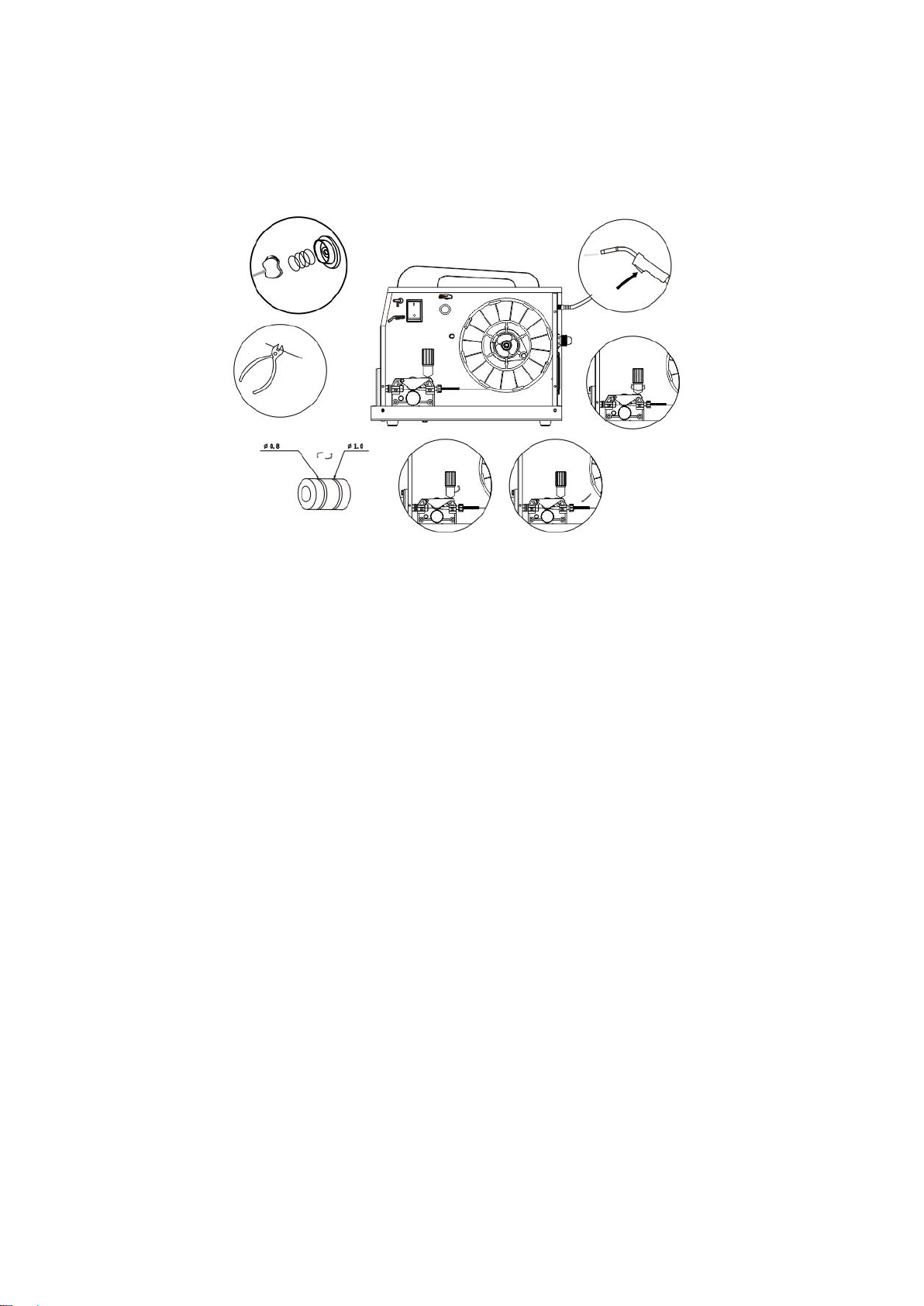
5.3 Filler Wire
5.3.1 Threading the filler wire
1. Open the reel housing by pressing on the opening button and install the wire reel in such a way
that it rotates counter clockwise. You can use either a 5 kg (diameter 200 mm) or l kg (100 mm)
wire reel in the machine.
2. Attach the reel with a reel lock.
3. Unfasten the wire end from the reel, but hold on to it all the time.
4. Straighten the wire end for approximately 20 cm and cut the wire in the straightened location.
5. Open the pressure control lever which then opens the feed gear.
6. Thread the wire through the wire's rear guide to the gun's wire guide.
7. Close the feed gear and fasten it with the pressure control lever. Make sure that the wire runs in
the feed roll groove.
8. Adjust the compression pressure with the pressure control lever no higher than to the middle of
the scale .lf the pressure is too high, it removes metal fragments from the wire surface and may
damage the wire. On the other hand, if the pressure is too low, the feed gear slips and the wire
does not run smoothly.
9. Press the welding gun trigger and wait for the wire to come out.
10. Close the reel housing cover.
CAUTION! When driving the wire in to the gun, do not point the gun at yourself or others or
put, for example, your hand in front of the tip, because the cut wire end is extremely sharp.
Also, do not put your fingers near the feed rolls, because they might get squeezed between
the rolls.
10
5.3.2 Changing the feed roll groove
The feed roll groove is factory set for welding filler wires of 0.8-1.0 mm diameter. The feed roll
groove must be changed if you use 0.6 mm thick filler wire.
1. Open the feed roll from the pressure control lever.
2. Switch the machine on from the main switch.
3. Press the welding gun trigger and drive the feed roll in such a position that its locking screw is
up and can be opened.
4. Switch the power off from the main switch.
5. Open the feed roll locking screw with a 2.0 mm Allen wrench approximately half a turn.
6. Pull the feed roll from its shaft.
7. Turn the feed roll and reinstall it to its shaft all the way to the bottom making sure that the screw
is on the shaft's level.
8. Tighten the feed roll locking screw.
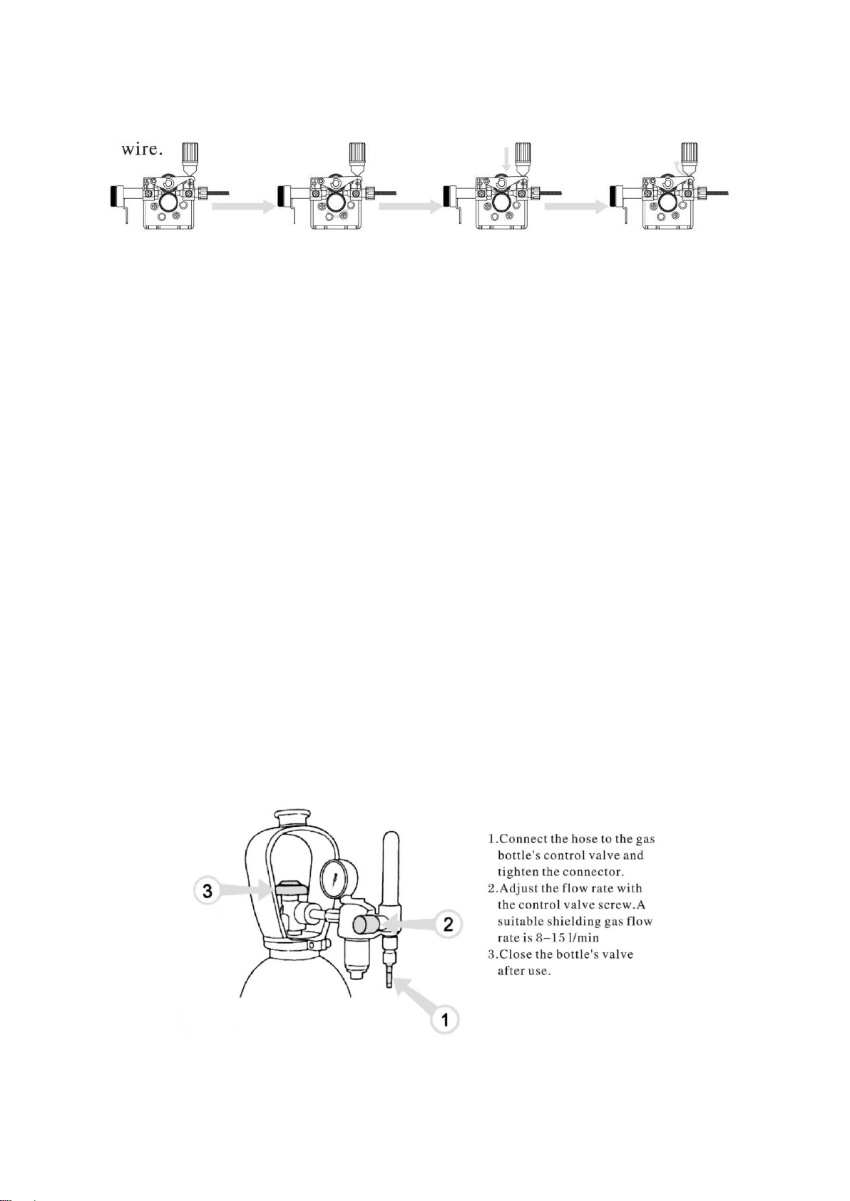
5.4 Shielding gas
The shielding gas used for steel wires is carbon dioxide or a mixture of argon and carbon dioxide
which replaces air in the arc's area. Thickness of the welded sheet and welding power define the
flow rate of the shielding gas.
Connect the bayonet socket of the shielding gas hose to the machine's hose connector and the
hose connector end to the gas bottle's control valve.
NOTE! Use a shielding gas suitable for the material’s welding. Fix the gas bottle securely in
an upright position before installing the control valve.

11
6. OPERATION
6.1 Operation steps:
Please power on the welder, open the gas bottle valve, and adjust the gas pressure to suitable
scale. If not using the spool gun, please select the torch type at “ ” position on the internal
panel.
For the details, please refer to the example below, which is for MIG with mixed gas.
When machine is turn on, please press the central adjusting knob to enter the main menu, after
the program initialization is finished.
Rotate the central adjust knob to select the welding mode
to MIG STEEL C25, and then press the knob to enter this
mode.
The program will guide you the connection for the welding
cable, please do as per request and then press to
continue.
Rotate the knob to select the welding wire diameter and
then press the knob to next step.
Rotate the knob to select the welding material thickness
and then press the knob to enter the pre-welding status.
12
The welding expert system will preset the welding parameters according to the selected wire size
and material thickness. The user can manually fine adjust it as well.
To adjust the welding current, please use the left adjusting knob; and to adjust the welding voltage,
please use the right adjusting knob.
Press the central adjusting knob to enter more parameter setting for MIG, like Run-in WFS,
inductance, spot time, etc.
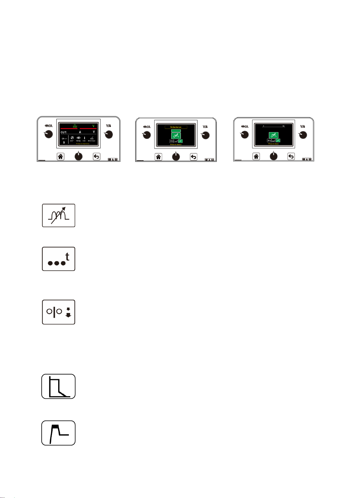
6.2 Options and settings
MIG Options
The inductance option permits adjusting the arc performance, this option can be
used to help with starting and the weld bead profile. A higher inductance setting
provides a softer arc and alower inductance setting provides a crisper arc.
The spot time option permits adjusting the duration of the welding arc. This is used
for tack welds or spot welds. The spot-time option is available in MIG and Flux
cored welding modes.
The run-in option permits adjusting the wire feed speed prior to the arc being
established. A lower run-in speed permits smooth arc starts. After the arc is
established the run-in value is inactive and the set wire feed speed is present. The
run-in option is available in MIG and Flux cored welding modes.
MMA Options
The arc force option permits the user to control the penetration profile. A high arc
force value creates a crisp arc while a low arc force value creates a soft arc. The arc
force option is available in MMA mode.
The hot start option permits adjusting the amperage during arc initialization. After
the arc is established the welding current will decrease to the output current set by
the user. The hot start option is available in MMA mode.

13
Settings
The brightness of the display can be adjusted within the settings option.
The user interface software settings can be reset to the original factory settings.
Please note that all the saved data will be reset to factory setting.
Information regarding the software revision of the user interface and the software
revision of the inverter board is present in the information section.
The language version of the text present in the user interface software.
The units of measure can be chosen by the user. The units can be selected as metric
or English.
AVAILABLE EQUIPMENT OPTIONS
When using spool gun, please select the torch switch at “Spool Gun” in the internal
panel. The spool gun is recommended for aluminum welding.
Scratching TIG option. Please use the TIG torch with scratching arc start.
To use foot pedal under TIG, please connect it to the machine before usage.
7. CAUTION
1. Working Environment
(1) Welding should be carried out in dry environment with its humidity of 90% or less.
(2) The temperature of the working environment should be between -10℃to 40℃.
(3) Avoid welding in the open air unless sheltered from sunlight and rain. Keep it dry anytime
and do not place it on wet ground or in puddles.
(4) Avoid welding in dusty area or environment with corrosive chemical gas.
(5) Gas shielded arc welding should be operated in environment without strong airflow.

14
The following operation requires sufficient professional
knowledge on electric aspect and comprehensive safety
knowledge. Operators should be holders of valid qualification
certificates which can prove their skills and knowledge. Make
sure the input cable of the machine is cut off from the electricity
utility before uncovering the welding machine.
(1) Check periodically whether inner circuit
connection is ok (esp. plugs). Tighten the loose connection. If
there is oxidization, remove it with sandpaper and then
reconnect.
(2) Keep hands, hair and tools away from the moving
parts such as the fan to avoid personal injury or machine
damage.
(3) Clean the dust periodically with dry and clean
compressed air. If welding in environment with heavy smoke
and pollution, the machine should be cleaned daily. The
pressure of compressed air should be at a proper lever lest the
small parts inside the machine be damaged.
2. Safety Tips
Protection circuit is installed in this machine. If the input voltage or the output current is too high or
machine inside temperature over heating inside, the machine will stop automatically. However,
excessive use (e.g. too high voltage) of machine may also damage machine, so please note:
2.1 Ventilation
High current passes when welding is carried out, thus natural ventilation cannot satisfy the
machine's cooling requirement. Maintain good ventilation through the louvers of the machine. The
minimum distance between the machine and any other objects in or near the working area should
be 30cm. Good ventilation is of critical importance for the normal performance and lifespan of the
machine.
2.2 Welding operation is forbidden while the machine is overload. Remember to observe the max
load current at any moment (refer to the corresponding duty cycle). Make sure that the welding
current should not exceed the max load current. Overload could obviously shorten the machine's
lifespan, or even damage the machine.
2.3 Over-voltage is forbidden.
Regarding the power supply voltage range of the machine, please refer to “Main Parameters”
table. This machine is of automatic voltage compensation, which enables the maintaining of the
voltage range within the given range. In case that the input voltage exceeds the stipulated value, it
would possibly damage the components of the machine.
2.4Asudden halt may occur while the machine is of overload status. Under this circumstance, it is
unnecessary to restart the machine. Remain the built-in fan working to lower the temperature
inside the machine.
8. MAINTENANCE
(1) Check periodically whether inner circuit connection is in good condition (esp. plugs).
Tighten the loose connection. If there is oxidization, remove it with sandpaper and then
reconnect.
(2) Keep hands, hair and tools away from the moving parts such as the fan to avoid personal
injury or machine damage.
(3) Clean the dust periodically with dry and clean compressed air. If welding environment
with heavy smoke and pollution, the machine should be cleaned daily. The pressure of
compressed air should be at a proper level in order to avoid the small parts inside the
machine to be damaged.
(4) Avoid rain, water and vapor in filter the machine. If there is, dry it and check the insulation
with equipment (including that between the connections and that between the connection
15
and the enclosure). Only when there are no abnormal phenomena anymore, then the
machine can be used.
(5) Check periodically whether the insulation covers of all cables is in good condition. If there
is any dilapidation, rewrap it or replace it.
(6) Put the machine into the original packing in dry location if it is not to be used for a long
time.
9. DAILY MANITENANCE
•Remove welding spatters from the welding gun's tip and check the condition of the
parts. Change damaged parts to new ones immediately.
•Check that the insulating tips of the welding gun's neck are undamaged and in place.
Change damaged insulation parts to new ones immediately.
•Check the tightness of the welding gun's and earth cable's connections.
•Check the condition of the supply voltage and welding cable and replace faulty
cables.
MAINTENANCE OF THE WIRE FEED MECHANISM
Service the wire feed mechanism at least every time the reel is changed
•Check the wear of the feed roll groove and change the feed roll when necessary.
•Clean the welding gun wire guide with compressed air.
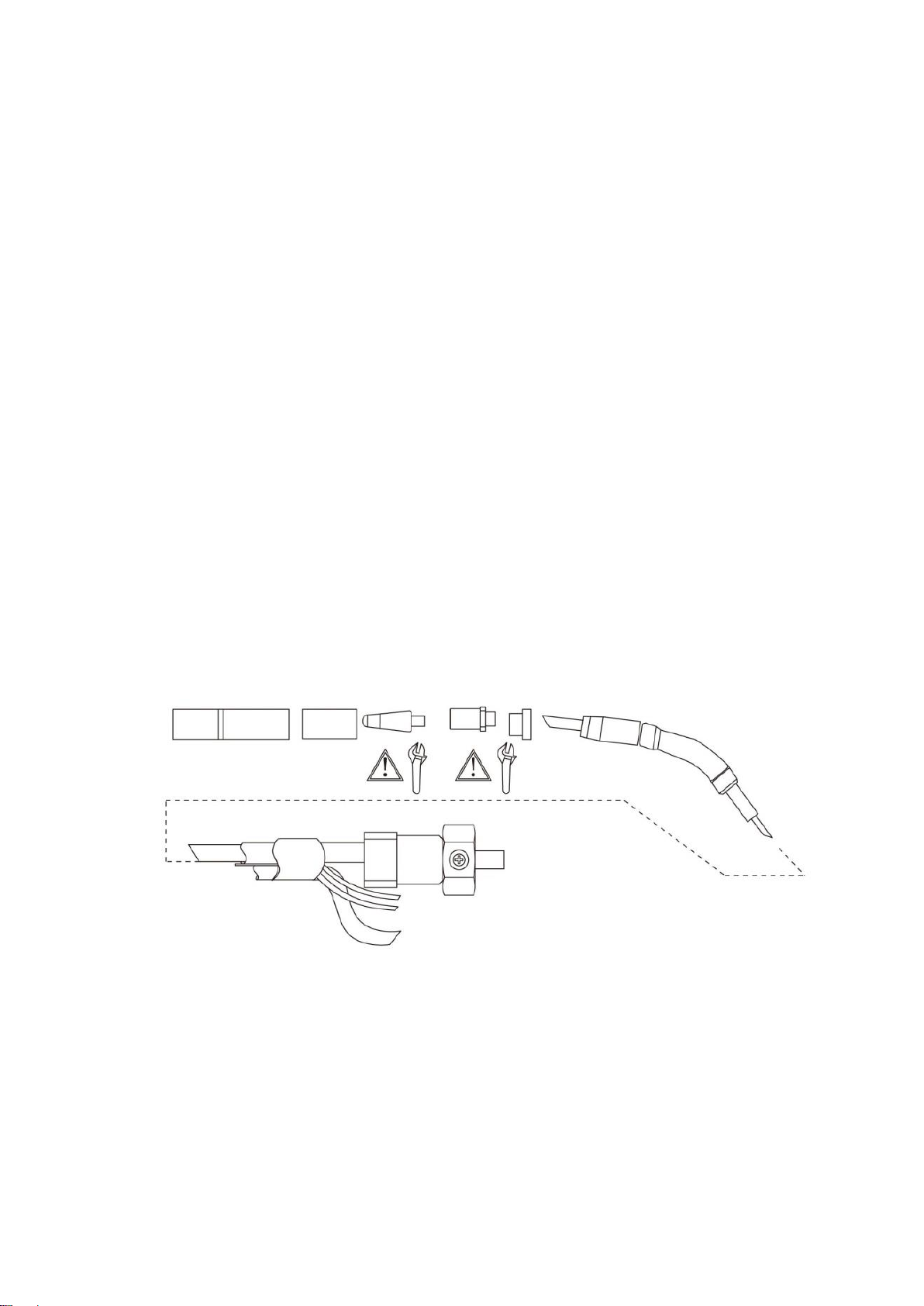
Cleaning the wire guide
Pressure of the feed rolls removes metal dust from the filler wire's surface which then finds its
way to the wire guide. If the wire guide is not clean, it gradually clogs up and causes wire feed
malfunctions. Clean the wire guide in the following manner:
1. Remove the welding gun's gas nozzle, contact tip and contact tip's adapter.
2. With a pneumatic pistol, blow compressed air though the wire guide.
3. Blow the wire feed mechanism and reel housing clean with compressed air.

16
4. Reattach the welding gun's parts, tighten the contact tip and contact tip's adapter to
spanner tightness.
Changing the wire guide
If the wire guide is too worn or totally clogged, change it to a new one according to the
following instructions:
1. Disconnect the welding gun from the machine.
a. Disconnect the cable clamp of the gun's power cable by opening the screws.
b. Disconnect the gun’s power cable from the machine's pole.
c. Disconnect the connector of the trigger conductors from the machine.
d. Open the gun's mounting nut.
e. Extract the gun gently from the machine whereupon all parts come through the front
part's cable hole.
2. Open the mounting nut of the wire guide which exposes the end of the wire guide.
3. Straighten the welding gun's cable and withdraw the wire guide from the gun.
4. Push a new wire guide in to the gun. Make sure that the wire guide enters all the way into
the contact tip's adapter and that there is an O-ring at the machine-end of the guide.
5. Tighten the wire guide in place with the mounting nut.
6. Cut the wire guide 2 mm from the mounting nut and file the sharp edges of the cut round.
7. Reattach the gun in place and tighten the parts to spanner tightness.
17
The following operation requires sufficient professional
knowledge on electric aspect and comprehensive safety
knowledge. Operators should be holders of valid qualification
certificates which can prove their skills and knowledge. Make
sure the input cable of the machine is cut off from the electricity
utility before uncovering the welding machine.
(1) Check periodically whether inner circuit
connection is ok (esp. plugs). Tighten the loose connection. If
there is oxidization, remove it with sandpaper and then
reconnect.
(2) Keep hands, hair and tools away from the moving
parts such as the fan to avoid personal injury or machine
damage.
(3) Clean the dust periodically with dry and clean
compressed air. If welding in environment with heavy smoke
and pollution, the machine should be cleaned daily. The
pressure of compressed air should be at a proper lever lest the
small parts inside the machine be damaged.
(4) Avoid rain, water and vapor infilter the machine. If
there is, dry it and check the insulation with a megger (including
that between the connections and that between the connection
and the case). Only when there is no abnormal phenomena can
welding be continued.
(5) Check periodically whether the insulation skin of all
cables are perfect. If there is any dilapidation, wrap it or replace
it.
(6) Put the machine into the original packing in dry
location if it is not to be used for a long time.
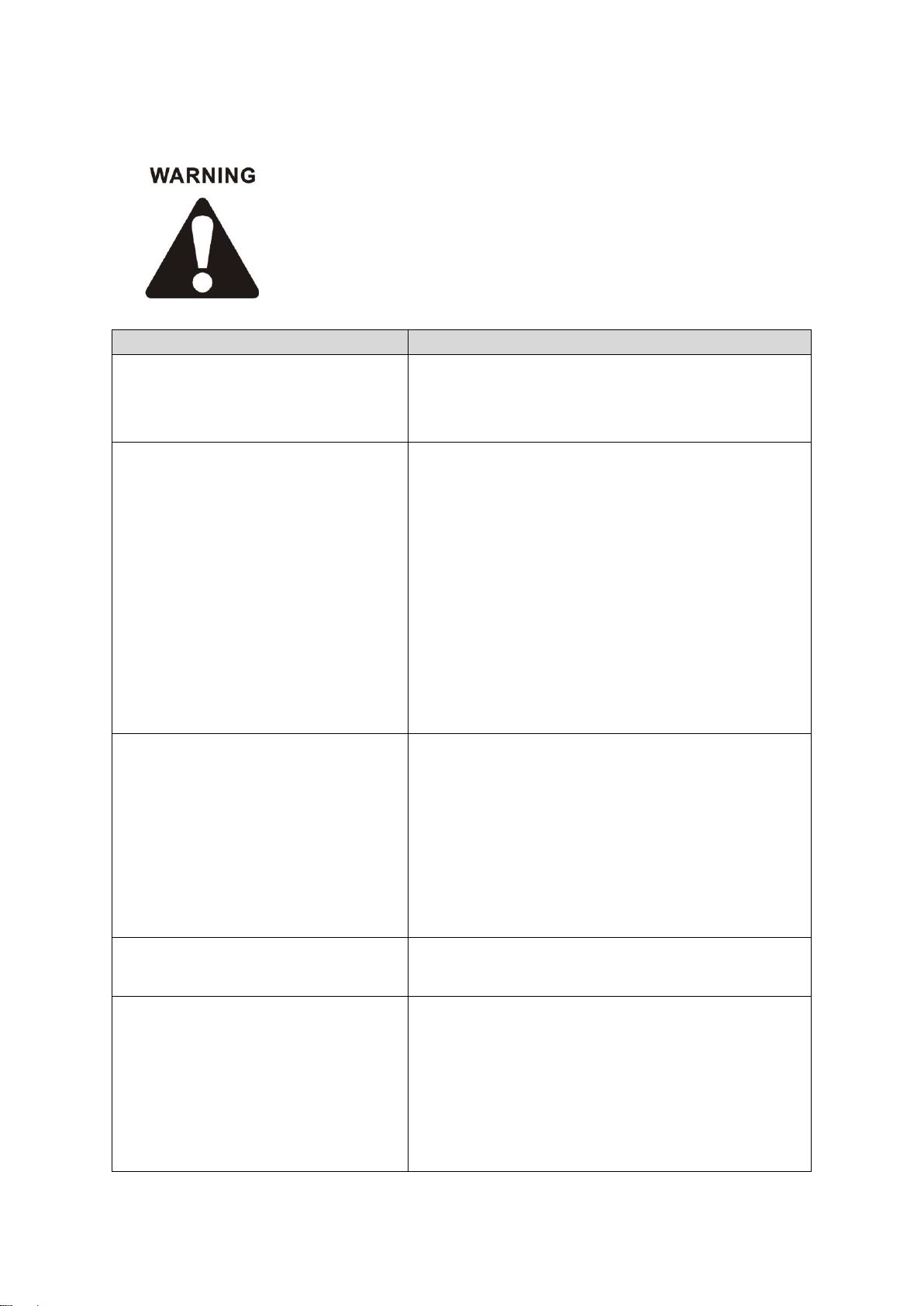
10. TROUBLESHOOTING
PROBLEM
CAUSE
The LCD can’t light up, no wire feeding
during welding, and fan is not working.
•Check if the power switch is on.
•Check if the connected power supply is working.
•Check if the power supply cable is broken.
The LCD is on, fan is working; No wire
feeding during welding.
•Check if the internal wires are well connected.
•Check if any disconnection at the output terminals.
•Check if the control wire or switch on the torch is
broken.
•Check if the control circuit is broken.
•Check if the welding cable is well connected to the
machine.
•Check if the torch type selector is at the right
position for the torch in use.
•If the over-heat light is on, please wait to recover.
The machine output is ok, gas comes
out, but the wire is not feeding
•Check the wire feeding is working or not; if it’s
working, please make sure the wire roller is correct
according to the welding wire.
•Check if the wire tube or nozzle is stuck.
•Make sure the electrode is the right size.
•Check if the torch type selector is at the right
position for the torch in use.
The wire feeding is ok, and welding is
ok, but the gas outlet is abnormal.
•Please check the gas regulator or gas hose.
•Check if the torch is stuck, or any gas leakage.
Welding arc is not stable.
•Please check if the input voltage is correct.
•Please check if the polarity cable connection is
correct.
•Please change the torch head consumables if
they are not in good condition.
•Check if the gas pressure is correct.

18
•Please check if the output cable connection is
loosen.
•Please check if the torch is in good condition.
•Please check if the wire roller size is correct.
•Please check if the electrode size is correct.
Error codes on the LCD.
•The connection between PCB, power control
board and LCD is incorrect. Please restart the
machine.
We are still constantly improving this welder, therefore, some parts of this welder may be
changed in order to achieve the better quality, but the main functions and operations will
not be alternated and changed. Your understanding would be greatly appreciated.

19
11. DIAGRAM
Table of contents
Other IGBT Welding System manuals


Popular Welding System manuals by other brands


Fytech
Fytech FY-92G owner's manual

OEM Tools
OEM Tools 24819 Operating instructions and parts manual

FRONIUS
FRONIUS TSt Series operating instructions

FRONIUS
FRONIUS VR 1500-M operating instructions

Uni-Mig
Uni-Mig VIPER 182 Mk II operating manual

TEAM WELDER
TEAM WELDER MIG drive Synergic puls operating instructions