SIP Weldmate T251P User manual

32
FOR HELP OR ADVISE ON THIS PRODUCT PLEASE CONTACT YOUR DISTRIBUTOR, OR
SIP DIRECTLY ON:
TEL: 01509500400
EMAIL: sales@sip-group.com or technical@sip-group.com
www.sip-group.com
Ref: 010814
Please dispose of packaging for the product in a responsible
manner. It is suitable for recycling. Help to protect the
environment, take the packaging to the local amenity tip
and place into the appropriate recycling bin.
Never dispose of electrical equipment or batteries in with
your domestic waste. If your supplier offers a disposal facili-
ty please use it or alternatively use a recognised re-cycling
agent. This will allow the recycling of raw materials and help
protect the environment.
1
Please read and fully understand the instructions in this manual
before operation. Keep this manual safe for future reference.
05721, 05725, 05741 & 05761
Weldmate
Arc Welder
T141P - T251P

2
31
Declaration of Conformity
We
SIP (Industrial Products) Ltd
Gelders Hall Road
Shepshed
Loughborough
Leicestershire
LE12 9NH
England
As the manufacturer's authorised representative within the EC
declare that the
Weldmate T211P Arc - SIP Part. No. 05721
Weldmate T251P Arc - SIP Part. No. 05725
Weldmate T141P Arc - SIP Part. No. 05741
Weldmate T161P Arc - SIP Part. No. 05761
Conforms to the requirements of the following directive(s), as indicated.
2006/95/EC Low Voltage Directive
2004/108/EC EMC Directive
89/686/EEC Personal Protective Equipment Directive
2008/35/EC RoHS Directive
Signed: …………………………………...
Mr P. Ippaso - Managing Director - SIP (Industrial Products) Ltd
Date: 02/06/2014.
And the relevant harmonised standard(s), including
DECLARATION OF CONFORMITY
EN 60794-1:2012
EN 60794-6:2011
EN 60794-10
EN 379:2003
EN 169:2002
EN 175: 1997

30
PARTS LIST WELDMATE T251P (05725)
Ref. No. Description Sip Part No.
1. Handle WE01-00057
2. Cover WE01-00069
3. Mains lead WE01-00059
4. Cable clamp WE01-00033
5. Rear panel WE01-00034
6. Fan motor WE01-00035
7. Axle WE01-00060
8. Wheel c/w cap WE01-00061
9. Insulation strip WE01-00036
10. Thermostat (transformer) WE01-00037
11. Shunt spindle fork WE01-00038
12. Clip WE01-00039
13. Transformer WE01-00070
14. Shunt WE01-00081
15. Indicator WE01-00042
16. Shunt bracket WE01-00043
17. Hand wheel c/w shaft WE01-00044
18. Chassis WE01-00071
19. Front foot WE01-00064
20. Earth return lead c/w earth clamp WE01-00072
21. Electrode holder lead c/w electrode holder WE01-00073
22. Rotary switch WE01-00067
23. Power indicator WE01-00075
24. Thermal overload indicator WE01-00077
25. Fault indicator WE01-00078
26. Plastic frame WE01-00051
27. Clear window WE01-00052
28. Handle cap WE01-00068
29. Thermostat (fault indicator) WE01-00076
30. Axle clip WE01-00074
N/A. Electrode 02715
N/A. Earth clamp 02735
3
CONTENTS
Page No. Description
4. Safety Symbols Used Throughout This Manual
4. Safety Instructions
11. Electrical Connection
13. Guarantee
13. Contents and Accessories
14. Technical Specification
15. Getting to Know Your Arc Welder
17. Assembly Instructions
18. Operating Instructions
20. Maintenance
21. Troubleshooting
22. Wiring Diagrams
23. Exploded Drawing 05741
24. Parts List 05741
25. Exploded Drawing 05761
26. Parts List 05761
27. Exploded Drawing 05721
28. Parts List 05721
29. Exploded Drawing 05725
30. Parts List 05725
31. Declaration of Conformity

4
When using your arc welder, basic safety precautions should always be followed to
reduce the risk of personal injury and / or damage to the arc welder.
Read all of these instructions before operating the arc welder and save this user man-
ual for future reference.
The arc welder should not be modified or used for any application other than that for
which it was designed.
This arc welder was designed to supply electric current for ARC welding.
If you are unsure of its relative applications do not hesitate to contact us and we will
be more than happy to advise you.
Before each use of the arc welder always check no parts are broken and that no parts
are missing.
Always operate the arc welder safely and correctly.
KNOW YOUR ARC WELDER: Read and understand the owner's manual and labels af-
fixed to the arc welder. Learn its applications and limitations, as well as the potential
hazards specific to it.
KEEP WORK AREA CLEAN AND WELL LIT: Cluttered work benches and dark areas invite
accidents. Floors must not be slippery due to oil, water or sawdust etc.
DO NOT USE THE ARC WELDER IN DANGEROUS ENVIRONMENTS: Do not use the arc
welder in damp or wet locations, or expose it to rain. Provide adequate space sur-
rounding the work area. Do not use in environments with a potentially explosive atmos-
phere.
KEEP CHILDREN AND UNTRAINED PERSONNEL AWAY FROM THE WORK AREA: All visitors
SAFETY SYMBOLS USED THROUGHOUT THIS MANUAL
SAFETY INSTRUCTIONS
IMPORTANT: Please read the following instructions carefully, failure to do
so could lead to serious personal injury and / or damage to the arc
welder.
Danger / Caution: Indicates risk of personal injury and/or the possibility of
damage.
Warning: Risk of electrical injury or damage!
Note: Supplementary information.
29
EXPLODED DRAWING WELDMATE T251P (05725)

28
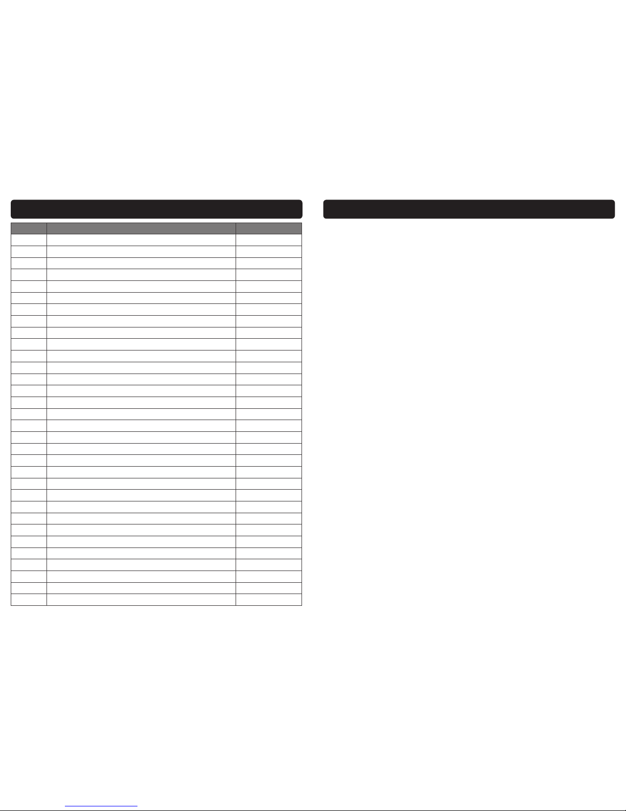
PARTS LIST WELDMATE T211P (05721)
Ref. No. Description Sip Part No.
1. Handle WE01-00057
2. Cover WE01-00058
3. Mains lead WE01-00059
4. Cable clamp WE01-00033
5. Rear panel WE01-00034
6. Fan motor WE01-00035
7. Axle WE01-00060
8. Wheel c/w cap WE01-00061
9. Insulation strip WE01-00036
10. Thermostat (transformer) WE01-00037
11. Shunt spindle fork WE01-00038
12. Clip WE01-00039
13. Transformer WE01-00062
14. Shunt WE01-00081
15. Indicator WE01-00042
16. Shunt bracket WE01-00043
17. Hand wheel c/w shaft WE01-00044
18. Chassis WE01-00063
19. Front foot WE01-00064
20. Earth return lead c/w earth clamp WE01-00065
21. Electrode holder lead c/w electrode holder WE01-00066
22. Rotary switch WE01-00067
23. Power indicator WE01-00075
24. Thermal overload indicator WE01-00077
25. Fault indicator WE01-00078
26. Plastic frame WE01-00051
27. Clear window WE01-00052
28. Handle cap WE01-00068
29. Thermostat (fault indicator) WE01-00076
30. Axle clip WE01-00074
N/A. Electrode 02715
N/A. Earth clamp 02735
5
SAFETY INSTRUCTIONS….cont
should be kept at a safe distance from the work area.
STORE THE ARC WELDER SAFELY WHEN NOT IN USE: The arc welder should be stored in a
dry location and disconnected from the mains supply, and out of the reach of chil-
dren.
USE SAFETY CLOTHING / EQUIPMENT: Use a CE approved welding mask at all times with
the correct shade of filter lens. A fume extractor should be used particularly where
there is little or no ventilation.
PROTECT YOURSELF FROM ELECTRIC SHOCK: When working with the arc welder, avoid
contact with any earthed items (e.g. pipes, radiators, hobs and refrigerators, etc.). It is
advisable wherever possible to use an RCD (residual current device) at the mains
socket.
STAY ALERT: Always watch what you are doing and use common sense. Do not oper-
ate the arc welder when you are tired or under the influence of alcohol or drugs.
DISCONNECT THE ARC WELDER FROM THE MAINS SUPPLY: When not in use and before
servicing.
AVOID UNINTENTIONAL STRIKING: Make sure the switch is in the OFF position before
connecting the arc welder to the mains supply.
NEVER LEAVE THE ARC WELDER CONNECTED WHILST UNATTENDED: Turn the arc welder
off and disconnect it from the mains supply between jobs. Do not leave the arc weld-
er connected to the mains supply if no more welding is to be done.
DO NOT ABUSE THE MAINS LEAD: Never attempt to move the arc welder by the mains
lead or pull it to remove the plug from the mains socket. Keep the mains lead away
from heat, oil and sharp edges. If the mains lead is damaged, it must be replaced by
the manufacturer or its service agent or a similarly qualified person in order to avoid
unwanted hazards. All extension cables must be checked at regular intervals and re-
placed if damaged.
CHECK FOR DAMAGED PARTS: Before every use of the arc welder, any damage found
should be carefully checked to determine that it will operate correctly, safely and per-
form its intended function. Any damaged, split or missing parts that may affect its op-
eration should be correctly repaired or replaced by an authorised service centre un-
less otherwise indicated in this instruction manual.
KEEP ALL PANELS IN PLACE: Never operate the arc welder with any panels removed,
this is extremely dangerous.
MAINTAIN THE ARC WELDER WITH CARE: Keep the earth clamp and electrode holder
clean for the best and safest performance.
USE ONLY RECOMMENDED ACCESSORIES: Consult this user manual, your distributor or
SIP directly for recommended accessories. Follow the instructions that accompany the
accessories. The use of improper accessories may cause hazards and will invalidate
any warranty you may have.
SECURE THE WORK-PIECE: Always use welding clamps to secure the work piece. This
frees up both hands to operate the arc welder correctly.
DO NOT OVERREACH: Keep proper footing and balance at all times.
USE THE RIGHT TOOL: Do not use the arc welder to do a job for which it was not de-

6
SAFETY INSTRUCTIONS….cont
signed.
DO NOT OPERATE THE ARC WELDER IN EXPLOSIVE ATMOSPHERES: Do not use the arc
welder in the presence of flammable liquids, gases, dust or other combustible
sources. Arc welding will create sparks which can ignite the dust or fumes.
DO NOT EXPOSE THE ARC WELDER TO RAIN OR USE IT IN WET CONDITIONS: Water enter-
ing the arc welder will greatly increase the risk of electric shock.
HAVE YOUR ARC WELDER REPAIRED BY A QUALIFIED PERSON: The arc welder is in ac-
cordance with the relevant safety requirements. Repairs should only be carried out by
qualified persons using original spare parts, otherwise this may result in considerable
danger to the user.
Stop operation immediately if you notice anything abnormal.
Always disconnect the plug from the mains supply before cleaning or servicing
etc.
Be alert at all times, especially during repetitive, monotonous operations; Don't
be lulled into a false sense of security.
Use of improper accessories may cause damage to the arc welder and sur-
rounding area as well as increasing the risk of injury.
Do not modify the arc welder to do tasks other than those intended.
To avoid injury, the work-piece should never be held with the bare hands; The
work-piece will become hot during normal welding operations, and stay hot for
a period after the weld is complete.
Appropriate personal protective equipment MUST be worn and MUST be de-
signed to protect against all hazards created. Severe permanent injury can re-
sult from using inappropriate or insufficient protective equipment - Eyes in par-
ticular are at risk.
The work should be clamped firmly whilst welding, If its loose it could result in
personal injury or damage to the machine or item that is being welded.
DO NOT attempt any repairs unless you are a competent electrician or engi-
neer.
Ensure that the machine is connected to the correct supply voltage and pro-
tected by a fuse or circuit breaker of the recommend rating.
Never allow the earth clamp and electrode holder to come into contact with
each other.
27
EXPLODED DRAWING WELDMATE T211P (05721)

26
PARTS LIST WELDMATE T161P (05761)
Ref. No. Description Sip Part No.
1. Handle WE01-00030
2. Cover WE01-00053
3. Mains lead WE01-00054
4. Cable clamp WE01-00033
5. Rear panel WE01-00034
6. Fan motor WE01-00035
7. Insulation strip WE01-00036
8. Thermostat (transformer) WE01-00037
9. Shunt spindle fork WE01-00038
10. Clip WE01-00039
11. Transformer WE01-00055
12. Shunt WE01-00041
13. Indicator WE01-00042
14. Shunt bracket WE01-00043
15. Hand wheel c/w shaft WE01-00044
16. Chassis WE01-00056
17. Earth return lead c/w earth clamp WE01-00046
18. Electrode holder lead c/w electrode holder WE01-00047
19. On/Off switch WE01-00048
20. Thermal overload indicator WE01-00079
21. Fault indicator WE01-00080
22. Plastic frame WE01-00051
23. Clear window WE01-00052
24. Thermostat (fault indicator) WE01-00076
N/A. Electrode holder 02700
N/A. Earth clamp 02735
7
SAFETY INSTRUCTIONS….cont
Keep your body and clothing dry. Never work in a damp area without ade-
quate insulation against electrical shock, stay on a dry duck board, or rubber
mat when dampness or sweat can not be avoided. Sweat, sea water or mois-
ture between the body and an electrically ’hot’ part or grounded metal reduces
the body surface electrical resistance enabling dangerous and possibly lethal
currents to flow through the body.
NEVER allow live metal parts to touch bare skin or any wet clothing, be sure
welding gloves are dry.
Before welding, check for continuity; Be sure the earth clamp is connected to
the work piece as close to the welding areas as possible. Grounds connected
to building frame work or other remote locations from the welding area reduce
efficiency and increase the potential electric shock hazard. Avoid the possibility
of the welding current passing through lifting chains, crane cables or various
electric paths.
Frequently inspect leads for wear, splits, cracks and any other damage. IMME-
DIATELY replace those with worn or damaged insulation to avoid a possibly le-
thal shock from bare leads.
All inflammable materials must be removed from the area.
Have a suitable fire extinguisher available close by.
Causes of fire and explosion are; combustibles reached by the arc, flame, fly-
ing sparks, hot slag or heated material, misuse of compressed gases and cylin-
ders and short circuits.
Flying sparks or falling slag can pass through cracks along pipes, through win-
dows or doors and through walls or floor openings and out of sight of the opera-
tor. Sparks and slag can fly up-to 10 metres.
Keep equipment clean and operable; Free of oil, grease and of metallic parti-
cles (in electrical parts) that can cause short circuits.
If combustibles are in the area. DO NOT weld , move the work if practical to an
area free of combustibles, avoid paint spray rooms, dip tanks, storage areas
and ventilators. If the work can not be moved, then move the combustibles at
least 10 metres away and out of the reach of sparks and heat or protect
against ignition with suitable and snug fitting, fire resistant covers or shields.
Walls touching combustibles on opposite sides should not be welded on, walls,
ceilings and the floor near the work area should be protected by heat resistant
covers or shields.
Openings (concealed or visible) in floors or walls within 10 metres may expose
combustibles to sparks.
Combustibles adjacent to walls, ceilings, roofs or metal partitions can be ignit-
ELECTRIC SHOCK
FIRE

8
SAFETY INSTRUCTIONS….cont
The electric welding arc must not be observed with the naked eye. Always use a
welding mask; Ensure the welding mask is fitted with the correct shade of filter
lens for the welding current level.
Welding gauntlet gloves should be worn to protect the hands from burns, non-
synthetic overalls with buttons at the neck and wrist, or similar clothing should be
worn. Greasy overalls should not be worn. Wear suitable protective footwear.
Always wear correctly rated protective clothing.
Avoid oily or greasy clothing, a spark may ignite them.
Hot metal such as electrode stubs and work pieces should never be handled
without gloves.
First aid facilities and a qualified first aid person should be available for each
shift unless medical facilities are close by for immediate treatment of flash burns
to the eyes and skin.
Flammable hair products should not be used by persons intending to weld.
Warn bystanders not to watch the arc and not to expose themselves to the
welding-arc rays or to hot metal.
Keep children away whilst welding, they may not be aware that looking at an
arc can cause serious eye damage.
Protect other nearby personnel from arc rays and hot sparks with a suitable non-
flammable partition.
GLARE AND BURNS
ed by radiant or conducted heat.
After the work is done, check that the area is free of sparks, glowing embers and
flames.
An empty container that has held combustibles, or that can produce flamma-
ble or toxic vapours when heated, must never be welded, unless the container
has first been cleaned. Consult HSE INDG214, HSG250 and CS15. HSE docu-
ment CS15 includes information on cleaning by thorough steam or solvent/
caustic cleaning followed by purging and inserting with nitrogen, carbon diox-
ide or water filling just below working level.
A container with unknown contents should be treated as if it contained combus-
tibles (see previous paragraph), DO NOT depend on sense of smell or sight to
determine if it is safe to weld.
Hollow items must be vented before welding as they can explode.
Explosive atmosphere; Never weld when the air may contain flammable dust,
gas or liquid vapours (such as petrol).
25
EXPLODED DRAWING WELDMATE T161P (05761)

24
PARTS LIST WELDMATE T141P (05741)
Ref. No. Description Sip Part No.
1. Handle WE01-00030
2. Cover WE01-00031
3. Mains lead WE01-00032
4. Cable clamp WE01-00033
5. Rear panel WE01-00034
6. Fan motor WE01-00035
7. Insulation strip WE01-00036
8. Thermostat (transformer) WE01-00037
9. Shunt spindle fork WE01-00038
10. Clip WE01-00039
11. Transformer WE01-00040
12. Shunt WE01-00041
13. Indicator WE01-00042
14. Shunt bracket WE01-00043
15. Hand wheel c/w shaft WE01-00044
16. Chassis WE01-00045
17. Earth return lead c/w earth clamp WE01-00046
18. Electrode holder lead c/w electrode holder WE01-00047
19. On/Off switch WE01-00048
20. Thermal overload indicator WE01-00049
21. Fault indicator WE01-00050
22. Plastic frame WE01-00051
23. Clear window WE01-00052
24. Thermostat (fault indicator) WE01-00076
N/A. Electrode holder 02700
N/A. Earth clamp 02735
9
SAFETY INSTRUCTIONS….cont
Ventilation must be adequate to remove the smoke and fumes during welding
(see the relevant safety standard for acceptable levels).
Toxic gases may be given off when welding, especially if zinc or cadmium
coated materials are involved, welding should be carried out in a well ventilat-
ed area and the operator should always be alert to fume build-up.
Areas with little or no ventilation should always use a fume extractor.
Vapours of chlorinated solvents can form the toxic gas phosgene when ex-
posed to U.V radiation from an electric arc. All solvents, degreasers and poten-
tial sources of these vapours must be removed from the arc area.
Severe discomfort, illness or death can result from fumes, vapours, heat, oxygen
enrichment or depletion that welding (or cutting) may produce. This will be pre-
vented by adequate ventilation or using a fume extractor. NEVER ventilate with
oxygen.
Lead, cadmium, zinc, mercury, beryllium bearing and similar materials when
welded may produce harmful concentrations of toxic fumes. Adequate ventila-
tion must be provided for every person in the area. The operator should also
wear an air supplied respirator, for beryllium both must be used.
Metals coated with or containing materials that emit toxic fumes should not be
heated unless coating is removed from the work surface. The area should be
well ventilated or the operator should wear an air supplied respirator.
Work in a confined space only while it is being ventilated and if necessary whilst
wearing an air supplied respirator.
Gas leaks in a confined space should be avoided, leaking gas in large quanti-
ties can change oxygen concentration dangerously. DO NOT bring gas cylin-
ders into a confined space.
Leaving a confined space you must shut off the gas supply at the source to
prevent possible accumulation of gases in the space if down stream valves are
left open. Check to be sure that the space is safe before re entering it.
Vapours from chlorinated solvents can be decomposed by the heat of the arc
(or flame) to form phosgene a highly toxic gas and other lung and eye-irritating
products. The ultra violet (radiant) energy of the arc can also decompose tri-
chloroethylene and perchlorethylene vapours to form phosgene. DO NOT WELD
or cut where solvent vapours can be drawn into the welding atmosphere, or
where the radiant energy can penetrate to atmospheres containing even mi-
nute amounts of trichloroethylene or perchlorethylene.
VENTILATION

10
SAFETY INSTRUCTIONS….cont
Some metals and metal composites have the potential to be highly
toxic; always wear a face mask .
When using the arc welder always ensure the operator as well as
those in the area use a welding mask with the correct shade filter
lens.
CAUTION: The warnings and cautions mentioned in this user manual can not
cover all possible conditions and situations that may occur. It must be under-
stood by the operator that common sense and caution are factors which can-
not be built into this product, but must be applied.
23
EXPLODED DRAWING WELDMATE T141P (05741)

22
WIRING DIAGRAM
T141P & T161P
T211P & T251P
11
ELECTRICAL CONNECTION
WARNING! It is the responsibility of the owner and the operator to read, understand
and comply with the following:
You must check all electrical products, before use, to ensure that they are safe.
You must inspect power cables, plugs, sockets and any other connectors for wear or
damage.
You must ensure that the risk of electric shock is minimised by the installation of appro-
priate safety devices; A residual current circuit Breaker (RCCB) should be incorporated
in the main distribution board. We also recommend that a residual current device
(RCD) is used. It is particularly important to use an RCD with portable products that are
plugged into a supply which is not protected by an RCCB. If in any doubt consult a
qualified electrician.
Electrical supply:
The 05741 and 05761 are to be powered from a 230v ~ supply.
The 05721 and 05725 can be powered from a 230v ~ or a 400v~ supply. The power
switch needs to be set to match the mains supply, this is done by moving the stop
screw as shown on the diagram below.
230V 400V
Stop Screw
Connecting to the power supply:
The 05741 is supplied with a 13A plug pre-fitted.
The 05761,05721 and the 05725 are supplied without a plug fitted, they must not be
connected to a standard 13A supply, consult the technical specification table
(page14) for the required rating, if in doubt contact a qualified electrician.
The wires for the plug are coloured in the following way: For 230V operation.
Yellow / green Earth
Blue Neutral
Brown Live

12
Warning: Never connect live or neutral wires to the earth terminal of the
plug. Only fit an approved plug with the correct rated fuse. If in doubt
consult a qualified electrician.
Note: Always make sure the mains supply is of the correct voltage and the
correct fuse protection is used. In the event of replacing the fuse always
replace the fuse with the same value as the original.
Note: If an extension lead is required in order to reach the mains supply;
ensure that this too is rated for the correct voltage and fuse rating.
ELECTRICAL CONNECTION….cont
As the colours of the wires may not correspond with the markings in your plug, pro-
ceed as follows:
The wire which is coloured brown, must be connected to the terminal, which is
marked L or coloured red.
The wire which is coloured blue, must be connected to the terminal marked with N or
coloured black.
The wire which is coloured yellow / green should be connected to the terminal which
is coloured the same or marked with this symbol
Always secure the wires in the plug terminal carefully and tightly. Secure the cable in
the cord grip carefully.
The wires for the plug are coloured in the following way: For 400V operation.
05721 and 05725 only.
Yellow / green Earth
Blue Live/Phase
Brown Live/Phase
The wire which is coloured brown, must be connected to the terminal marked L1.
The wire which is coloured blue, must be connected to the terminal marked L2
The wire which is coloured yellow / green must be connected to the terminal which is
marked with E or this symbol
21
TROUBLESHOOTING
Note: If none of the above solutions work then contact your local distributor
for repair, or contact SIP technical for more advise.

20
MAINTENANCE
If the fault light illuminates you should contact your distributor, or SIP directly to
have the welder checked / repaired.
Clear dust from the machine at regular intervals, if used in a dirty environment
the machine should be cleaned once a month.
Check all connections are clean and tight, if there is any oxidization clean the
connection with a mild abrasive or wire brush.
Check all cables for damaged or degradation to the insulation, replace if any
found.
Check electrode holder and earth clamps condition ensure they clamp tightly,
replace if damaged or loose.
If the machine is not to be used for a long time, store it in the original packing a
dry place.
When the weld is complete simply remove the electrode from the work piece.
Remove any excess weld / slag with the wire brush / hammer.
OPERATING INSTRUCTIONS….cont
IMPORTANT INFORMATION: These units can be set to deliver different output currents at
a duty cycle that is written as a percentage on page 14. This percentage represents
the welding time in a 10 minute cycle, e.g. 60% means that the welding time is 6
minutes and the rest time is 4 minutes. If a unit is used beyond its duty cycle the tem-
peratures of some components might become too high due to over use; The internal
thermal protector will then prevent the unit from operating. Its Intervention is Indicated
by a yellow light on the front panel, If this happens leave the machine switched on
with the fan running and allow It to cool down. The transformer thermal protector will re
-set automatically after a short period of time when the components have cooled
you will be able to restart welding.
13
Guarantee:
These SIP arc welders are covered by a 12 month parts and labour warranty covering
failure due to manufacturers defects. This does not cover failure due to misuse or op-
erating the arc welder outside the scope of this manual - any claims deemed to be
outside the scope of the warranty may be subject to charges Including, but not lim-
ited to parts, labour and carriage costs, failure to regularly clean your arc welder will
shorten its working life and reduce performance.
The warranty does not cover consumable items such as electrode holders & clamps,
etc.
GUARANTEE
Note: Proof of purchase will be required before any warranty can be hon-
oured.
CONTENTS AND ACCESSORIES
Note: If any of the above are missing or damaged, contact your distributor
immediately.
A B C D E
Ref. No. Description
A. Arc Welder
B. Welding Mask & Wire Brush
C. Handle (T141P & T161P)
D. Handle & Wheel Kit (T211P & T251P)
E. Manual

14
TECHNICAL SPECIFICATION
Note: Only the Weldmate T141P can be operated from a 13A supply.
Model 05741
Weldmate T141P
05761
Weldmate T161P
05721
Weldmate T211P
05725
Weldmate T251P
Input Voltage 230v ~ 50Hz 230v ~ 50Hz 230v / 400v ~ 50hz 230v / 400v ~ 50hz
Input Current 13 amps 16 amps 20A / 10A 20A / 10A
OCV 48v 50v 50v 50v
Output Current Range (Amps) 40 - 140 (Peak) 45 - 160 (Peak) 60 - 180 (Peak) 85 - 250 (Peak)
Welding Voltage 19.6v - 22.6v 19.8v - 23.6v 20.4v - 25.2v 21.4v - 26v
Weld Thickness 1.5mm - 5mm 1.5mm - 6mm 2.0mm - 8mm 2.0mm - 9mm
Duty Cycle 115 amps @ 10% 140 amps @ 10% 180 amps @ 10% 200 amps @ 10%
Power Factor 0.6 0.6 0.6 0.6
Efficiency 42% 42% 46% 45%
Insulation Class F F F F
Protection IP21S IP21S IP21S IP21S
Net Weight 15Kg 16.5Kg 20.7Kg 22.6Kg
Note: Operation of the Weldmate T161P, T211P and T251P from a 13A sup-
ply will invalidate the warranty.
19
OPERATING INSTRUCTIONS….cont
The welder should be set to either a specific current or to match the electrode size.
The current control is operated by rotating the large knob on the front of the welder;
Rotate the knob clockwise to increase the current and anticlockwise to reduce the
current. The current setting can the checked by looking at the indicator through the
viewing window on the top of the welder and comparing it with the printed scales.
Once the control is set do a short weld and check for correct fusion.
POWER CONTROL
Current
Electrode size
Fit the required electrode securely into the electrode holder.
Switch the welder on.
Place the face mask over your face.
Clean the area to be welded, and the earthing point of all rust, paint and con-
taminants etc.
Place the earth clamp on to a cleaned area of the work piece.
Connect the welder to the electrical supply but do not switch on.
Note: Be aware that the electrode is now live, simply by touching any part
of the work piece will create a spark.
Bring the electrode into contact with the work piece using a light tapping action
and withdrawing to create a gap of 1.5 mm –3.0 mm.
When the arc is created, proceed steadily in one direction keeping the gap
between the electrode and the work piece constant.
WELDING
PREPARATION FOR WELDING
Caution: Ensure all protective equipment is worn and bystanders are not in
the vicinity.

18
OPERATING INSTRUCTIONS
There are no hard and fast rules by which a particular gauge of electrode is selected,
usually this is determined by the type of welding required and the thickness of the work
piece e.g. a butt weld in 1.5mm (1/16”) . sheet metal can be done by a 1.6mm or
2.0mm electrode, the difference being that the 2.0mm electrode will do the job
more quickly.
The table below gives a guide as to which electrode is most suitable according to the
material thickness. This table is only a guide, and values given are a indication only.
These welding current values are for the E6013 electrodes, for other types of electrode
consult their data sheet.
FITTING THE WHEEL KIT & FRONT FOOT
ASSEMBLY INSTRUCTIONS….cont
WELDMATE T211P & T251P
Fit a circlip over the slot at one end of the axle and slide a wheel from the op-
posite end the axle so that it hits the circlip.
Slide the axle all the way through the pre-drilled holes on the rear of the cover.
Slide the remaining wheel on and secure with the other circlip.
Push the wheel caps onto both wheels.
Place the welder on its side, and use the three screws to attach the front foot.
Electrode Size mm Material Thickness mm Welding Current (A)
1.6 1 - 1.6 25 - 40
2.0 1.6 - 2.6 40 - 70
2.5 2.6 - 4.0 60 - 100
3.25 3.0 - 5.0 80 - 130
4.0 5.0 - 7.0 130 - 170
Note: The above is a guide only; always try a short weld test at the setting
selected. It is normal to make minor adjustments to achieve the required
weld.
Note: The Weldmate T141P and T161P do not come with a wheel kit, and
can not be fitted with one.
15
GETTING TO KNOW YOUR ARC WELDER T141 & T161
1 3
6
4
2
7
10
9
Rear View
11
12
8
Ref. No. Description Ref. No. Description
1. Power Switch 7. Earth Return Lead
2. Thermal Overload Indicator 8. Electrode Holder Lead
3. Fault Indicator 9. Electrode Holder
4. Carrying Handle 10. Current Control Knob
5. Output Scale 11. Cooling Fan Grill
6. Earth Clamp 12. Mains Lead
5

16
GETTING TO KNOW YOUR ARC WELDER T211 & T251
Ref. No. Description Ref. No. Description
1. Power Indicator 8. Earth Return Lead
2. Handle 9. Electrode Holder Lead
3. Thermal Overload Indicator 10. Electrode Holder
4. Output Scale 11. Current Control Knob
5. Fault Indicator 12. Power / Voltage Switch
6. Wheel 13. Cooling Fan Grill
7. Earth Clamp 14. Mains Lead
Rear View
13
14
1
2
3 4
5
6
7
8
9
10
11
12
17
ASSEMBLY INSTRUCTIONS
WELDING MASK
Locate the welding mask, handle and filter lens (above, left).
Slide the filter lens all the way down between the two lens holders on the rear of
the shield (above, middle).
Push the handle through the two slots on the bottom of the welding mask , once
through push the handle up until the pin slots in to the hole on the mask.
The welding mask does not provide unlimited body protection.
Use the welding mask only for eye and face protection from sparks, spatters
and harmful rays from the arc welder.
The filter lens is not suitable for any other application or process.
To ensure your safety, we suggest using impact resistant flash goggles designed
for eye protection when using this welding mask.
Inspect the mask frequently, if damaged in any way DO NOT use until the dam-
aged parts have been replaced.
FITTING THE HANDLE
WELDMATE T141P & T161P
Slide the handle into the slot at the rear of the cover.
Use the screw supplied to secure it tightly to the cover.
WELDMATE T211P & T251P
Place the metal handle over the two holes on top of the cover.
Secure using both bolts & washers.
This manual suits for next models
1
Table of contents
Other SIP Welding System manuals
Popular Welding System manuals by other brands

Lincoln Electric
Lincoln Electric IDEALARC DC-1000 Operator's manual

Miller
Miller Auto-Axcess 300 DI owner's manual

ESAB
ESAB Origo Mag C140 instruction manual

Lincoln Electric
Lincoln Electric INVERTEC IM904 Operator's manual

ESAB
ESAB Caddy Tig 2200iw instruction manual

WIA
WIA WELDMATIC 180 Operator's manual