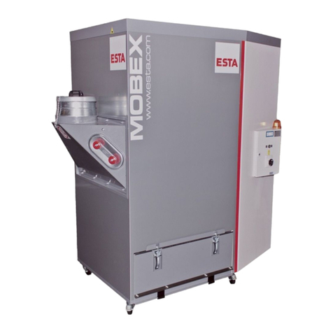
Esta MOBEX F-BIA W3 User manual

Operating manual
MOBEX F- BIA W3
MOBEX F-28 BIA W3 (Order No.: 09820) Raw gas inlet left
MOBEX F-56 BIA W3 (Order No.: 09821) Raw gas inlet left
MOBEX F-28 BIA W3 (Order No.: 09822) Raw gas inlet right
MOBEX F-56 BIA W3 (Order No.: 09823) Raw gas inlet right
Do not use this device unless you have
read the user manual and understand it.
Translation of the original operating manual
09820-08-00

2 MOBEX F- BIA W3 09820-52-00
Warnings and safety instructions
Electrical current hazard
Note
Reference to ESTA customer service
Reference to legal regulations

09820-52-00 MOBEX F- BIA W3 3
Contents
Contents.................................................................................................................................3
1.
General safety notes.......................................................................................................4
2.
Preventing mechanical hazards.....................................................................................6
3.
Preventing electrical hazards.........................................................................................6
4.
Preventing dust hazards.................................................................................................6
5.
Intended use ....................................................................................................................7
6.
Technical data and description......................................................................................8
6.1 Technical data.............................................................................................................8
6.2 Functional description..................................................................................................9
7.
Delivery and commissioning........................................................................................10
7.1 Delivery and transport ...............................................................................................10
7.2 Commissioning..........................................................................................................10
8.
Maintenance and troubleshooting...............................................................................13
8.1 Maintenance instructions...........................................................................................13
8.2 Inspection and maintenance intervals .......................................................................14
8.3 Troubleshooting.........................................................................................................15
9.
Monitoring the minimum airflow volume.....................................................................17
10.
Cleaning.........................................................................................................................17
10.1 Jet filter cleaning......................................................................................................17
10.2 Replacing the filter...................................................................................................18
10.3 Cleaning the demisting mat.....................................................................................20
11.
Disposal .........................................................................................................................21
11.1 Disposing of collected dust materials ......................................................................21
11.2 Disposing of the welding fume exhaust device........................................................21
12.
Optional equipment.......................................................................................................22
13.
Device diagram..............................................................................................................23
14.
Declaration of conformity.............................................................................................24
Notes.....................................................................................................................................25
Notes.....................................................................................................................................26
Notes.....................................................................................................................................27

4 MOBEX F- BIA W3 09820-52-00
1. General safety notes
Before operation, all persons who are to use the welding fume exhaust device or
perform maintenance on it must be provided with information, instructions and
training in using the device and on the substances for which it is to be used,
including the procedure for safe disposal of the collected material. Responsibilities
must be clearly established for the following:
•Installation
•Start-up
•Operation
•Maintenance and repair
The device must be used only by persons who have been instructed in its
handling and are explicitly authorized to use it.
Always keep the operating manual at the place where the welding fume exhaust
device is being used, so that it can be seen by personnel at all times.
The welding fume exhaust device is intended only for dry cleaning and must not
be used or stored outdoors or under wet conditions.
Only original ESTA replacement parts must be used; use of other products will
void the warranty.
During exhaust, the volume flow returned from the welding fume exhaust device
into the room must be no more than 50% of incoming air. With free room
ventilation, the incoming airflow must equal the room volume every hour. This
means that the rate of air replacement must be once per hour.
Incoming air flow [m³/h] = room volume [m³] ∗air replacement rate [1/h]
Example:
When the welding fume exhaust device is operating at the nominal airflow volume
of 1,060 m³/h the same volume of fresh air must therefore be fed in. This occurs
with natural ventilation if the volume of the work room is 1,060 m³ (e.g., 353 m²
surface with a 3 m ceiling height).
No liquids, aggressive gases, easily flammable materials or glowing particles
(such as hot embers) may be aspirated. For example, it is prohibited to use the
welding fume exhaust device in painting operations. It is forbidden to exhaust
processing machines with active ignition sparks or hot embers.

09820-52-00 MOBEX F- BIA W3 5
Installation and operation in dust-explosive or gas-explosive areas is forbidden.
Make sure that the power cable does not become damaged by being run over,
compressed, pulled, etc.
The power cable must be examined regularly for signs of damage or ageing.
The device must not be used if damage to the power cable is determined.
The power cable and plug must be replaced only by an appropriately trained
electrical specialist.
For the power supply and the device’s power cords, only original replacement
parts must be used. This guarantees that they are spray-proof according to
applicable standards and have the necessary mechanical strength.
The power cord must be plugged in only after the welding fume exhaust device
has been successfully set up at its place of use. For this a 16-amp CEE wall
socket (MOBEX F-28) with a 16-amp support fuse, or a 32-amp CEE wall socket
(MOBEX F-56) with a 20-amp support fuse, must be in place.
After use, before moving the devices to another site and before cleaning,
maintenance, or replacement or removal of movable parts, the device must be
unplugged and the compressed air disconnected.
From its first use, the device contains toxic dust. Emptying and
maintenance processes, including removal or emptying of the dust
collection container, must be performed by expert personnel who are
wearing appropriate protective gear. The welding fume exhaust device must
not be operated without the complete filtration system!
According to wor
k equipment user directives 89/655/EWG and TRGS 560,
safety devices for prevention or removal of hazards must be regularly
maintained and regularly inspected by an expert for safe, flawless operation.

6 MOBEX F- BIA W3 09820-52-00
In all emergencies, the device must be disconnect
ed from the power supply
immediately, the device turned off at the emergency switch, and the plug
pulled immediately. If there is a fire, the fire department is to be alerted
immediately, and the fire must be contained by appropriate means.
2. Preventing mechanical hazards
All movable machine parts driven by electric motors must be covered by fixed,
securely fastened protective covers that can be removed only with tools.
Residual risk:
If a covering that can only be unfastened with a tool is removed, there is risk
of injury if the machine is running.
3. Preventing electrical hazards
All electrical parts must be covered by fixed, securely fastened protective covers
that can be removed only with tools. The device complies with Protection Class I
according to EN 60 335.
Residual risk:
If a covering that can only be unfastened with a tool is removed, a hazard is
posed by electric current.
4. Preventing dust hazards
When removing the dust collection container, it is possible to inhale dust.
Following the instructions in the “Disposal” section will minimize this hazard.
When transporting the device, close the intake port securely to prevent dust from
escaping.

09820-52-00 MOBEX F- BIA W3 7
5. Intended use
The welding fume exhaust device has been manufactured according to the state
of the art and in compliance with safety regulations. It is suitable for commercial
use, such as in industrial firms and workshops, for separation of dry, non-
flammable welding fumes.
The welding fume exhaust device corresponds to welding fume exhaust class W3
and is therefore suitable for separation of smoke from steels with an alloy content
such as >30% of nickel and chrome.
Aspiration of welding fumes is not permissible with welding of oil-moistened parts.
The welding fume exhaust device must not be used or stored outdoors or under
wet conditions.
Other applications are considered unintended use. ESTA is not liable for damages
due to unintended use!
The manufacturer sets up the welding fume exhaust device according to the
operator’s information.
For optimal welding fume detection, the capture element must be tracked by using
thermally induced welding fume movement.
Make sure that the welding current return line between the work piece and the
welding machine has a low resistance and that connections between the work
piece and the welding fume separator are avoided, so that the welding current
cannot flow back through the protective ground wire of the welding fume separator
to the welding machine.

8 MOBEX F- BIA W3 09820-52-00
6. Technical data and description
6.1 Technical data
MOBEX BIA W3 model
F
-
28
F
-
56
Filter type Filter cartridge
Number of filter elements [unit] 2 4
Filter area [m²] 28 56
Drive output kW [kW] 2.2 3.0
Max. vacuum Pa [Pa] 2,150 3,000
Max. volume flow [m³/h] 2,400 4,400
Min. volume flow [m³/h] 1,700 2,650
Dust collection container
(per 50 litres) [unit] 1 2
Intake port
(dia.)
[mm] 200 250
Dimensions [L
x W
x H]
1,592 x
850 x
1,941
2,232 x
850 x
1,941
Environmental conditions [°C] 5≤ϑ≤40
Rel. humidity [%] 30 - 70
N
oise (according to casing
body procedure DIN EN ISO
3744) [dBA] 65 66
Connection voltage [V] 400
Rated current [A] 7 8.5
Circuit breaker [A] 16 16
Nominal frequency [Hz] 50 50
Max. air humidity [%] 60 60
Weight [kg] approx. 420 approx. 570
Production year See model plate.

09820-52-00 MOBEX F- BIA W3 9
6.2 Functional description
Depending on the model, the device is driven by a 2.2 kW or 3 kW three-phase
motor that drives a radial fan. The main switch supplies or cuts off the necessary
power to the device, and the device is turned on and off with the red-green double
push button.
The vacuum created by the fan draws air through the suction hose connected to
the intake port. A permanent filter set up within the filter housing separates the
dust that is in the exhausted air or welding fumes. The purified air is guided back
into the room through the exhaust air port.
With the filter cartridges used, the device is equipped with a vacuum monitor as a
control device for overseeing minimum airflow volume. This monitoring device
measures the vacuum behind the filter. With increased dust soiling of the filters,
the flow resistance increases along with the vacuum behind the filter.
If the value set on the vacuum monitor is reached, the filter cartridges are
automatically cleaned with compressed air. If this does not decrease the vacuum,
a siren sounds. This means that the minimum airflow volume has fallen to the limit
and that the filter must be cleaned immediately. See the “Maintenance” section.
The cleaning frees the filter elements of dust and reconditions them. The dust
collection container underneath the filter catches the dust that is cleared.
For easier removal of the collected material, the dust collection container and its
contents can be detached from the device and removed. The plastic bag inserted
into the container (item No. 06000358) with the magnetic strips (item No.
06002080) is for low-emission removal and disposal of the collected hazardous
material. Disposal must be done in compliance with local regulations.

10 MOBEX F- BIA W3 09820-52-00
7. Delivery and commissioning
7.1 Delivery and transport
Beware of crushing hazard!
Wear safety shoes when transporting the machine!
At delivery, the device is fastened to a pallet. After the protective cover and the
bottom fasteners have been removed, the device can be picked up with a forklift
or crane. The roof sheet has eye hooks at the corners for crane transport.
Transport slots are provided for transport with a forklift. Pay attention to the weight
of the welding fume exhaust device and its centre of gravity during all transport
operations.
Upon delivery, please inspect the welding fume exhaust device for transportation
damage. Damage determined must be reported and documented immediately.
ESTA customer service: +49 (0) 7307 804 - 0
When moving the welding fume exhaust device, make sure the ground can
support it and be driven over.
7.2 Commissioning
Only persons authorized under “General safety instructions” must turn the
device on.
Before setting up the
cable connection between the device and the power
grid, check to make sure the operating voltage shown on the model plate is
the same as that of the grid.
When the device is turned off, the neutral line is not disengaged. The device
is therefore intended only for use in TN networks.

09820-52-00 MOBEX F- BIA W3 11
The welding fume exhaust device must be placed on a level surface as near as
possible to the source of welding fumes. Lock the device’s wheels. The welding
fume exhaust device’s intake port has an interior diameter of 200 mm, 250 mm or
160 mm, depending on the model. Onto it is slid and fastened a suitable suction
hose or spiral seam duct (original ESTA accessories) that has the necessary
safety characteristics.
Connection is made to a suction element (exhaust arm, cutting table, etc.) with a
smaller port diameter by using a suitable adaptor that fits the exhaust hose and is
chosen to fit the port diameter of the capture element.
Jet cleaning
The cleaning equipment for the filter elements requires oil- and water-free
compressed air (max. 4 bar at the compressed air nozzle) at the attached
coupling. The ¼-inch plug nipple can be connected with a DN 7.2 ¼-inch coupling
to the compressed air network. For safety, the connection to the compressed air
network should not be made until the device is at its set-up area.
Welding fume class W3 is achieved with pre-coated filters and the pressure limit
for the compressed air for filter cleaning at 4 bar.
Make sure that when the suction equipment is connected the welding fume
exhaust device is turned on first, and then the welding machine. When switching
off, follow the same procedure in reverse. This is guaranteed by using the optional
equipment (see section 12).
Before the device is used, its operation must be tested.
To start up the welding fume exhaust device, the red-yellow main switch is turned
to the “I” position. This switch also serves as an emergency shut-off and can be
secured with a lock against unintentional activation. Then the device can be
started up by pressing the green button on the double push button. The red button
is for shut-off.
Optionally, the device can be equipped with an additional rotary switch (see
section 12).

12 MOBEX F- BIA W3 09820-52-00
Pay attention to the direction of rotation.
After turning on the device for the first time, check to see that the fan rotor’s
direction of rotation is correct. Meanwhile, also look at the red light on the double
push button. If this lights up after the device is turned on, the direction of rotation
is wrong, and the power supply’s polarity must be reversed. For this purpose, the
CEE plug is equipped with a phase inverter. Using a screwdriver to turn the pole
pin built into the insulated part of the plug changes the fan rotor’s direction of
rotation.
When the direction of rot
ation is wrong, the device gets impermissibly hot,
the airflow volume gets weaker, and the device’s performance suffers. This
can also damage the device.
After connection of the suction hose to the source of welding fumes, first the
welding fume exhaust device is started, and then the welding process. When
switching off, follow the same procedure in reverse.
During operation, the welding fume exhaust device’s location should not be
changed.

09820-52-00 MOBEX F- BIA W3 13
8. Maintenance and troubleshooting
8.1 Maintenance instructions
If the device is not needed in its location of use for a long time, it must be stored in
a dry room. The temperature should not be below 5°C or above 40°C.
Before storing the MOBEX, it must be emptied and cleaned.
If necessary, the device can be cleaned with a damp cloth.
It must never be cleaned with flowing water.
For maintenance by qualified personnel, the device must be opened, cleaned and
inspected at the given locations, as well as possible, without any hazard being
posed to maintenance personnel or to other persons. Proper precautions must be
taken before cleaning and removal of wearing parts. This includes locally filtered
forced-air ventilation in the area in which the device is being maintained, and
proper personal protective gear.
During maintenance or repair work, all soiled objects that can no longer be
adequately cleaned must be disposed of. Such objects must be disposed of in a
dustproof bag in compliance with applicable regulations for disposal of such
refuse.
It is recomm
ended that the operator have maintenance performed once per
year. Depending on the mode of operation, the time intervals could be even
shorter. During maintenance, the entire system is to be tested by a trained
expert for correct operation. A written log is to be kept of the main annual
inspection in the included maintenance book. It must document the date of
inspection, deficiencies determined and the name of the inspector. The date
of the next inspection can be read from the test plate installed on the device.

14 MOBEX F- BIA W3 09820-52-00
8.2
Inspection and maintenance intervals
Regular maintenance consists of 3 intervals:
1.
Daily inspection includes:
By the welding fume exhaust device’s user
Visual inspection
•for damage to the device or its parts
•for mechanical damage to the power cable
•for a full dust collection container (regulations require that the container be
emptied if it is more than 2/3 full)
•whether the demisting mat is dirty. If dirty, it must be cleaned.
2.
Monthly inspection includes:
By expert maintenance personnel
Functional and visual inspection
•for filter leaks (dust trails or deposits on the air outlets)
•to guarantee operation of the minimum airflow volume monitor (siren).
During inspection, the device’s air intake must be closed. If the siren
sounds, the equipment is in order.
3.
The main annual inspection includes:
The last test by ESTA is documented on the device.
In collaboration with the ESTA maintenance service
•
Flow volume measurement
•Vacuum measurement
•Current consumption measurement
•Visual check of filters
•Seal inspection
After the main annual inspection, the device receives a new test plate to document
that maintenance has been performed.
This inspection must be done at least once per year.
The maintenance work must be recorded in writing in the maintenance book
provided. This must make clear the equipment inspected and, if necessary, the
deficiencies found, along with the name of the inspector and the date of the
inspection.
If there is a malfunction, the welding fume exhaust device must be switched off
immediately and the responsible maintenance service notified!

09820-52-00 MOBEX F- BIA W3 15
Maintenance must be performed according to accident prevention
regulations. The device must be disconnected from the electrical power and
from the compressed air network. Even when the compressed air supply is
turned off, the compressed air tank is still under pressure!
To empty the compressed air tank, with the compressed air supply shut off,
confirm the manual cleaning and wait until it is completed.
Get the most from ESTA’s maintenance service!
A maintenance contract ensures a long life and top-notch operation for your
welding fume exhaust device.
We’ll make you a great offer — just call us up:
ESTA maintenance service: +49 (0) 7307 804 - 832
ESTA replacement part service: +49 (0) 7307 804 - 831
8.3 Troubleshooting
If dust escapes or clouds up from the air outlets, if smoke develops or the
fan runs loud, the device must immediately be turned off from the red-yellow
main switch!

16 MOBEX F- BIA W3 09820-52-00
Problem
Possible cause
Possible solution
The housing is too hot Suction medium too hot
Make sure there is a
balanced fresh air supply
Suction too weak Main filter dirty
Suction hose clogged
Clean filter
In a vacuumed area, hold
the hose vertically and
bang it out with a rubber
mallet.
Warning signal for low
suction volume persists
despite filter cleaning.
Filter pores clogged in
main filter Replace filter
Motor protection triggers Fan frequently turned on
and off On devices with potential-
free contact, motor
protection must be reset
manually.
Before opening the switch box, make sure to turn the main switch to the “0”
position and pull the electrical plug! Work in the switch box must be
performed only by an electrical expert or an appropriately trained person.

09820-52-00 MOBEX F- BIA W3 17
9. Monitoring the minimum airflow volume
Capture elements with various exhaust port diameters can be used with this
welding fume exhaust device. In so doing, make sure that the exhausted airflow
volume does not drop below the lower limit. This minimum airflow volume depends
on the capture element’s port diameter. Any Y-sections, reducers, hoses and
tubes necessary for connecting are available from ESTA.
The welding fume exhaust device’s monitoring equipment (pressure controller)
must be adjusted to this minimum airflow volume.
The pressure controller must be adjusted only by an appropriately trained
person in consultation with ESTA. The adjustment is made with a size 6
Allen wrench. After the pressure controller has been set, the device is ready
for operation again.
During operation, if the minimum airflow volume drops below that set on the
pressure controller, even after cleaning, a warning signal sounds. The welding
fume exhaust device must be switched off, and the suction side must be checked
for clogging or for a full dust collection container.
10.Cleaning
If necessary, the device can be cleaned with a damp cloth.
It must never be cleaned with flowing water.
10.1 Jet filter cleaning
Pneumatically operated filter cleaning, so-called jet cleaning, is built into the
MOBEX F-28 and F-56. If the vacuum set at the differential pressure switch is
reached during operation, filter cleaning takes place.
Additionally, the filters can be cleaned manually with the blowers turned off (the
main switch must remain on) by pressing the push button marked “Start cleaning”.
Each filter will now be cleaned twice by a compressed air blast. The manual
cleaning process can be repeated as often as needed. However, cleaning must be
done any time the warning signal sounds.
If fine dust is being exhausted, the filters need to be cleaned more often.

18 MOBEX F- BIA W3 09820-52-00
If the warning signal still immediately sounds again after the device has been
cleaned and started, check the amount of material in the dust collection
equipment. If necessary, empty the container. If the warning signal still sounds,
replace the filter elements.
10.2 Replacing the filter
After an extended operation period, the filter pores can be clogged by extremely
fine dust. Even the cleaning equipment cannot remove this dust. The affected filter
must be replaced with a new one. This work should be done only by a
professional.
The new filter bears item No. 30004315.
If possible, filter replacement must be done when there is no work going on. Used
filters must be discarded in compliance with local regulations.
When removing a used filter, the person performing the work must wear a
particle filter class P3 respirator mask, protective clothing and gloves.

09820-52-00 MOBEX F- BIA W3 19
First disconnect the compressed air supply and manually clean the vessel to
empty it. The door cover is separated by pushing it up from the housing. Remove
the screws from the inspection doors that now become visible. Remove the door
to allow access to the filter unit.
To prevent contact with the filter cartridges, pack them from underneath in plastic
bags. Make sure that the closure at the upper end is as dustproof as possible. If
necessary, close the plastic bag with tape at the upper edge so that it doesn’t slip
downward. Then loosen the nuts on the filter cartridges and remove the earthing
(ground) cable from the screw. By rotating each cartridge clockwise, it can be
removed and enclosed completely in the bag.
Install the new filter by performing the same process in reverse. During
installation, make sure to place a new rubber gasket at the top of each cartridge.

20 MOBEX F- BIA W3 09820-52-00
10.3 Cleaning the demisting mat
A demisting mat is installed in the intake port. This mat is for catching sparks so
that they cannot damage the filter. Because it is possible for the demisting mat to
collect flammable particles, it must be inspected and cleaned regularly by the
user.
Therefore, loosen the fastening screws, including the retaining plate to remove the
demisting mat, and clean it with soapy water. If the demisting mat gets too dirty, it
must be replaced. Running the welding fume exhaust device without the demisting
mat is not permitted.
The new demisting mat bears item No. 01000107.
ESTA maintenance service: +49 (0) 7307 804 - 832
ESTA replacement part service: +49 (0) 7307 804 - 831
This manual suits for next models
6
Table of contents
Other Esta Welding System manuals
Popular Welding System manuals by other brands

LOKERMANN
LOKERMANN GRAND MIG 351 MULTI SYN user manual

Gude
Gude GE 185 F Translation of the original operating instructions

PrimeWeld
PrimeWeld CUT50D owner's manual

WARPP
WARPP INTIG 250 PULSE Operation & maintenance manual

Xcel-Arc
Xcel-Arc RazorWeld Razor TIG320 ACDC operating manual

iWeld
iWeld GORILLA POCKETMIG 185 ALUFLUX user manual