Estate W10121806C User manual

INSTALLATION INSTRUCTIONS
30" (76.2 CM) FREESTANDING GAS RANGES
INSTRUCCIONES DE INSTALACIÓN
ESTUFA AUTÓNOMA A GAS DE 30" (76,2 CM)
W10121806C
Table of Contents/Índice
RANGE SAFETY........................................................................................ 2
INSTALLATION REQUIREMENTS .......................................................... 3
Tools and Parts...................................................................................... 3
Location Requirements.......................................................................... 3
Gas Supply Requirements..................................................................... 5
INSTALLATION INSTRUCTIONS ............................................................ 6
Unpack Range ....................................................................................... 6
Install Anti-Tip Bracket...........................................................................6
Verify Anti-Tip Bracket Location............................................................ 7
Level Range ........................................................................................... 7
Make Gas Connection ........................................................................... 7
Check Operation.................................................................................... 8
Check Operation of Oven/Broil Burner ................................................. 9
Complete Installation ........................................................................... 10
GAS CONVERSIONS.............................................................................. 10
LP Gas Conversion.............................................................................. 10
Pilot and Bypass Screws Conversion ................................................. 12
Complete Conversion .......................................................................... 12
Natural Gas Conversion....................................................................... 12
Pilot and Bypass Screws Conversion ................................................. 14
Complete Conversion .......................................................................... 14
SEGURIDAD DE LA ESTUFA ................................................................ 15
REQUISITOS DE INSTALACIÓN........................................................... 16
Piezas y herramientas.......................................................................... 16
Requisitos de ubicación ...................................................................... 16
Requisitos del suministro de gas ........................................................ 18
INSTRUCCIONES DE INSTALACIÓN................................................... 19
Desempaque la estufa......................................................................... 19
Instalación del soporte anti-vuelco .....................................................19
Verificación de la ubicación del soporte anti-vuelco ..........................20
Nivelación de la estufa......................................................................... 20
Conexión del suministro de gas..........................................................21
Verifique el funcionamiento .................................................................21
Verifique el funcionamiento del quemador de asar/del horno............22
Complete la instalación ....................................................................... 23
CONVERSIONES DE GAS .....................................................................24
Conversión de gas LP ......................................................................... 24
Conversión de tornillos de desvío y piloto .......................................... 25
Complete la conversión....................................................................... 26
Conversión de gas natural................................................................... 26
Conversión de tornillos de desvío y piloto .......................................... 27
Complete la conversión....................................................................... 28
IMPORTANT:
Installer: Leave installation instructions with the homeowner.
Homeowner: Keep installation instructions for future reference.
IMPORTANTE:
Instalador: Deje las instrucciones de instalación con el propietario.
Propietario: Conserve las instrucciones de instalación para referencia futura.

2
RANGE SAFETY
You can be killed or seriously injured if you don't immediately
You can be killed or seriously injured if you don't follow
All safety messages will tell you what the potential hazard is, tell you how to reduce the chance of injury, and tell you what can
happen if the instructions are not followed.
Your safety and the safety of others are very important.
We have provided many important safety messages in this manual and on your appliance. Always read and obey all safety
messages.
This is the safety alert symbol.
This symbol alerts you to potential hazards that can kill or hurt you and others.
All safety messages will follow the safety alert symbol and either the word “DANGER” or “WARNING.”
These words mean:
follow instructions.
instructions.
DANGER
WARNING
WARNING: If the information in this manual is not followed exactly, a fire or explosion
may result causing property damage, personal injury or death.
–Do not store or use gasoline or other flammable vapors and liquids in the vicinity of this
or any other appliance.
–WHAT TO DO IF YOU SMELL GAS:
•Do not try to light any appliance.
•Do not touch any electrical switch.
•Do not use any phone in your building.
•Immediately call your gas supplier from a neighbor's phone. Follow the gas supplier's
instructions.
•If you cannot reach your gas supplier, call the fire department.
–Installation and service must be performed by a qualified installer, service agency or
the gas supplier.
WARNING: Gas leaks cannot always be detected by smell.
Gas suppliers recommend that you use a gas detector approved by UL or CSA.
For more information, contact your gas supplier.
If a gas leak is detected, follow the “What to do if you smell gas” instructions.
In the State of Massachusetts, the following installation instructions apply:
■ Installations and repairs must be performed by a qualified or licensed contractor, plumber, or gasfitter qualified or licensed by
the State of Massachusetts.
■ If using a ball valve, it shall be a T-handle type.
■ A flexible gas connector, when used, must not exceed 3 feet.

3
INSTALLATION REQUIREMENTS
Tools and Parts
Gather the required tools and parts before starting installation.
Read and follow the instructions provided with any tools listed
here.
Tools needed
Parts supplied
Check that all parts are included.
■Anti-tip brackets must be securely mounted to subfloor.
Thickness of flooring may require longer screws to anchor
bracket to subfloor. Longer screws are available from your
local hardware store.
Parts needed
Check local codes and consult gas supplier. Check existing gas
supply. See “Gas Supply Requirements” section.
Location Requirements
IMPORTANT: Observe all governing codes and ordinances. Do
not obstruct flow of combustion and ventilation air.
■It is the installer’s responsibility to comply with installation
clearances specified on the model/serial rating plate. The
model/serial rating plate is located on the oven frame behind
the left side of the broiler door.
■The range should be located for convenient use in the kitchen.
■Recessed installations must provide complete enclosure of
the sides and rear of the range.
■To eliminate the risk of burns or fire by reaching over heated
surface units, cabinet storage space located above the
surface units should be avoided. If cabinet storage is to be
provided, the risk can be reduced by installing a range hood
that projects horizontally a minimum of 5" (12.7 cm) beyond
the bottom of the cabinets.
■All openings in the wall or floor where range is to be installed
must be sealed.
■Do not seal the range to the side cabinets.
■Cabinet opening dimensions that are shown must be used.
Given dimensions are minimum clearances.
■The floor anti-tip bracket must be installed. To install the anti-
tip bracket shipped with the range, see “Install Anti-Tip
Bracket” section.
■Proper gas supply connection must be available. See “Gas
Supply Requirements” section.
■Contact a qualified floor covering installer to check that the
floor covering can withstand at least 200°F (93°C).
■Use an insulated pad or ¼" (0.64 cm) plywood under range if
installing range over carpeting.
IMPORTANT: To avoid damage to your cabinets, check with your
builder or cabinet supplier to make sure that the materials used
will not discolor, delaminate or sustain other damage. This oven
has been designed in accordance with the requirements of UL
and CSA International and complies with the maximum allowable
wood cabinet temperatures of 194°F (90°C).
Mobile Home - Additional Installation Requirements
The installation of this range must conform to the Manufactured
Home Construction and Safety Standard, Title 24 CFR, Part 3280
WARNING
Tip Over Hazard
A child or adult can tip the range and be killed.
Connect anti-tip bracket to rear range foot.
Reconnect the anti-tip bracket, if the range is moved.
Failure to follow these instructions can result in death or serious burns to children and adults.
■Level
■³⁄₈" drive ratchet
■Tape measure
■Flat-blade screwdriver
■Phillips screwdriver
■Hand or electric drill
■Wrench or pliers
■7 mm combination wrench
■Pipe wrench
■¹⁄₈" (3.2 mm) drill bit (for wood floors)
■³⁄₁₆" (4.8 mm) carbide-tipped masonry drill bit (for concrete/
ceramic floors)
■Pipe-joint compound resistant to LP gas
■Noncorrosive leak-detection solution
A. Anti-tip bracket
B. Plastic anchors (2)
C. #10 x ¹⁄₂" screws (2)
B
A
C

4
(formerly the Federal Standard for Mobile Home Construction and
Safety, Title 24, HUD Part 280). When such standard is not
applicable, use the Standard for Manufactured Home
Installations, ANSI A225.1/NFPA 501A or with local codes.
Mobile home installations require:
■When this range is installed in a mobile home, it must be
secured to the floor during transit. Any method of securing the
range is adequate as long as it conforms to the standards
listed above.
Product Dimensions
Freestanding Range
Cabinet Dimensions
Cabinet opening dimensions shown are for 25" (64.0 cm)
countertop depth, 24" (61.0 cm) base cabinet depth and
36" (91.4 cm) countertop height.
If the cabinet depth is greater than 24" (61.0 cm), oven frame must
extend beyond cabinet fronts by ½" (13.0 mm) minimum.
IMPORTANT: If installing a range hood or microwave hood
combination above the range, follow the range hood or
microwave hood combination installation instructions for
dimensional clearances above the cooktop surface.
*NOTE: 24" (61.0 cm) minimum when bottom of wood or metal
cabinet is covered by not less than ¹⁄₄" (0.64 cm) flame retardant
millboard covered with not less than No. 28 MSG sheet steel,
0.015" (0.4 mm) stainless steel, 0.024" (0.6 mm) aluminum or
0.020" (0.5 mm) copper.
30" (76.2 cm) minimum clearance between the top of the cooking
platform and the bottom of an uncovered wood or metal cabinet.
29 7/8" (75.9 cm)
42"
(106.7 cm)
24 1/4"
(61.6 cm)
36"
(91.4 cm)
26 3/4"
(67.9 cm)
A. 18" (45.7 cm) upper side cabinet to countertop
B. 13" (33 cm) max. upper cabinet depth
C. 30" (76.2 cm) min. opening width
D. For minimum clearance to top of cooktop, see NOTE*.
E. 30¹⁄₈" (76.5 cm) min. opening width
F. This shaded area recommended for installation of rigid gas
pipe.
G. 8" (20.3 cm)
H. Grounded outlet
I. 17" (43.2 cm)
J. 4¹⁄₂" (11.4 cm)
K. 2" (5.1 cm)
L. 2" (5.1 cm) min. clearance from both sides of range to side
wall or other combustible material.
A
B
C
D
E
F
G
G
H
I
J
K
K
L
M

5
Gas Supply Requirements
Observe all governing codes and ordinances.
IMPORTANT: This installation must conform with all local codes
and ordinances. In the absence of local codes, installation must
conform with American National Standard, National Fuel Gas
Code ANSI Z223.1 - latest edition or CAN/CGA B149 - latest
edition.
IMPORTANT: Leak testing of the range must be conducted
according to the manufacturer’s instructions.
Type of Gas
Natural gas:
This range is design-certified by CSA International for use with
Natural gas or, after proper conversion, for use with LP gas.
■This range is factory set for use with Natural gas. See “Gas
Conversions” section. The model/serial rating plate located
behind the broiler door on the left-hand side oven door frame
has information on the types of gas that can be used. If the
types of gas listed do not include the type of gas available,
check with the local gas supplier.
LP gas conversion:
Conversion must be done by a qualified service technician.
No attempt shall be made to convert the appliance from the gas
specified on the model/serial rating plate for use with a different
gas without consulting the serving gas supplier. See “Gas
Conversions” section.
Gas Supply Line
■Provide a gas supply line of ¾" (1.9 cm) rigid pipe to the range
location. A smaller size pipe on longer runs may result in
insufficient gas supply. Pipe-joint compounds that resist the
action of LP gas must be used. Do not use TEFLON®† tape.
With LP gas, piping or tubing size can be ½" (1.3 cm)
minimum. Usually, LP gas suppliers determine the size and
materials used in the system.
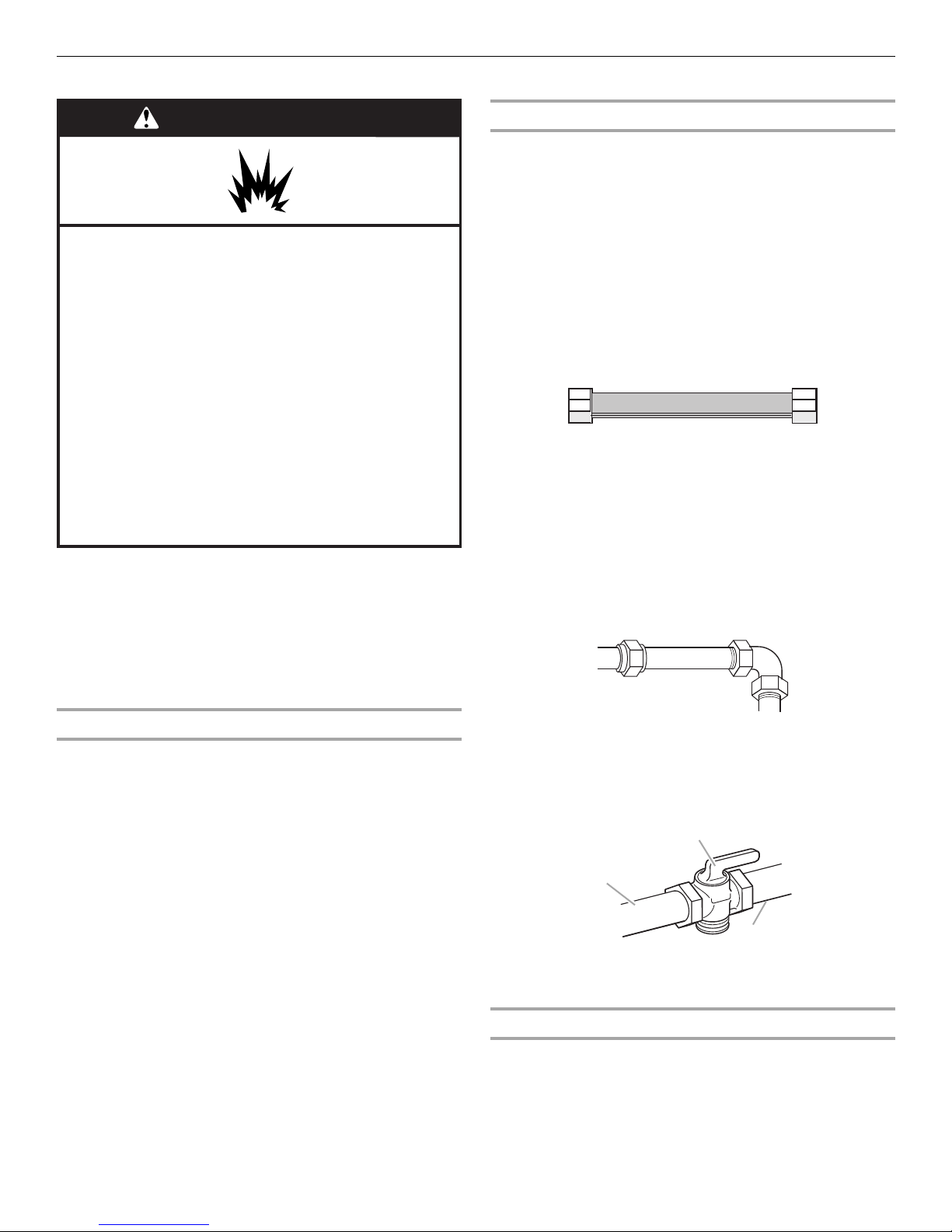
Flexible metal appliance connector:
■If local codes permit, a new CSA design-certified,
4 to 5 ft (122 to 152.4 cm) long, ½" (1.3 cm) or
¾" (1.9 cm) I.D., flexible metal appliance connector may
be used for connecting range to the gas supply line.
■A ½" (1.3 cm) male pipe thread is needed for connection
to the female pipe threads of the inlet to the appliance
pressure regulator.
■Do not kink or damage the flexible metal tubing when
moving the range.
Rigid pipe connection:
The rigid pipe connection requires a combination of pipe
fittings to obtain an in-line connection to the range. The rigid
pipe must be level with the range connection. All strains must
be removed from the supply and fuel lines so range will be
level and in line.
■Must include a shutoff valve:
The supply line must be equipped with a manual shutoff valve.
This valve should be located in the same room but external to
the range. It should be in a location that allows ease of
opening and closing. Do not block access to shutoff valve.
The valve is for turning on or shutting off gas to the range.
Gas Pressure Regulator
The gas pressure regulator supplied with this range must be used.
The inlet pressure to the regulator should be as follows for proper
operation:
Natural gas:
Minimum pressure: 5" WCP
Maximum pressure: 14" WCP
LP gas:
Minimum pressure: 11" WCP
Maximum pressure: 14" WCP
Contact local gas supplier if you are not sure about the inlet
pressure.
Burner Input Requirements
Input ratings shown on the model/serial rating plate are for
elevations up to 2,000 ft (609.6 m).
For elevations above 2,000 ft (609.6 m), ratings are reduced at a
rate of 4% for each 1,000 ft (304.8 m) above sea level (not
applicable for Canada).
Gas Supply Pressure Testing
Gas supply pressure for testing regulator must be at least
1” water column pressure above the manifold pressure shown on
the model/serial rating plate.
WARNING
Explosion Hazard
Use a new CSA International approved gas supply line.
Install a shut-off valve.
Securely tighten all gas connections.
If connected to LP, have a qualified person make sure
gas pressure does not exceed 14" (36 cm) water
column.
Examples of a qualified person include:
licensed heating personnel,
authorized gas company personnel, and
authorized service personnel.
Failure to do so can result in death, explosion, or fire.
A. Gas supply line
B. Shutoff valve “open” position
C. To range
†®TEFLON is a registered trademark of E.I. Du Pont De Nemours and Company.
A
B
C

6
Line pressure testing above ½ psi gauge (14" WCP)
The range and its individual shutoff valve must be disconnected
from the gas supply piping system during any pressure testing of
that system at test pressures in excess of ½ psi (3.5 kPa).
Line pressure testing at ½ psi gauge (14" WCP) or lower
The range must be isolated from the gas supply piping system by
closing its individual manual shutoff valve during any pressure
testing of the gas supply piping system at test pressures equal to
or less than ½ psi (3.5 kPa).
INSTALLATION INSTRUCTIONS
Unpack Range
1. Do not use oven door handle to lift or move the range
2. Remove shipping materials, tape and film from range. Keep
cardboard bottom under range.
3. Remove oven racks and parts package from inside oven.
4. To place range on its back, take 4 cardboard corners from the
carton. Stack one cardboard corner on top of another. Repeat
with the other 2 corners. Place them lengthwise on the floor
behind the range to support the range when it is laid on its
back.
5. Using 2 or more people, firmly grasp the range and gently lay
it on its back on the cardboard corners.
6. Pull cardboard bottom firmly to remove.
7. Use an adjustable wrench to loosen the leveling legs. Adjust
the leveling legs to the correct height. Leveling legs can be
loosened to add up to a maximum of 1" (2.5 cm). A minimum
of ³⁄₁₆" (5.0 mm) is needed to engage the anti-tip bracket.
NOTE: If height adjustment is made when range is standing, tilt
the range back to adjust the front legs, then tilt forward to adjust
the rear legs.
8. Place cardboard or hardboard in front of range. Using 2 or
more people, stand range back up onto cardboard or
hardboard.
Install Anti-Tip Bracket
Contact a qualified floor covering installer for the best procedure
for drilling mounting holes through your type of floor covering.
Before moving range, slide range onto shipping base, cardboard
or hardboard.
1. Remove template from the anti-tip bracket kit (found inside
the oven cavity) or from the back of this manual.
2. Place template on the floor in cabinet opening so that the left
edge is against cabinet and top edge is against rear wall,
molding or cabinet.
3. Tape template into place.
4. If countertop is not flush with cabinet opening edge, align
template with overhang.
If cabinet opening is wider than that specified in the “Location
Requirements” section, adjust template so range will be
centered in cabinet opening.
5. To mount anti-tip bracket to wood floor, drill two ¹⁄₈" (3.2 mm)
holes at the positions marked on the bracket template.
Remove template from floor.
To mount anti-tip bracket to concrete or ceramic floor, use a
³⁄₁₆" (0.48 cm) masonry drill bit to drill 2 holes at the positions
marked on the bracket template. Remove template from floor.
6. Tap plastic anchors into holes with a hammer.
7. Align anti-tip bracket holes with holes in floor. Fasten anti-tip
bracket with screws provided.
Depending on the thickness of your flooring, longer screws
may be necessary to anchor the bracket to the subfloor.
Longer screws are available from your local hardware store.
8. Move range close enough to opening to allow for final gas
connection. Remove shipping base, cardboard or hardboard
from under range.
WARNING
Excessive Weight Hazard
Use two or more people to move and install range.
Failure to do so can result in back or other injury.
WARNING
Tip Over Hazard
A child or adult can tip the range and be killed.
Connect anti-tip bracket to rear range foot.
Reconnect the anti-tip bracket, if the range is moved.
Failure to follow these instructions can result in death
or serious burns to children and adults.

7
9. Open the broiler door. Use a ³⁄₈" drive ratchet to lower the rear
leveling legs one-half turn. Use a wrench or pliers to lower the
front leveling legs one-half turn.
10. Adjust the leveling legs to the correct height. Leveling legs can
be loosened to add up to a maximum of 1" (2.5 cm). A
minimum of ³⁄₁₆" (0.48 cm) is needed to engage the anti-tip
bracket.
11. Move range into its final location making sure rear leveling leg
slides into anti-tip bracket.
12. If installing the range in a mobile home, you must secure the
range to the floor. Any method of securing the range is
adequate as long as it conforms to the standards in the
“Location Requirements” section.
13. Continue installing your range using the following installation
instructions.
Make Gas Connection
1. Remove grates.
2. Lift the cooktop by both front corners until the side support
rods snap into place.
3. Locate gas pressure regulator inside the burner box.
IMPORTANT: Do not remove the gas pressure regulator.
4. All connections should go over and through the burner box
and follow down the range back.
Typical rigid pipe connection
A combination of pipe fittings must be used to connect the range
to the existing gas line. Your connections may be different;
according to the supply line type, size and location.
1. Apply pipe-joint compound made for use with LP gas to all
pipe thread connections.
2. Using a pipe wrench to tighten, connect the gas supply to the
range.
A. Rear leveling leg
B. Front leveling leg
A
A. Rear leveling leg
B Front leveling leg
B
WARNING
Explosion Hazard
Use a new CSA International approved gas supply line.
Install a shut-off valve.
Securely tighten all gas connections.
If connected to LP, have a qualified person make sure
gas pressure does not exceed 14" (36 cm) water
column.
Examples of a qualified person include:
licensed heating personnel,
authorized gas company personnel, and
authorized service personnel.
Failure to do so can result in death, explosion, or fire.
A. Gas pressure regulator
A. Pressure regulator
connection fitting
B. 90° elbow
C. Black iron pipe
D. Union
E. Nipple
F. Manual shutoff valve
G. ½" or ¾" gas pipe
A
G
E
F
C
D
A
B

8
Typical flexible connection
1. Use a combination wrench and pliers to attach the flexible
connector to the adapters. Check that connector is not
kinked.
Complete Connection
1. Open the manual shutoff valve in the gas supply line. The
valve is open when the handle is parallel to the gas pipe.
2. Test all connections by brushing on an approved noncorrosive
leak-detection solution. Bubbles will show a leak. Correct any
leak found.
3. Push back on side support rods and slowly lower the cooktop
until it snaps into place.
4. Place burners, burner caps and grates on the cooktop.
Verify Anti-Tip Bracket Location
1. Make sure the anti-tip bracket is installed
■Look for the anti-tip bracket securely attached to the floor.
■Slide the range back so the rear range foot is under the anti-
tip bracket.
2. If installing the range in a mobile home, you must secure the
range to the floor. Any method of securing the range is
adequate as long as it conforms to the standards in the
“Location Requirements” section.
3. Continue installing your range using the follwing installation
instructions.
Level Range
1. Place rack in oven.
2. Place level on rack and check levelness of range, first side to
side; then front to back.
3. If range is not level, pull range forward until rear leveling leg is
removed from the anti-tip bracket. Use ³⁄₈" drive ratchet and
wrench or pliers to adjust leveling legs up or down until range
is level.
4. Push range back into position.
5. Check that rear leveling leg is engaged in anti-tip bracket.
NOTE: Range must be level for satisfactory baking performance.
Check Operation
To Light Standing Pilot Lights:
Before using the range, the standing pilots must be lit. They will
stay lit after turning off the burners.
1. Make sure all controls are off and the oven and cooktop are
cool.
2. Remove surface grates from the cooktop.
3. Lift the cooktop by both front corners until the side support
rods snap into position.
4. Using a match, light both burner pilot lights.
5. The surface pilot flames should be 0.4" to 0.6"
(1.0 to 1.5 cm) high.
A. Pressure regulator
connection fitting
B. Use pipe-joint compound
C. Adapter
D. Flexible connector
E. Adapter
F. Use pi pe -jo int com poun d
G. Manual shutoff valve
H. ½" or ¾" gas pipe
A. Closed valve
B. Open valve
C
E
G
H
A
D
F
B
A
B
A. Side support rods
A. 0.4" - 0.6" (1.0 - 1.5 cm)
A
A

9
6. If the pilot flame needs adjustment, use a flat blade
screwdriver and turn the adjusting screw until the flame is of
the desired height.
7. Push back on the side support rods and slowly lower the
cooktop until it snaps into position.
8. Push in and turn each surface burner control knob to the “HI”
position. The flame should light with 4 seconds.
9. If surface burners do not ignite, repeat steps 3 to 6.
10. Check each cooktop burner for proper flame. The small inner
cone should have a very distinct blue flame ¼" (0.64 cm) to
½" (1.3 cm) long. The outer cone is not as distinct as the inner
cone.
11. Turn the control knob quickly to the “LO” position after the
burner lights. If the flame goes out, turn the control knob to
the “OFF” position.
12. Check each cooktop burner for proper low flame. The low
flame should be a minimum, steady blue flame. The flame size
should be ¼" to ³⁄₈" (0.64 cm to 0.95 cm) high.
If the low flame needs adjusting:
1. Turn control knob to the “Lo” setting and remove control
knob.
2. Insert a small flat-blade screwdriver into the valve stem. Turn
the valve adjusting screw to obtain the smallest flame that will
not go out when the control of a cold burner is quickly turned
from “HI” to “Lo.” Turn right to decrease flame height. Turn left
to increase flame height. Repeat for other cooktop burners as
needed.
3. Replace control knob.
Check Operation of Oven/Broil Burner
1. Make sure all controls are off and the oven is cool.
2. Open the oven door to remove oven racks and the oven
bottom tray.
3. Remove the fasteners holding the flame spreader. Lift and pull
out the flame spreader.
4. Locate the pilot light on the left-hand side of teh oven burner.
5. Push in oven control knob and hold, then ignite the oven pilot
light with a match.
6. Hold the oven control knob in for 10 seconds to make sure the
pilot will remain lit.
7. If the oven pilot light turns off after releasing the knob, repeat
steps 5 and 6.
8. When the oven pilot remains on, replace the flame spreader,
oven bottome tray and racks.
NOTE: The pilot light will stay lit after turning off the oven. The
oven burner should turn on the next time a temperature is
selected on the oven control knob. If the oven burner does not
turn on, repeat previous steps for lighting oven pilot lights.
9. Open broiler door.
10. Push in and turn the oven control knob to 350°F. The oven
pilot should now be larger with the flame burning against a
small metal bulb. The oven burner should light in
20-40 seconds; this delay is normal. The oven valve requires a
certain time before it will open and allow gas to flow.
11. Check the oven burner for proper flame. The flame should be
½" (1.3 cm) long, with inner cone of bluish-green. The outer
mantle should be dark blue and should be clean and soft in
character. No yellow tips (not enough air), blowing or lifting
(too much air) of flame should occur.
A. Adjusting screw
A. Outer cone
B. Inner cone
A. Valve stem
A
OFF
A
B
A
A. Oven bottom tray
B. Fasteners
C. Flame spreader
A. Oven burner
B. Oven pilot
B
C
A
A
AB
OFF
240
300
350
OVEN TEMP
400
450
500
520
Broil
PUSH TO TURN

10
If the flame needs adjusting:
1. Turn the oven off. Wait for the oven burner to cool down.
2. Open oven door and remove oven racks, oven tray, flame
spreader and set aside.
3. Locate the air shutter near the rear wall of oven and loosen the
shutter screw.
4. Adjust the air shutter.
5. Turn the oven back on and check for proper flame. If the flame
is still not properly adjusted, turn the oven off, wait for the
oven burner to cool down and repeat Step 4 until flame is
properly adjusted.
6. When the flame has been properly adjusted, turn the oven off,
wait for the burner to cool down.
7. Tighten the shutter screw.
8. Reinstall flame spreader and oven tray. Reinstall the oven
racks and close oven door.
Complete Installation
1. Check that all parts are now installed. If there is an extra part,
go back through the steps to see which step was skipped.
2. Check that you have all of your tools.
3. Dispose of/recycle all packaging materials.
4. Check that the range is level. See “Level Range.”
5. Use a mild solution of liquid household cleaner and warm
water to remove waxy residue caused by shipping material.
Dry thoroughly with a soft cloth. For more information, see the
“Range Care” section of the Use and Care Guide.
6. Read the Use and Care Guide.
7. Turn on surface burners and oven. See the Use and Care
Guide for specific instruction on range operation.
If range does not operate, check the following:
■See “Troubleshooting” in the Use and Care Guide.
■When the range has been on for 5 minutes, check for heat. If
the range is cold, turn off the range and check that the gas
supply line shutoff valve is open.
■If the gas supply line shutoff valve is closed, open it, then
repeat the 5-minute test as outlined above.
■If the gas supply line shutoff valve is open, press the
CANCEL button on the oven control panel and contact a
qualified technician.
If you need Assistance or Service:
Please reference the “Assistance or Service” section of the Use
and Care Guide or contact the dealer from whom you purchased
your range.
GAS CONVERSIONS
Gas conversions from Natural gas to LP gas or from LP gas to
Natural gas must be done by a qualified installer.
LP Gas Conversion
A. Oven bottom tray
B. Fasteners
C. Flame spreader
A. Shutter screw
B. Air shutter
B
C
A
A
A
B
WARNING
Explosion Hazard
Use a new CSA International approved gas supply line.
Install a shut-off valve.
Securely tighten all gas connections.
If connected to LP, have a qualified person make sure
gas pressure does not exceed 14" (36 cm) water
column.
Examples of a qualified person include:
licensed heating personnel,
authorized gas company personnel, and
authorized service personnel.
Failure to do so can result in death, explosion, or fire.
WARNING
Tip Over Hazard
A child or adult can tip the range and be killed.
Connect anti-tip bracket to rear range foot.
Reconnect the anti-tip bracket, if the range is moved.
Failure to follow these instructions can result in death
or serious burns to children and adults.

11
To Convert Gas Pressure Regulator
1. Turn manual shutoff valve to the “closed” position.
2. Remove grates.
3. Lift the cooktop by both front corners until the side support
rods snap into position.
4. Locate the gas pressure regulator.
IMPORTANT: Do not remove the gas pressure regulator.
5. With a flat-blade screwdriver, remove the brass cap and flip
the brass cap over so that “LP” is visible.
6. Reinstall the cap and tighten with the flat-blade screwdriver.
To Convert Surface Burners
1. Remove grates from cooktop
2. Lift the cooktop by both front corners until the side support
rods snap into position.
3. Remove the screws that hold each dual burner.
4. Lift each burner and slip it back to remove it.
5. Set them aside.
6. Locate LP gas orifice spuds for top burners in the bag
containing literature included with the range. Four LP gas
spuds are stamped “67.”
7. Remove Natural gas orifice spuds from the valve using a
³⁄₈" (0.95 cm) combination wrench.
8. Install LP gas orifice spuds in the valves.
9. Place the Natural gas orifice spuds in the parts bag for future
use and keep with the bag containing literature.
10. Replace grates.
To Convert Oven Burner
1. Open the oven door and remove oven racks, oven tray, flame
spreader and set aside.
2. Lift oven burner. The orifice spud is behind the oven burner air
shutter.
A. To range
B. Manual shutoff valve “closed“ position
C.Gas supply line
A. Gas pressure regulator
A. Brass cap
A. Cap
A
B
C
A
NAT
A
LP
A
A. Dual burner screws
A. Orifice spuds
B. Valves
A. Air shutter
A
B
A
A

12
3. Locate LP gas orifice spud stamped “56” in the bag
containing literature supplied with the range.
4. Use a ³⁄₈" combination wrench and remove the Natural gas
orifice spud.
5. Install the number “56” LP gas spud.
IMPORTANT: Do not over tighten.
6. Place Natural gas oven burner spud in plastic parts bag along
with Natural gas cooktop burner spuds for future use and
keep with the bag containing literature.
7. Reinstall oven burner.
8. Reinstall oven racks, oven tray and flame spreader.
Pilot and Bypass Screws Conversion
1. Remove control knobs and set aside.
2. Remove upper grates.
3. Lift the cootop by both front corners unti the side support rods
snap into position.
4. Open oven door.
5. Locate the two top fasteners and two bottom fasteners and
remove them using a Phillips head screwdriver.
6. Set the front panel aside and locate the oven thermostat.
7. Locate the LP gas bypass screw in the bag containing
literature included with the range. One LP gas bypass screw is
stamped “48.”
8. Remove the Natural gas bypass screw with a flat-blade
screwdriver, turning counterclockwise.
9. Install the LP gas bypass screw with a flat-blade screwdriver,
turning clockwise.
10. Locate the LP gas pilot screw in the bag containing literature
included with the range. One LP gas pilot screw is stamped
“15.”
11. Remove Natural gas pilot screw with a flat-blade screwdriver,
turning counterclockwise.
12. Install the LP gas pilot screw with a flat-blade screwdriver,
turning clockwise.
13. Replace the front panel and screw bottom and top fasteners
in place.
14. Replace the control knobs. Push back on the side support
rods and slowly lower the cooktop until it snaps into position.
Close the oven door.
Complete Conversion
1. Refer to the “Make Gas Connection” section for properly
connecting the range to the gas supply.
2. Turn the manual shutoff valve in the gas supply line to the
open position.
3. Refer to the “Check Operation” section for proper burner
ingnition, operation and burner flame adjustments.
IMPORTANT: You may have to adjust the “LO” setting for
each cooktop burner.
Checking for proper cooktop and oven burner flames is very
important. The small inner cone should have a very distinct
blue flame ¼" to ½" (0.64 cm to 1.3 cm) long. The outer cone
is not as distinct as the inner cone. LP gas flames have a
slightly yellow tip.
4. Close the broiler door and turn the knob to “OFF.”
5. Refer to the “Complete Installation” section to complete this
procedure.
Natural Gas Conversion
To Convert Gas Pressure Regulator
A. LP oven orifice spud stamped with “56”
A. Top fasteners
B. Bottom fasteners
A. Oven thermostat
A
A
B
A
A. Pilot screw
B. Bypass screw
A
B
WARNING
Tip Over Hazard
A child or adult can tip the range and be killed.
Connect anti-tip bracket to rear range foot.
Reconnect the anti-tip bracket, if the range is moved.
Failure to follow these instructions can result in death
or serious burns to children and adults.

13
1. Turn manual shutoff valve to the “closed” position.
2. Remove grates.
3. Lift the cooktop by both front corners until the side support
rods snap into position.
4. Locate the gas pressure regulator.
IMPORTANT: Do not remove the gas pressure regulator.
5. With a flat-blade screwdriver, remove the brass cap and flip
the brass cap over so that “NAT” is visible.
6. Reinstall the cap and tighten with the flat-blade screwdriver.
To Convert Surface Burners
1. Remove grates from cooktop
2. Lift the cooktop by both front corners until the side support
rods snap into position.
3. Remove the screws that hold each dual burner.
4. Lift each burner and slip it back to remove it.
5. Set them aside.
6. Locate Natural gas orifice spuds for top burners in the bag
containing literature included with the range. Four Natural gas
spuds are stamped “1.42.”
7. Remove the LP gas orifice spuds from the valve using a
³⁄₈" (0.95 cm) combination wrench.
8. Install Natural gas orifice spuds in the valves.
9. Place the LP gas orifice spuds in the parts bag for future use
and keep with the bag containing literature.
10. Push back on the side support rods and slowly lower the
cooktop until it snaps into position.
11. Replace grates.
To Convert Oven Burner
1. Open the oven door and remove oven racks, oven tray, flame
spreader and set aside.
2. Lift oven burner. The orifice spud is behind the oven burner air
shutter.
3. Locate Natural gas orifice spud stamped “48” in the bag
containing literature supplied with the range.
4. Use a ³⁄₈" combination wrench and remove the Natural gas
orifice spud.
5. Install the number “48” Natural gas spud.
IMPORTANT: Do not over tighten.
6. Place LP gas oven burner spud in plastic parts bag along with
Natural gas cooktop burner spuds for future use and keep
with the bag containing literature.
7. Reinstall oven burner.
8. Reinstall oven racks, oven tray and flame spreader.
A. To range
B. Manual shutoff valve “closed” position
C. Gas supply line
A. Brass cap
A. Cap
A. Dual burner screws
A
B
C
LP
A
NAT
A
A
A. Orifice spuds
B. Valves
A. Air shutter
A. LP oven orifice spud stamped with “48”
B
A
A
A

14
Pilot and Bypass Screws Conversion
1. Remove control knobs and set aside.
2. Remove upper grates.
3. Lift the cooktop by both front corners until the side support
rods snap into position.
4. Open oven door.
5. Locate the two top fasteners and two bottom fasteners and
remove them using a Phillips head screwdriver.
6. Set the front panel aside and locate the oven thermostat.
7. Locate the Natural gas bypass screw in the bag containing
literature included with the range. One LP gas bypass screw is
stamped “76.”
8. Remove the LP gas bypass screw with a flat-blade
screwdriver, turning counterclockwise.
9. Install the natrual gas bypass screw with a flat-blade
screwdriver, turning clockwise.
10. Locate the Natural gas pilot screw in the bag containing
literature included with the range. One Natural gas pilot screw
is stamped “94.”
11. Remove LP gas pilot screw with a flat-blade screwdriver,
turning counterclockwise.
12. Install the Natural gas pilot screw with a flat-blade screwdriver,
turning clockwise.
13. Replace the front panel and screw bottom and top fasteners
in place.
14. Replace the control knobs. Push back on the side support
rods and slowly lower the cooktop until it snaps into position.
Close the oven door.
Complete Conversion
1. Refer to the “Make Gas Connection” section for properly
connecting the range to the gas supply.
2. Turn the manual shutoff valve in the gas supply line to the
open position.
3. Refer to the “Check Operation” section for proper burner
ingnition, operation and burner flame adjustments.
IMPORTANT: You may have to adjust the “LO” setting for
each cooktop burner.
Checking for proper cooktop and oven burner flames is very
important. The small inner cone should have a very distinct
blue flame ¼" to ½" (0.64 cm to 1.3 cm) long. The outer cone
is not as distinct as the inner cone. Natural gas flames do not
have yellow tips.
4. Close the broiler door and turn the knob to “OFF.”
5. Refer to the “Complete Installation” section to complete this
procedure.
A. Top fasteners
B. Bottom fasteners
A. Oven thermostat
A
B
A
A. Pilot screw
B. bypass screw
A
B

15
SEGURIDAD DE LA ESTUFA
Si no sigue las instrucciones de inmediato, usted puede
morir o sufrir una lesión grave.
Si no sigue las instrucciones, usted puede morir o sufrir
una lesión grave.
Todos los mensajes de seguridad le dirán el peligro potencial, le dirán cómo reducir las posibilidades de sufrir una lesión y lo que
puede suceder si no se siguen las instrucciones.
Su seguridad y la seguridad de los demás es muy importante.
Hemos incluido muchos mensajes importantes de seguridad en este manual y en su electrodoméstico. Lea y obedezca siempre
todos los mensajes de seguridad.
ADVERTENCIA
PELIGRO
Este es el símbolo de advertencia de seguridad.
Este símbolo le llama la atención sobre peligros potenciales que pueden ocasionar la muerte o una lesión a
usted y a los demás.
Todos los mensajes de seguridad irán a continuación del símbolo de advertencia de seguridad y de la palabra
“PELIGRO” o “ADVERTENCIA”. Estas palabras significan:
ADVERTENCIA: Para su seguridad, la información en este manual debe ser observada
para minimizar el riesgo de incendio o explosión, o para prevenir daños a propiedades,
heridas o la muerte.
–No almacene o use gasolina u otros líquidos y vapores inflamables cerca de este u otro
aparato electrodoméstico.
–PASOS QUE USTED DEBE SEGUIR SI HUELE A GAS:
•No trate de encender ningún aparato electrodoméstico.
•No toque ningún interruptor eléctrico.
•No use ningún teléfono en su casa o edificio.
•Llame inmediatamente a su proveedor de gas desde el teléfono de un vecino.
Siga las instrucciones de su proveedor de gas.
•Si usted no puede comunicarse con su proveedor de gas, llame al departamento
de bomberos.
–La instalación y el servicio deben ser efectuados por un instalador calificado, una
agencia de servicio o por el proveedor de gas.
ADVERTENCIA: Las pérdidas de gas no siempre se pueden detectar por el olfato.
Los proveedores de gas recomiendan que usted use un detector de gas aprobado por UL (Laboratorio de normalización) o
CSA (Asociación canadiense de seguridad).
Para obtener más información, póngase en contacto con su proveedor de gas.
Si se detecta una fuga de gas, siga las instrucciones de “Pasos que usted debe seguir si huele a gas”.

16
REQUISITOS DE INSTALACIÓN
Piezas y herramientas
Reúna las herramientas y piezas necesarias antes de comenzar la
instalación. Lea y siga las instrucciones provistas con cualquiera
de las herramientas enlistadas aquí.
Herramientas necesarias
Piezas suministradas
Verifique que estén todas las piezas.
■Los soportes deben estar montados en el contrapiso
firmemente. Según el espesor del piso, es posible que sea
necesario utilizar tornillos más largos para sujetar el soporte al
contrapiso. Puede conseguir tornillos más largos en su
ferretería local.
Piezas necesarias
Verifique los códigos locales y consulte con el proveedor de gas.
Verifique el suministro de gas existente. Vea la sección
“Requisitos del suministro de gas”.
Requisitos de ubicación
IMPORTANTE: Observe todos los códigos y reglamentos
aplicables. No obstruya el flujo de aire para la combustión y la
ventilación.
■Es la responsabilidad del instalador cumplir con los espacios
de instalación especificados en la placa con la clasificación
de modelo/serie. La placa indicadora de modelo/serie está
ubicada en el marco del horno, detrás del lado izquierdo de la
puerta del asador.
■Deberá colocarse la estufa en un lugar conveniente de la
cocina para su uso.
■Las instalaciones empotradas deberán proveer un recinto
cerrado de los lados y la parte posterior de la estufa.
■Para eliminar el riesgo de quemaduras o incendio al tocar
unidades con la superficie demasiado caliente, deberá
evitarse el uso de armarios de almacenaje encima de las
unidades. Si van a proveerse armarios, puede reducir el riesgo
instalando una capota de ventilación que se proyecte
horizontalmente un mínimo de 5" (12,7 cm) sobresaliendo de
la base de los armarios.
■Deberán sellarse todas las aberturas en la pared o en el piso
en donde se instalará la estufa.
En el estado de Massachusetts se aplican las siguientes instrucciones de instalación:
■ Las instalaciones y reparaciones se deben efectuar por un contratista, plomero o gasista calificado o licenciado por el estado
de Massachusetts.
■ Si se usa una válvula de bola, debe ser un tipo de manigueta T.
■ Si se usa un conector de gas flexible no debe exceder de 3 pies.
Peligro de Vuelco
Un niño o un adulto puede volcar accidentalmente la estufa y resultar muerto.
Conecte el soporte anti-vuelco a la pata trasera de la estufa.
Si traslada de lugar la estufa, vuelva a conectar el soporte anti-vuelco.
No seguir estas instrucciones puede ocasionar la muerte o quemaduras graves en niños y
adultos.
ADVERTENCIA
■Nivel
■Trinquete de accionamiento de ³⁄₈"
■Cinta para medir
■Destornillador de hoja plana
■Destornillador Phillips
■Taladro manual o eléctrico
■Llave de tuerca o pinzas
■Llave de combinación de 7 mm
■Llave para tubos
■Broca de ¹⁄₈" (3,2 mm) (para pisos de madera)
■Broca para albañilería con punta de carburo de ³⁄₁₆" (4,8 mm)
(para pisos de concreto/cerámica)
■Pegamento para tuberías resistente a gas LP
■Solución para detectar fugas, que no sea corrosiva
A. Soporte anti-vuelco
B. Taquetes de plástico (2)
C. Espitas #10 x ½" (2)
B
A
C

17
■No selle la estufa a los armarios laterales.
■Deben usarse las dimensiones de la abertura del armario que
se muestran. Las dimensiones proporcionadas son los
espacios mínimos.
■Debe instalarse el soporte anti-vuelco del piso. Para instalar el
soporte anti-vuelco enviado con la estufa, vea la sección
“Instalación del soporte anti-vuelco”.
■Deberá haber una conexión adecuada del suministro de gas.
Vea la sección “Requisitos del suministro de gas”.
■Póngase en contacto con un instalador calificado de
revestimiento de pisos para cerciorarse de que el
revestimiento del piso puede soportar por lo menos 200°F
(93°C).
■Use una almohadilla aislante o una madera laminada de ¼"
(0,64 cm) debajo de la estufa si va a instalar la estufa sobre
una alfombra.
IMPORTANTE: Para evitar daños a sus armarios, verifique con el
constructor o distribuidor de armarios para asegurarse de que los
materiales que se usen no se descoloren, astillen ni sufran ningún
otro tipo de daño. Este horno ha sido diseñado de acuerdo a los
requisitos de UL y CSA International, y cumple con las
temperaturas máximas permitidas para armarios de madera de
194°F (90°C).
Requisitos de instalación adicionales para las casas
rodantes
La instalación de esta estufa debe ajustarse al Estándar de
seguridad y construcción de casas fabricadas, Título 24 CFR,
Parte 3280 (anteriormente conocido como Estándar federal para
la seguridad y construcción de casas rodantes, Título 24, HUD
Parte 280). Cuando no sea aplicable ese estándar, use el Estándar
para instalaciones en casas fabricadas, ANSI A225.1/NFPA 501A
u obedezca los códigos locales.
Las instalaciones en casas rodantes necesitan:
■Cuando se instale esta estufa en una casa rodante, deberá
asegurarse al piso durante el transporte. Cualquier método de
fijación es adecuado en tanto cumpla con las normas
indicadas arriba.
Medidas del producto
Estufa autónoma
Espacios libres para instalación
Las dimensiones de la abertura del armario que se muestran son
para una profundidad del mostrador de 25" (64,0 cm),
profundidad de la base del armario de 24" (61,0 cm) y una altura
del mostrador de 36" (91,4 cm).
Si la profundidad del armario es mayor de 24" (61,0 cm), deberá
extenderse el marco del horno más allá de los frentes del armario
por un mínimo de ½" (13,0 mm).
IMPORTANTE: Si va a instalar una campana para estufa o una
combinación microondas campana sobre la estufa, siga las
instrucciones de instalación incluidas con la campana para estufa
o la combinación microondas campana para las medidas de
espacio sobre la superficie de cocción.
*NOTA: 24" (61,0 cm) mínimo cuando la base del armario de
madera o de metal esté protegida por cartón retardante a las
llamas de no menos de ¼" (0,64 cm), cubierto de lámina de
acero de no menos de N° 28 MSG, acero inoxidable de 0,015"
(0,4 mm), aluminio de 0,024" (0,6 mm) o cobre de 0,020"
(0,5 mm).
30" (76,2 cm) de espacio mínimo entre la parte superior de la
plataforma de la superficie de cocción y la base de un armario de
madera o metal desprotegido.
29 7/8" (75,9 cm)
42"
(106,7 cm)
24 1/4"
(61,6 cm)
36"
(91,4 cm)
26 3/4"
(67,9 cm)
A. 18" (45,7 cm) del armario lateral superior al mostrador
B. 13" (33 cm) profundidad máxima del armario superior
C. 30" (76,2 cm) ancho mínimo de la abertura
D. Para ver el espacio mínimo hasta la parte superior de la
superficie de cocción, vea la NOTA*.
E. 30¹⁄₈" (76,5 cm) ancho mínimo de la abertura
F. Se recomienda esta área sombreada para la instalación de
la tubería de gas rígida.
G. 8" (20,3 cm)
H. Contacto con conexión a tierra
I. 17" (43,2 cm)
J. 4¹⁄₂" (11,4 cm)
K. 2" (5,1 cm)
L. Espacio mínimo de 2" (5,1 cm) de ambos lados de la estufa
para la pared lateral u otro material combustible.
A
B
C
D
E
F
G
G
H
I
J
K
K
L
M
18
Requisitos del suministro de gas
Observe todos los códigos y reglamentos aplicables.
IMPORTANTE: Esta instalación debe hacerse de acuerdo con
todos los códigos y ordenanzas locales. Si no hay códigos
locales, la instalación deberá hacerse de acuerdo al Código
Nacional Estadounidense (American National Standard), el
Código Nacional de Gas Combustible (National Fuel Gas Code),
ANSI Z223.1- última edición o CAN/CGA B149 - última edición.
IMPORTANTE: La prueba de fugas de la estufa deberá
efectuarse según las instrucciones del fabricante.
Tipo de gas
Gas natural:
El diseño de esta estufa está certificado por CSA International
para gas natural o, después de la conversión apropiada, para
usarse con gas L.P.
■Esta estufa está preparada de fábrica para uso con gas
natural. Vea la sección “Conversiones de gas”. La placa
con el número de modelo/serie, ubicada en el marco, del
lado derecho, detrás del cajón de almacenamiento, tiene
información acerca de los tipos de gas que pueden
usarse. Si la lista de tipos de gas no incluye el tipo de gas
disponible, averigüe con el distribuidor de gas de su
localidad.
Conversión de gas L.P.:
La conversión deberá llevarla a cabo un técnico de servicio
calificado.
No se deberá hacer intento alguno para convertir el aparato
del gas especificado en la placa de clasificación del modelo/
serie para utilizar un gas distinto sin consultar con el
abastecedor de gas. Vea la sección “Conversiones de gas”.
Línea de suministro de gas
■Provea una línea de suministro de gas de tubería rígida de
¾" (1,9 cm) hacia la ubicación de la estufa. Una tubería de
tamaño más pequeño en tendidos más largos puede traer
como consecuencia un suministro de gas insuficiente.
Deben usarse compuestos para uniones de tubería que
sean resistentes a la acción del gas LP. No utilice cinta
TEFLON®. Con el gas LP, el tamaño de la tubería puede
ser de un mínimo de ½" (1,3 cm). Por lo general, los
proveedores de suministro de gas LP determinan el
tamaño y los materiales a usarse en el sistema.
Conector flexible de metal del aparato:
■Si los códigos locales lo permiten, puede usarse un
conector de metal flexible para aparatos nuevo, con
diseño certificado de CSA, de 4 a 5 pies (122 a 152,4 cm)
de largo, diámetro interno de ½" (1,3 cm) ó ¾" (1,9 cm)
para conectar la estufa a la línea de suministro de gas.
■Se necesita una rosca macho para tubería de ½" (1,3 cm) para
conectar las roscas hembra de la entrada al regulador de
presión del aparato.
■No tuerza ni dañe la tubería de metal flexible cuando mueva la
estufa.
Conexión de tubería rígida:
La conexión de tubería rígida requiere una combinación de
accesorios de tubería para obtener una conexión en línea hacia la
estufa. La tubería rígida deberá estar nivelada con la conexión de
la estufa. Deberán quitarse todas las torceduras de las líneas de
suministro y de combustible para que la estufa esté nivelada y
alineada.
■Debe tener una válvula de cierre:
La línea de suministro deberá equiparse con una válvula de
cierre manual. Esta válvula deberá estar ubicada en la misma
habitación pero fuera de la estufa. Deberá estar en una
ubicación que permita un fácil acceso para abrir y cerrar. No
bloquee el acceso a la válvula de cierre. La válvula es para
abrir o cerrar el suministro de gas a la estufa.
Regulador de la presión de gas
Deberá usarse el regulador de la presión de gas suministrado con
esta estufa. Para el funcionamiento adecuado, la presión de
entrada al regulador deberá ser como se indica a continuación:
Gas natural:
Presión mínima: 5" WCP
Presión máxima: 14" WCP
ADVERTENCIA
Peligro de Explosión
Use una línea de suministro de gas nueva con
aprobación de CSA International.
Instale una válvula de cierre.
Apriete firmemente todas las conexiones de gas.
Si se conecta a un suministro de gas LP, la presión no
debe exceder una columna de agua de 36 cm (14") y
debe ser verificada por una persona calificada.
Ejemplos de una persona calificada incluyen:
personal de servicio del sistema de calefacción con
licencia,
personal autorizado de la compañía de gas, y
personal autorizado para dar servicio.
No seguir estas instrucciones puede ocasionar
la muerte, explosión o incendio.
A. Línea de suministro de gas
B. Válvula de cierre en posición “abierta”
C. A la estufa
†®TEFLON es una marca registrada de E.I. Du Pont De Nemours and Company.
A
B
C

19
Gas LP:
Presión mínima: 11" WCP
Presión máxima: 14" WCP
Póngase en contacto con el proveedor de gas de su localidad si
no está seguro acerca de la presión de entrada.
Requisitos de entrada del quemador
Los rangos de entrada que se muestran en la placa de
clasificación del modelo/serie son para elevaciones de hasta
2.000 pies (609,6 m).
Para elevaciones mayores de 2.000 pies (609,6 m), los rangos se
reducen a un flujo de 4 % por cada 1.000 pies (304,8 m) por
encima del nivel del mar (no es aplicable para Canadá).
Prueba de presión del suministro de gas
La presión del suministro de gas para un regulador de prueba
debe ser de al menos 1" de la presión de la columna de agua
sobre la presión del múltiple, que se muestra en la placa
indicadora del modelo/serie.
Prueba de presión de la línea por encima de ½ lb/pulg²
manométrica (presión de la columna de agua de 14 )
La estufa y su válvula de cierre individual deberán ser
desconectadas del sistema de tubería del suministro de gas
durante toda prueba de presión efectuada en dicho sistema a
presiones de prueba mayores de ½ lb/pulg² (3,5 kPa).
Prueba de presión de la línea a ½ lb/pulg² (presión de una
columna de agua de 14") o menor
La estufa deberá aislarse del sistema de tubería del suministro de
gas cerrando la válvula de cierre individual manual durante toda
prueba de presión efectuada en dicho sistema a presiones de
prueba iguales o menores de ½ lb/pulg² (3,5 kPa).
INSTRUCCIONES DE INSTALACIÓN
Desempaque la estufa
1. No use la agarradera de la puerta del horno para levantar o
mover la estufa.
2. Quite los materiales de envío, la cinta adhesiva y la película de
la estufa. Mantenga la base de cartón debajo de la estufa.
3. Saque las parrillas del horno y el paquete de piezas del
interior del horno.
4. Para colocar la estufa sobre su parte posterior, tome los 4
esquinales de cartón de la caja. Apile un esquinal de cartón
sobre el otro. Repita con los otros 2 esquinales. Colóquelos a
lo largo, sobre el piso, detrás de la estufa para protegerla
cuando se coloque sobre su parte posterior.
5. Con la ayuda de 2 o más personas, agarre la estufa con
firmeza y colóquela suavemente sobre su parte posterior, en
los esquinales de cartón.
6. Jale la base de cartón con firmeza para quitarla.
7. Use una llave de tuercas ajustable para aflojar las patas
niveladoras. Ajuste las patas niveladoras para corregir la
altura. Las patas niveladoras pueden aflojarse para agregar un
máximo de 1" (2,5 cm). Se necesita un mínimo de ³⁄₁₆"
(5,0 mm) para encajar el soporte anti-vuelco.
NOTA: Si se ajusta la altura cuando la estufa está de pie, inclínela
hacia atrás para ajustar las patas delanteras y luego inclínela
hacia delante para ajustar las patas traseras.
8. Coloque el cartón o madera frente a la estufa. Con la ayuda
de 2 o más personas, coloque la estufa de pie nuevamente
sobre el cartón o madera.
Instalación del soporte anti-vuelco
Póngase en contacto con un instalador competente de
revestimiento de pisos para ver cuál es el mejor procedimiento
para perforar orificios de montaje a través del tipo de
revestimiento de pisos que usted tenga.
Antes de mover la estufa, deslícela sobre la base de transporte,
cartón o madera.
1. Saque la plantilla del juego del soporte anti-vuelco (que se
encuentra dentro de la cavidad del horno) o de la parte
posterior de este manual.
2. Coloque la plantilla sobre el piso, en la abertura del armario,
de manera que el extremo izquierdo esté contra el armario y el
extremo superior esté contra la pared posterior, moldura o
armario.
3. Pegue la plantilla con cinta adhesiva en el lugar.
4. Si el mostrador no está alineado con el extremo de la abertura
del armario, alinee la plantilla con la saliente.
ADVERTENCIA
Peligro de peso excesivo
Use dos o más personas para mover e instalar
la estufa.
No seguir esta instrucción puede ocasionar una
lesión en la espalda u otro tipo de lesiones. Peligro de Vuelco
Un niño o un adulto puede volcar accidentalmente
la estufa y resultar muerto.
Conecte el soporte anti-vuelco a la pata trasera de
la estufa.
Si traslada de lugar la estufa, vuelva a conectar
el soporte anti-vuelco.
No seguir estas instrucciones puede ocasionar
la muerte o quemaduras graves en niños y adultos.
ADVERTENCIA

20
Si la abertura del armario es más ancha que lo especificado
en la sección “Requisitos de ubicación”, ajuste la plantilla de
manera que la estufa esté centrada en la abertura del armario.
5. Para montar el soporte anti-vuelco al piso de madera, perfore
dos orificios de ¹⁄₈” (3,2 mm) en las posiciones marcadas en la
plantilla del soporte. Saque la plantilla del piso.
Para montar el soporte anti-vuelco a un piso de hormigón o
de cerámica, use una broca de taladro de albañilería de ³⁄₁₆”
(0,48 cm) para taladrar 2 orificios en las posiciones marcadas
sobre la plantilla del soporte. Saque la plantilla del piso.
6. Martille los taquetes de plástico en los orificios.
7. Alinee los orificios del soporte anti-vuelco con los orificios en
el piso. Sujete el soporte anti-vuelco con los tornillos
provistos.
Según el espesor del piso, es posible que necesite tornillos
más largos para sujetar el soporte al contrapiso. Puede
conseguir tornillos más largos en su ferretería local.
8. Mueva la estufa lo suficientemente cerca de la abertura para
permitir que se hagan las conexiones finales de gas. Quite la
base de transporte, cartón o madera que se encuentra debajo
de la estufa.
9. Abra la puerta del asador. Use un trinquete de accionamiento
de ³⁄₈", para bajar las patas niveladoras traseras dando medio
giro. Use una llave de tuercas o unas pinzas para bajar las
patas niveladoras delanteras media vuelta.
10. Ajuste las patas niveladoras para corregir la altura. Las patas
niveladoras pueden aflojarse para agregar un máximo de
1" (2,5 cm). Se necesita un mínimo de ³⁄₁₆" (0,48 cm) para
encajar el soporte anti-vuelco.
11. Mueva la estufa a su ubicación final, asegurándose de que la
pata niveladora trasera se deslice en el soporte anti-vuelco.
12. Si instala la estufa en una casa rodante, deberá fijar la estufa
al piso. Cualquier método de fijación es adecuado en tanto
cumpla con las normas indicadas en la sección “Requisitos
de ubicación”.
13. Continúe instalando la estufa siguiendo las instrucciones de
instalación.
Conexión del suministro de gas
1. Saque las parrillas.
2. Levante la superficie de cocción sosteniéndola por las
esquinas frontales hasta que las barras laterales de soporte
encajen en su lugar.
3. Ubique el regulador de la presión de gas adentro de la caja del
quemador.
IMPORTANTE: No quite el regulador de la presión de gas.
4. Todas las conexiones deberán ir sobre y a través de la caja del
quemador y bajar por la parte posterior de la estufa.
A. Pata niveladora trasera
B. Pata niveladora delantera
A
B
A. Regulador de la presión de gas
ADVERTENCIA
Peligro de Explosión
Use una línea de suministro de gas nueva con
aprobación de CSA International.
Instale una válvula de cierre.
Apriete firmemente todas las conexiones de gas.
Si se conecta a un suministro de gas LP, la presión no
debe exceder una columna de agua de 36 cm (14") y
debe ser verificada por una persona calificada.
Ejemplos de una persona calificada incluyen:
personal de servicio del sistema de calefacción con
licencia,
personal autorizado de la compañía de gas, y
personal autorizado para dar servicio.
No seguir estas instrucciones puede ocasionar
la muerte, explosión o incendio.
A
Table of contents
Languages:
Other Estate Range manuals

Estate
Estate TGP302 User manual

Estate
Estate W10175655A User manual

Estate
Estate TGP300TQ1 User manual

Estate
Estate TGP305RW3 User manual

Estate
Estate TES356TD1 User manual

Estate
Estate TGP305T User instructions

Estate
Estate AGR3300XDW0 User manual

Estate
Estate TEP315TW1 User manual

Estate
Estate TEP315VQ User manual

Estate
Estate TGS325MQ4 User manual

Estate
Estate TEP340TQ0 User manual

Estate
Estate W10173325A User manual

Estate
Estate TGS325VB User manual

Estate
Estate W10173754A User manual

Estate
Estate TGS326V User instructions

Estate
Estate TGP300TQ User manual

Estate
Estate TGS325V User instructions

Estate
Estate TEP315V User instructions

Estate
Estate W10203464A User manual

Estate
Estate TGS325MT5 User manual


