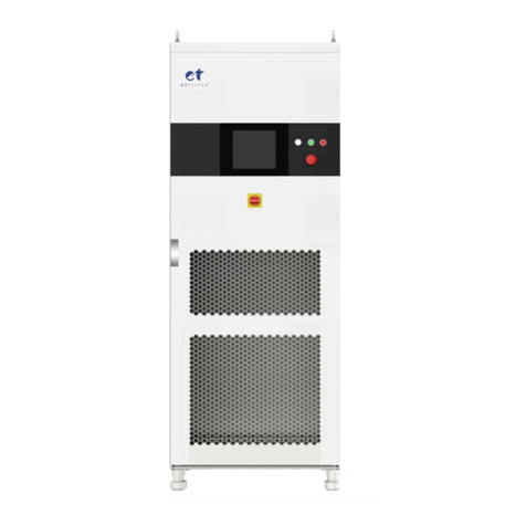
Et system LAB-HP User manual

ETSystemelectronicGmbHTelefon062053948‐0
Fax0620537560
Hauptstraße119‐121info@et‐system.de
68804Altlußheimwww.et‐system.de
LAB‐HP

Softwareversion:V178
May2021

TableofContents
Info&ContactAddresses........................................................................................................................................1
TechnicalSpecifications...........................................................................................................................................1
AmbientConditions........................................................................................................................................................1
InputSpecifications........................................................................................................................................................2
OutputSpecifications.....................................................................................................................................................2
AIInterface.....................................................................................................................................................................3
RS232.............................................................................................................................................................................3
RS485.............................................................................................................................................................................3
TechnicalDrawing..........................................................................................................................................................4
ImportantSafetyInstructions..................................................................................................................................5
InitialOperation.............................................................................................................................................................5
Unpacking.......................................................................................................................................................................5
SettingUp.......................................................................................................................................................................5
VisualInspection............................................................................................................................................................5
MainsOperation............................................................................................................................................................5
FunctionalDescription.............................................................................................................................................6
GeneralSettings......................................................................................................................................................8
Configuration..................................................................................................................................................................8
Contrast..........................................................................................................................................................................8
VoltageSettings......................................................................................................................................................8
UlimitandIlimit...................................................................................................................................................................8
OVP(OverVoltageProtection).......................................................................................................................................8
AI‐Type...........................................................................................................................................................................8
RememberLastSetting..................................................................................................................................................9
M/SMode......................................................................................................................................................................9
Interfaceparameter(Option).........................................................................................................................................9
FrontPanelOperation.............................................................................................................................................9
ConsoleandRotaryPulseEncoder.................................................................................................................................9
DisplayandSettings.......................................................................................................................................................9
Currentmeasurementvalues(Display).....................................................................................................................9
Maindisplay............................................................................................................................................................10
UIdisplay.................................................................................................................................................................10
Operatingmodes..........................................................................................................................................................10
OperatingModeselection.......................................................................................................................................10
Preselectablefixedsettings.....................................................................................................................................11
OperatingModedescription...................................................................................................................................11
Universalinterface(Option)..................................................................................................................................11
Commands...................................................................................................................................................................11
Format.....................................................................................................................................................................11
InstructionSet.........................................................................................................................................................12
Quickviewofcommands........................................................................................................................................12
Detaileddescriptionofcommands..........................................................................................................................13
ResponseString.......................................................................................................................................................21
Ext.Control:Computer..........................................................................................................................................22
GPIB..............................................................................................................................................................................22
StatusWord.............................................................................................................................................................23
ESR‐Register‐Event‐Status‐Register.......................................................................................................................24
RS232Interface............................................................................................................................................................24
InterfaceReconfiguration........................................................................................................................................25
RS485Interface............................................................................................................................................................25
InterfaceReconfiguration........................................................................................................................................26
Ext.Control:AIInterface(Option)..........................................................................................................................26
PinAssignmentAIInterface.........................................................................................................................................26
AnalogInput.................................................................................................................................................................27

SetPointU(USet).....................................................................................................................................................27
SetPointI(ISet)........................................................................................................................................................27
SetPointOVP(UOVP)...............................................................................................................................................28
AnalogOutput.............................................................................................................................................................28
MonitorSetPointU(Umon).....................................................................................................................................28
MonitorSetPointI(Imon)........................................................................................................................................28
MonitorActualValueP(Pmon).................................................................................................................................28
AnalogOutputOVP(UOVPmon)..................................................................................................................................28
MonitorOutputVoltage(UIstmon)............................................................................................................................29
MonitorOutputCurrent(IIstmon)..............................................................................................................................29
DigitalInput.................................................................................................................................................................29
Activation(Ext.Control)..........................................................................................................................................29
Soft‐Interlock..........................................................................................................................................................29
Blocking(Standby)..................................................................................................................................................29
DigitalOutput..............................................................................................................................................................29
Blocking(Standby)..................................................................................................................................................29
Const.Voltagemode(CV)............................................................................................................................................29
Error.............................................................................................................................................................................30
Ext.Control:Ethernet(LAN)...................................................................................................................................30
ManualAssignmentofanIPunderMicrosoftWindows®...........................................................................................31
Monitoringthedeviceviabrowser.............................................................................................................................31
ControllingthedeviceviaTelnet.................................................................................................................................32
Controllingthedeviceviabrowser..............................................................................................................................32
Ext.Control:USB....................................................................................................................................................33
InterfaceReconfiguration.......................................................................................................................................34
DataLogFunction(Option)....................................................................................................................................34
formatofthesavedData.............................................................................................................................................34
ScriptMode...........................................................................................................................................................35
Executing/LoadingaScript..........................................................................................................................................35
Commands...................................................................................................................................................................35
Syntax.....................................................................................................................................................................35
Quickviewofcommands........................................................................................................................................35
Detaileddescriptionofcommands.........................................................................................................................36
Controller..............................................................................................................................................................40
ControlStructurePVsimModeandUserMode..........................................................................................................41
ControlStructureUIPMode........................................................................................................................................41
ControlStructureUIRMode........................................................................................................................................41
Controllerparameters.................................................................................................................................................42
SenseMode...........................................................................................................................................................42
LoadconnectionwithoutSensorConductor...............................................................................................................42
LoadConnectionwithSensorconductor.....................................................................................................................43
LoadDistributionwithoutSensorConductor..............................................................................................................44
Master/SlaveMode(M/SMode)...........................................................................................................................44
OperationModesinMaster/SlaveMode....................................................................................................................45
M/SModeOff.........................................................................................................................................................45
M/SModeParallel..................................................................................................................................................45
M/SmodeSerial.....................................................................................................................................................46
M/SmodeIndependent.........................................................................................................................................46
Overviewoftheconnectedunits................................................................................................................................46
ControllingtheunitinMaster/SlaveModeviadigitalinterface.................................................................................46
Appendix...............................................................................................................................................................48
EquivalentleakagecurrentmeasurementaccordingtoVDE0701.............................................................................48
Notes.....................................................................................................................................................................49

Info&ContactAddresses
ETSystemelectronicGmbH 1
INFO&CONTACTADDRESSES
ETSystemelectronicGmbHwasfoundedin1986intheheartoftheRhine‐Neckar‐Triangle.Asasubsidiaryofaleading
electricityutilitygroup,thecompanyquicklytookonaleadingroleintheareaoflaboratorypowerelectronicsand
associatedelectricalmeasurement.Theexistingknow‐howinpowertechnologiesinthe90sgaverisetothe“Power
Solutions”productdivisionasastrongextensionofthehistorical“Test&Measurement”range.
Since1997,wehavebeenworkingsuccessfullyasanindependent,privatelyheldcompanywithcustomersinalllines
ofbusinessfromindustry,medicalcare,railwaytechnologyandautomotiveelectronics.
Bymeansofourhighverticalrangeofmanufactureandoureverexpandingdevelopmentdivisionwecanfastand
flexiblyadjusttoourcustomers’requirements.NecessaryapprovalssuchasCSA,UL,VDE,TÜVetc.areflexiblycarried
outbyqualifiedpersonnel.Theapprovalproceduresareperformedwithinthescopeofdevelopmentplanningandthus
donotnegativelyimpactthestartofmanufacturing.Permanentmanufacturingcontrolthroughaccreditedlaboratories
andanISO9001compliantqualitymanagementsystemguaranteeaconstanthigh‐levelseries‐productionquality.
Weofferrepairsandadjustmentforunitsoutsideofourwarrantyperiod.Pleasecontactyourlocaldistributorfor
furtherinformation:
PlaceofBusiness:Altlußheim,Germany
VATIdentificationNumber:DE144285482
RegisterCourt:Mannheim,Germany
RegisterNumber:HRB421186
TECHNICALSPECIFICATIONS
AMBIENTCONDITIONS
CoolingFan
Germany
ETSystemelectronicGmbH
Hauptstraße119‐121
68804Altlußheim
Germany
Phone:+49(0)620539480
Fax:+49(0)620537560
em@il:info@et‐system.de
web:www.et‐system.de

TechnicalSpecifications
2ETSystemelectronicGmbH
Operatingtemperature0‐50°C
Storagetemperature‐20‐70°C
Humidity<80%
Operatingaltitude<2000m
Vibration10‐55Hz/1min/2GXYZ
Shock<20G
Weight5kW19kg,10kW26kg,15kW33kg
INPUTSPECIFICATIONS
Version5kW10kW15kW20kW30kW45kW60kW
Connection5wire(3P+N+E)
Input3P/2083x208Vac(187‐229Vac47‐63Hz)
Input3P/4003x400Vac(360‐440Vac47‐63Hz)
Input3P/4403x440Vac(396‐484Vac47‐63Hz)
Input3P/4803x480Vac(432‐528Vac47‐63Hz)
Max.allowednonsymmetry<3%
InputCurrent(3phase)
3P/400model1,211.5Aeff22.9Aeff34.4Aeff45.8Aeff68.7Aeff103.1Aeff137.5Aeff
InrushTransientCurrent2<25<51<76<102<153<229<305
NominalCurrentInternalFuse320A40A60A80A120A180A240A
BreakingCapacity
Fuse/AutomaticFuse3built‐inCircuitBreaker:KLK20A
RecommendedSupplyBreaker
(valueandcurve)
16A
TypeD/K
32A
TypeD/K
63A
TypeD/K
63A
TypeD/K
<80A
TypeD/K
<120A
TypeD/K
<150A
TypeD/K
LeakageCurrent<35mA<35mA<35mA<35mA<35mA<35mA<35mA
Cosphi>0.7>0.7>0.7>0.7>0.7>0.7>0.7
HarmonicContent4
50Hz=72%
100Hz=2%
150Hz=0,9%
200Hz=0,1%
250Hz=11%
350Hz=0.6%
EfficiencyType194%94%94%94%94%94%94%
DissipatedPower300W600W900W1,200W1,800W2,700W3,600W
OUTPUTSPECIFICATIONS
Staticvoltageregulation±0.05%+2mV
Staticcurrentregulation±0.1%+2mA
Dynamicregulation<1‐3ms(typ.)
Ripple<0.2%RMS(typ.)
Stability±0.05%
Programmingaccuracy(Vout)±0.05%+2mV
1fornominalcurrentandnominalvoltage
2fornominalinputvoltage
3internalmainfuse
4totalharmonicdistortioninputcurrent([%]/Iein)

TechnicalSpecifications
ETSystemelectronicGmbH 3
Programmingaccuracy(Iout)±0.05%+2mA
Displayaccuracy(Vout)<±0.5%
Displayaccuracy(Iout)<±0.5%
Isolation3,000V
Overvoltageprotection0‐120%Vmax
CircuitprotectionOC/OV/OT/OP
LineRegulation<±0.1%+2mV
AIINTERFACE
Digitaloutputs
(CV,Standby,Error)
Outputtype:Opencollectorwithpull‐upresistor10kafter+5V
Isinkmax:50mA
Digitalinputs
(Ext.Control,Standby)
Inputresistance:47kΩ
Maximuminputvoltage:50V
Highlevel:Ue>2V
Lowlevel:Ue<0.8V
Analogoutputs(Xmon)
Outputresistance:100Ω
Minimumpermissibleloadresistance:2kΩ
Imax:5mA
Minimumloadresistancefor0.1%accuracy:100kΩ
Analoginputs(Xset)Inputresistance:1MΩ
Maximumpermissibleinputvoltage:25V
Referencevoltage
ReferencevoltageUref:10V±10mV
Outputresistance:<10Ω
Maximumoutputcurrent:10mA(notshort‐circuit‐proof)
5V‐SupplyvoltageOutputvoltage:5V±300mV
Maximumoutputcurrent:50mA(notshort‐circuit‐proof)
RS232
Signalinputs(RxD,CTS)
Maximuminputvoltage:±25V
Inputresistance:5kΩ(Type)
Switchingthresholds:UH<‐3V,UL>+3V
Signaloutputs(TxD,RTS)
Outputvoltage(atRLast>3kΩ):min±5V,Type±9V,max±10V
Outputresistance:<300Ω
Shortcircuitcurrent:Type±10mA
RS485
Maximuminputvoltage±5V
Inputresistance>12kΩ
Outputcurrent±60mAMax
HighlevelUd>0.2V
LowlevelUd<‐0.2V

TechnicalSpecifications
4ETSystemelectronicGmbH
TECHNICALDRAWING

ImportantSafetyInstructions
ETSystemelectronicGmbH 5
IMPORTANTSAFETYINSTRUCTIONS
Pleasereadthismanualthoroughlybeforeputtingthedevice
intooperation.Payregardtothefollowingsafetyinstructions
andkeepthismanualnearbyforfuturepurpose.
Thisoperatingmanualisbasedonthestateoftechnologyatthetimeofprinting.However,itispossiblethatdespite
regularcontrolandcorrection,thepresentdocumentcontainsprintingerrorsordeficiencies.ETSystemelectronic
GmbHassumesnoliabilityforanytechnical,printingortranslationalerrorswithinthismanual.
INITIALOPERATION
UNPACKING
Pleasemakesurethattheshippingcartonandthepackagingisfreeofdamage.Ifexternaldamageisfound,itis
importanttorecordthetypeofdamage.Pleasekeeptheoriginalpackagingtoensurethedeviceisadequatelyprotected
incaseitneedstobetransportedinthefutureorclaimsforcompensationneedtobeasserted.
SETTINGUP
Toavoidelectricshocksandproductfailure,thedeviceshouldbeinstalledinatemperatureandhumiditycontrolled
indoorenvironment.Theambienttemperaturemustnotexceed50°C.Thedevicemustneverbeexposedtoliquidsor
extremehumidity.
VISUALINSPECTION
Theunitmustbeexaminedimmediatelyfordefectsordamagesintransit.Damagescausedduringtransportmaybe
looseorbrokencontrolknobsandbentorbrokenconnectors.Donotusethedeviceifanyphysicaldamageisapparent.
PleaseinformthecarriersandarepresentativeofETSystemelectronicimmediately.
MAINSOPERATION
Makesuretoverifythemodelnumberandvoltagestatedonthenameplate.Damagesduetowrongpowerfeedare
notcoveredbyguaranteeconditions.
Theunitmustonlybeoperatedwhenconnecteddirectlytothe
mains.Toavoiddamage,donotconnecttheunitto
isolatingtransformers,auto‐transformers,magneticcurrent
limitersorsimilardevices.

FunctionalDescription
6ETSystemelectronicGmbH
FUNCTIONALDESCRIPTION
Thefollowingblockdiagramgivesinformationaboutthevariousadjustmentoptions.
Basically,fourdifferentoperationmodesareavailable:
UImodeUnitisoperatedwithcurrentandvoltagelimitation.
UIPmodeUnitisoperatedwithcurrent,voltageandpowerlimitation.
UIRmode
Unitisoperatedwithcurrent,voltageandpowerlimitation.Additionally,thesetvaluefor
voltageiscalculatedbymeansofthepresentoutputcurrenttosimulateaninternal
resistance..
TablemodeSetvaluesforcurrentandvoltagearesavedinatable.Therefore,UIcharacteristicscanbe
easilyadjusted.
Therearethreedifferentwaystoprogramthetable:
PVsimmodeTheUIcharacteristicofasolargeneratoriscalculatedwiththeUo,Ik,UmppandImpp
parametersandthenwrittentothetable.
MemorycardThetablecanbeprogrammedusingascriptfromamemorycard.
Ascriptisasimpletextfile(ScriptControl).
DigitalinterfaceThetablecanbeprogrammedusingthedigitalinterface(UniversalInterface,WAVE
Commandbzw.DATCommand).

FunctionalDescription
ETSystemelectronicGmbH 7
ATE‐Unit
AnATEunithasnofrontpanel.Itcanbecontrolledviaanaloginterface(page26ff)orviauniversalinterface(page11
ff).
ExampletocontroltheLAB/HPovertheuniversalinterface:
ConnectthedevicetotheRS232port(Page25ff,defaultparameter9600Baud,8Databits,1Stopbit,noparity,no
handshake).
Startaterminalprogram(forexampleTerraTermPro).
Typefollowcommands:
*IDN?(TheLAB/HPwillresponsehisIdstring)
OVP,100(Setovervoltageprotectionto100V,noresponse)
UA,10(Setoutputvoltageto10V,noresponse)
IA,1(Setoutputcurrentto1A,noresponse)
SB,R(Enabletheoutput,noresponse)
MU(Readtheactualoutputvoltage)
ConfigurationoftheAIinterfaceviadigitalinterface:
Syntax:AI[,{5|10}[,{UI|UIP}[,<Filterlevel>]]]
Parameter:
5,10 5V‐or10V‐Mode
IP,UIPUI‐modeorUIP‐Mode
Filterlevel rangeofvalues0..10
Examples:
AI,10
AI,5,UIP
AI,10,UI,8
Thechangesaresavedpermanently.
Controlviaanaloginterface:
ConnecttheAIinterfacelikethewiringdiagramonpage27.Closethe“Externcontrolswitch”.
Theadjustmentofsetpointsandtheselectionofanoperationmodeareperformedviaconsole(FrontPanel
Operation),interface(UniversalInterface)oranalog/digitalIO(Ext.Control:AI‐Interface).
Inorderofpriority,commandswhichhavebeensentbyinterfacecomefirst,byanalog/digital‐IOcomesecondandby
keyboardcomethird.Forexample,iftheinterfacespecifiesthesetpoint,thecorrespondingvalueswillbesent‐
irrespectiveofothersettings‐totheoutput.
Anothereasywaytoautomatefunctionsisofferedbyscriptcontrol(ScriptControl).Alistofcommandsissavedto
thescriptmemoryandenablestheusertochangethechronologicalsequenceofcertainsettings.Thescriptmemory
canbeprogrammedviamemorycardordigitalinterface.
Measurementvaluesofthelatestoutputdataarepermanentlyavailableatallinterfaces.Therefore,thepresentoutput
voltagecanbereadfromthedisplayorviadigitalinterface,whilethecontroloftheunitiscarriedoutviaanalog/digital
IO.

GeneralSettings
8ETSystemelectronicGmbH
GENERALSETTINGS
CONFIGURATION
TheconfigurationmenucanbeaccessedbyholdingthebuttonDisplay(lowerbutton)foratleast1second.Thisopens
amenuwheregeneralsettingsoftheunitcanbechanged.
ThesesettingsareUlimit,Ilimit,OVPandRememberlastsetting.Providedtheunitisequippedwiththeseoptions,AIType
andM/Smodecanalsobeselected.
Pushingtherotarypulseencoderselectsindividualparameters.Turningtherotarypulseencoderselectsthedesired
value.PushingthebuttonDisplayasecondtime,openstheconfigurationmenufordigitalinterfaceparameters.
CONTRAST
Aftertheunithasbeenswitchedon,thedisplayshowstheETSystemlogo.Thecontrastofthedisplaycanbeadjusted
byusingtherotarypulseencoder.Afterwards,thecontrastwillbesavedautomatically.
VOLTAGESETTINGS
ULIMITANDILIMIT
Ulimitlimitsthemaximumoutputvoltage.Theoutputvoltageislimitedtotheselectedvalue,irrespectiveofthevalues
thathavebeensetatthefrontpaneloratoneoftheinterfaces.Theadjustmentrangeis0Vuptothemaximumrated
voltageofthedevice.
Ilimitlimitsthemaximumoutputcurrent.Theoutputcurrentislimitedtotheselectedvalue,irrespectiveofthevalues
thathavebeensetatthefrontpaneloratoneoftheinterfaces.Theadjustmentrangeis0Auptothemaximumrated
currentofthedevice.
Thesesettingscanonlybechangedatthedisplayandtheyapplytoallinterfaces.
OVP(OVERVOLTAGEPROTECTION)
Theoutputisshutimmediatelyiftheoutputvoltageexceedstheselectedvalue.Thedisplayindicatesthisstatuswith
theword‚OVP‘.Toresetthiserror,pushthebuttonStandby.TheOVPvalueappliestothefrontpaneloperation.
TheremayapplydifferentvaluesfortheAI‐interfaceandthedigitalinterface.Thedigitalinterfaceisinitializedwiththe
valuewhichhasbeenadjustedonthefrontpanel.Theadjustmentrangeis0Vuptothemaximumratedvoltageofthe
device+20%.
AI‐TYPE
Thisfeatureadjuststhevoltagelevelsofanaloginputsignalsandanalogoutputsignals.Selectablerangesare0‐5Vand
0‐10V.

FrontPanelOperation
ETSystemelectronicGmbH 9
REMEMBERLASTSETTING
Ifthisoptionisactivated(‚On‘),selectedparameterswillbekeptafterablackout.Ifthisoptionisdeactivated(‚Off’),
standardsetting(0V/0A/UI‐Mode)willbeloadedaftersupplyvoltageisenabled.
M/SMODE
ThefollowingadjustmentscanbemadeifM/S‐Modeisactivated(Master/Slave‐Mode):
Offnomaster/slave
Parallelparallelconnectedoutputs
Serialserialconnectedoutputs
IndependentIndependentoutputs,changeofsetvaluesviabusonly
INTERFACEPARAMETER(OPTION)
Thedisplayshowsallavailabledigitalinterfacesandtheirchangeableparameters.Theseparameterscanbeselectedby
pushingtherotarypulseencoderandchangedbyturningtherotarypulseencoder(functionoftheparameters
UniversalInterface).
FRONTPANELOPERATION
CONSOLEANDROTARYPULSEENCODER
Thefrontpanelconsistsofarotarypulseencoder(withbuttonfunction)andtwobuttons.Theupperbuttonswitches
theunitintostandbyorrunmode.
Thelowerbuttonchangesthedisplaymode.Pushingandholdingthisbuttonfor1secondopenstheinterface
configurationmenuforinterfacesettings(DisplayandSettings)andinterfaceparameters(InterfaceParameter).
Therotarypulseencoderadjuststhesetvalue.Pushingtherotarypulseencoderselectsthevaluetobechanged.
DISPLAYANDSETTINGS
Currentmeasurementvalues(Display)
Innormalmode,pushingthebuttonDisplayswitchesbetweentwodifferentoverviewscreens.

FrontPanelOperation
10ETSystemelectronicGmbH
Maindisplay
Themaindisplayshowscurrentmeasureandsetvalues.Ontheleftsideofthisscreen,presentvoltageandcurrent
valuesaredisplayedaswellastheresultingpower(P=U*I)andresistance(R=U÷I).Thesetvaluesaredisplayedon
therightsideofthescreen(‚Preset‘)andvaryaccordingtotheoperationmodeoftheunit.
ThelowerrightsectionofthescreenshowsthecurrentControlModeoftheunit:
LocFrontpaneloperation
ScrMemorycardoperation
AIAnaloginterfaceoperation
RemInterfaceoperation
LLOInterfaceoperation,Frontpaneloperationlocked
DisUnitlockedviainterlockinput(Option)
ThesectiontotheleftofthecontrolmodedisplayshowsthecurrentOperatingStatusoftheunit:
StandbyStandbymode
U‐LimitVoltagelimitationmode
I‐LimitCurrentlimitationmode
P‐LimitPowerlimitationmode
OVPdeactivationoftheunitbyovervoltageprotectionmode
ThesectionabovetheoperatingstatusdisplayshowsthecurrentOperatingModeoftheunit:
UIVoltageandcurrentlimitation
UIPVoltage,currentandpowerlimitation
UIRVoltageandcurrentlimitation,simulatedinternalresistance‐
PVsimsimulationofaphotovoltaiccharacteristic
Usersimulationofauser‐definedcharacteristic
UIdisplay
TheoutputdiagramisdisplayedasanUIcharacteristic.Thepicture
ontherightsideshowstheoperatingmodeUIR.Asmalldotshows
theactualoperatingpointoftheunit.Thediagramisalwaysrelative
totheselectedvalues.Forexample,thecurrentlimitationwouldbe
changedfrom100Ato50A,theinternalresistancewouldbe
doubled,whilethediagramwouldstaythesame.Ahorizontalpartof
thediagramcorrespondsthento50Aandnotto100A.
OPERATINGMODES
OperatingModeselection
Operatingmodescanonlybeselectedwhenthemaindisplayisvisible.Pushingtherotarypulseencoderswitchesthe
focus(selectedmodeisinverted)throughthedifferentmodes.Oncetheoptionisfocused,theoperatingmodecanbe
selectedbyturningtherotarypulseencoder.Theunitneedstobeinstandbymode,otherwisetheoption‚Mode‘isnot
selectable.
UOutputvoltage
IOutputcurrent
POutputpower(UIPmodeonlyUIPmode)
RiInternalresistance(UIRmodeonlyUIRmode)
UmppMPPvoltage(PVsimmodeonlyP
V
simmode)
ImppMPPcurrent(PVsimmodeonlyP
V
simmode)

Universalinterface(Option)
ETSystemelectronicGmbH 11
Preselectablefixedsettings
Fixedsettingscanbesavedandselectedwhichmeansthatfrontpaneloperationisinactive.Foractivationor
deactivationthebuttonStandbymustbepressedandheldwhenthedeviceisswitchedonuntiltheET‐Systemlogo
fadesout.
Toactivatethefixedsettings,thedevicemustbeswitchedonandtheoption‚RememberLastSetting‘mustbeactivated.
Thedesiredsetvaluescanbeadjustedandthedevicemustbeswitchedoff.ThebuttonStandbymustbepressedand
heldwhilethedeviceisswitchedonuntiltheET‐Systemlogofadesout.Thedevicewillloadthelastsetvaluesdirectly
onpowerup.Frontpaneloperationisinactive.Thisstatusissignalizedbytheword‚Dis‘inthelowerrightcornerofthe
display.Todeactivatethismode,thebuttonStandbymustbepressedwhenswitchingonthedevice.
OperatingModedescription
UIMode
InUImode,thesetvaluesforvoltageandcurrentaretransferreddirectlytotheswitchmoderegulator.Thereisno
additionaldigitalcontrol.
UIPMode
InUIPmode,thesetvaluesforvoltageandcurrentaretransferreddirectlytotheswitchmoderegulator.Iftheoutput
currentexceedsthepreviouslyadjustedlimitvalue,thecurrentsetpointwillberegulated.
UIRMode
InUIRmode,thevoltagesetpointisregulatedinawaythatapowersupplyunitwith(adjustable)internalresistanceis
simulated.Thesetvalueforcurrentlimitingistransferreddirectlytotheswitchmoderegulator.
PVsimMode
InPVsimmode,thediagramofaPVgeneratorissimulated.Givenvaluesareopen‐circuitvoltageUo,short‐circuitcurrent
Ik,aswellastheamountsofvoltageandcurrentbywhichthePVgeneratordeliversthemaximumpower(Umpp,Impp).
ParameterscanbefoundinthespecificationsheetofthesimulatedPVgenerator.
ValuesforUmppmaybeinarangefrom0.6to0.95*U.
ValuesforImppmaybeinarangefrom0.6to0.95*I.
ScriptMode
Inscriptmode,theunitiscontrolledbymemorycard.Thedisplay‚Mode‘showsthepresentoperatingmode‚UI‘.The
lowerrightcornerofthedisplayshowstheword‚Scr‘,whichindicatesthatscriptoperationwasselected.Ifthereisno
memorycardintheslot,thisoptioncannotbeselected.Fordetailedinformationaboutmemorycardcontrolandabout
howtobuildupascript,seeScriptControl.
UNIVERSALINTERFACE(OPTION)
Allinterfacesofthedigitalinterfaceareequal.Thereisnoshiftbetweentheinterfaces.Forexample,thefirstcommand
canbeissuedviatheIEEEinterfacewhilethesecondcommandcanbeissuedviatheRS232interface.Thereturnvalues
willbesentfromthatinterfacethecommandwasissuedfrom.
COMMANDS
CommunicationisbasedonanASCIIprotocol.Thefollowingchaptersdescribehowtowriteacommandandgivean
overviewoverthecommands.
Format
Acommandconsistsofthecommandword,aparameter(ifnecessary)andaterminator.Thecharacterforthe
terminatorisCarriageReturn<CR>orLineFeed<LF>.

Universalinterface(Option)
12ETSystemelectronicGmbH
CharacterASCIIDecvalueHexvalue
CarriageReturn<CR>130d
LineFee<LF>100a
Ifthecommandcontainsa<DEL>or<ESC>character,itwillnotbeprocessed.Therefore,acommandcanbecancelled
whileentering.Though,aterminator(<CR>or<LF>)isnecessary.
CharacterASCIIDecvalueHexvalue
Escape<ESC>271b
Delete<DEL>1277f
Commandsarenotcasesensitiveandmaybemixedup.Therefore,theeffectofthefollowingcommandsisthesame:
GTL,Gtl,gTL.Decimalplacesareoptionalandseparatedbyafullstop‘.‘.Thenumberofdecimalplacesisnotlimited.
Therefore,theeffectofthefollowingcommandsisthesame:UA,10,UA,10.0,UA,10.000000000,UA,0010,UA,010.0000
Thenumberofdecimalplacestobeanalyzeddependsonparameterandunittype.Itcorrespondstothenumberof
decimalplaces,acommandwithoutaparameterwouldreturn.Asarule,decimalplacesareanalyzeduntilaresolution
of0.1%isreached.
Example: Evaluation of decimal places
LAB/HP with 600 V, 25 A
600 V * 0.1 % = 0.6 V one decimal place
25 A * 0.1 % = 0.025 A three decimal places
Optional,afteranumericalvalue,alettermaybeaddedtoindicatetheunit.However,thisletterwillnotbeanalyzed.
Example: Attached letter as unit
UA,10.0 V Resets output voltage to 10 V
UA,10.0 m Caution! The ‚m‘ will not be evaluated, output voltage here is also 10 V
Example: A valid command with corresponding hex values
U A , 1 0 . 2 <CR>
55 h 41 h 2 ch 31 h 30 h 2 eh 32 h 0 dh
Example: Adjustment of output voltage 10 V/5 A (full command sequence)
OVP,100 adjusts OVP to 100 V
UA,10 adjusts output voltage to 10 V
IA,5 current limiting 5 A
SB,R output enabled
InstructionSet
TheIEEE‐488.2standarddemandsseveralbasiccommands.Somecommandsmayoccurtwiceforcompatibilityreasons
(onceintheETSversionandonceinthe(old)IEEE‐488.2version).Thefollowingsyntaxisusedtodescribethe
commands:
[]Squarebracketsoptionalparameter
<>Anglebracketnumericalvalue
{}Curlybracketselectionlist
|Verticallineseparatorwithinselectionlist
Example
GTR[,{0|1|2}] means that the command GTR can be used with or without parameters. If a parameter exists, it has to be 1, 2 or 3. Valid
commands are: GTR GTR,1 GTR,2 GTR,3
IA[,<imax>] means that the command IA can be used either with or without parameters. If a parameter exists, it has to be a numerical
value.
Quickviewofcommands
CommandDescriptionResult

Universalinterface(Option)
ETSystemelectronicGmbH 13
CLS*orCLSClearStatusDeletesthestatusbyte
DAT,<U>,<I>DIPDataforuser‐definedcharacteristic
DCLDeviceClearInitializationdatareset
GTLGoToLocalActivatesfrontpaneloperation
GTR[,{0|1|2}]GoToRemoteActivatesdigitalinterfaceoperation
IA[,<imax>]SetImaxAdjustscurrentlimiting
IDor*IDN?IdentificationDisplaysidentificationstring
IMPP[,<impp>]SetImppAdjustsMPPcurrentduringPVsimmode.
LLOLocalLockoutDeactivatesLOCALbutton
LIMILimitIaReadsmaximumadjustablecurrentlimitation
LIMPLimitPaReadsmaximumunitoutput.
LIMRLimitRReadsadjustablerangeforRiwithinUIRmode.
LIMRMAXLimitRmaxReadsmaximumadjustablerangeforRiwithinUIRmode.
LIMRMINLimitRminReadsminimumadjustablerangeforRiwithinUIRmode.
LIMULimitUaReadsmaximumadjustablevoltagelimitation
MODE[,{UI|UIP|UIR|PVSIM|
USER|Skript}]SetModeSelectsoperationmode
MU[,<Nr>]MeasureUaMeasurespresentoutputvoltage
MI[,<Nr>]MeasureIaMeasurespresentoutputcurrent
*OPT?OptionalIdentificationQueryDisplaysunitscurrenthardware/softwareversion
OVP[,<Uovp>]OvervoltageProtectionAdjustsovervoltageprotection
PA[,<Plimit>]SetPmaxAdjustspowerlimitation
PCx[,<baud>,<parity>,
<databits>,<stopbits>,
<handshake>,<echo>,
<timeout>]
Program
CommunicationAdjuststheinterfaces
RA[,<Ri>]SetRiAdjustsinternalresistance
REGLER[,<Nr>,<Kp>,<Ki>,
<Kd>]ControllerParametersAdjustscontrollerparametersforUIP,UIRandPVsimmode
RIor*RSTResetInstrumentResetshardware(noreturnvalue)
SB[,{S|R|1|0}]StandbyEnables/blockstheoutput
SCR[,<CMD>[,<value>]]LoadScriptProgrammingofscriptmemory
SSor*PDUSaveSetupSavespreviouslymadechannelandinterfaceparameteradjustments(noreturn
value)
STATUSStatusQueryoftheunitsstatus(returnvaluesinbinaryformat)(alsoseefollowing
table)
STBor*STB?InterfaceStatus
UA[,<ua>]SetUaAdjustsoutputvoltage(iftherearenoparameters,presentsetpointis
displayed)
UMPP[,<umpp>]SetUmppAdjustsMPPvoltageinPVsimmode(iftherearenoparameters,presentsetpoint
isdisplayed)
WAVEEndUserwaveDataEndstransferofuser‐definedoutputcharacteristic(gradualinterpolationof
intermediatevalues)
WAVELINEndUserwaveDataEndstransferofuser‐definedoutputcharacteristic(linearinterpolationof
intermediatevalues)
WAVERESET,<Um>,<Im>StartUserwaveDataStartstransferofuser‐definedoutputcharacteristic
Detaileddescriptionofcommands
CLS*orCLS‐ClearStatus
Thiscommanddeletesthestatusbyte.Itaffectsonlythestatusbyteoftheinterface,thecommandwassentfrom.No
returnvalue.Fordetaileddescriptionofthestatusbyteseethedifferentinterfacechapters.
DAT,<U>,<I>‐Data
Dataforauser‐definedcharacteristic.Noreturnvalue.FordetaileddescriptionofthiscommandseeWavereset.
DCL‐DeviceClear
Thiscommandresetstheinitializationdata.Noreturnvalue.
Caution:Interfaceparametersarealsoreset!
GTL‐GoToLocal
Thiscommandactivatesfrontpaneloperation.If‚LocalLockout‘(LLO)wasactivatedbefore,itwillalsobereset.No
returnvalue.

Universalinterface(Option)
14ETSystemelectronicGmbH
GTR[,{0|1|2}]‐GoToRemote
Thiscommandactivatesdigitalinterfaceoperation.Theoptionalparameteraffectsthefuturebehavioroftheunitafter
switchon.Settingissavedpermanently.Noreturnvalue.
Optional parameter 0 = Deactivates automatic remote operation
The command GTR must be entered to activate the unit’s remote operation mode. This mode is useful if the unit shall be operated
manually and at the same time, measurement values shall be read out via the digital interface.
Optional parameter 1 = Activates remote operation on first addressing
Unit switches to remote operation when receiving a command via digital interface. The only exception is the GTL command, which switches
the unit to local mode.
Optional parameter 2 = Activates remote operation immediately after switch on
After the unit was switched on, remote mode is immediately activated. Front panel operation is deactivated.
IA[,<imax>]‐SetImax
Thiscommandadjustscurrentlimiting.Enteringthecommandwithoutparametersdisplaysthesetvalue.Iftheset
valueishigherthanthemaximumcurrentoftheunit,therange‐error‐bitwithintheESRregisteroftheinterfaceisset.
Thepresentsetvalueremainsunchanged.IfthesetvalueishigherthantheIlimitvalue,whichwasadjustedbytheuser’s
settings,butlowerthanthemaximumcurrentoftheunit,thecurrentislimitedtotheIlimitvalue.Noerrormessage.
Example: 300 A unit, Ilimit adjusted to 200 A via configuration menu
GTR Remote operation
OVP,200 Over voltage protection 200 V
UA,10 Output voltage 10 V
IA,100 Output current 100 A
SB,R Output open
IA,400 Output current 400 A, this command is ignored, because the current is higher than the maximum current of the device.
„Rangeerror“ is set within the status byte.
IA,250 Output current 250 A, since the output current was limited to 200 A via configuration menu, current limiting is set to 200
A. Error bit is not set.
IA Query of the adjusted current.
IA,200.0A Unit answers: Ilimit = 200 A
In master/slave mode, the current of a programmed device is adjusted. Connected in parallel, the total current is n x IA.
Example:
In M/S mode, 3 devices are connected parallel. IA,10 programs an output current of 10 A. All connected devices are set to 10 A. Since 3
devices have been connected parallel, the total current is 3 x 10A = 30A.
IDorIDN?‐Identification
Thiscommanddisplaystheidentificationstring.Returnvalue:<ID‐String>.
IMPP[,<impp>]‐SetImpp
ThiscommandadjuststheMPPcurrentforPVsimmode.Enteringthecommandwithoutparametersdisplaystheset
value.Ifthesetvalueishigherthanthemaximumcurrentoftheunit,therange‐error‐bitwithintheESRregisterofthe
interfaceisset.Thepresentsetvalueremainsunchanged.IfthesetvalueishigherthantheIlimitvalue,whichwas
adjustedbytheuser’ssettings,butlowerthanthemaximumcurrentoftheunit,thecurrentislimitedtotheIlimitvalue.
Noerrormessagefollows.
Example:
GTR Remote operation
OVP,200 Over voltage protection
UA,50.5 Open circuit voltage of a 50.5 V simulated PV generator
IA,10 Short circuit current of a simulated 10 A PV generato
r
UMPP,40.4 MPP voltage of a simulated 40.4 V PV generato
r
IMPP,8.2 MPP current of a simulated 8.2 A PV generator
MODE,PVSIM Activates PV simulation mode
SB,R Output open
In master/slave mode, the current of a programmed device is adjusted. In parallel connection the total current is n x IA.

Universalinterface(Option)
ETSystemelectronicGmbH 15
LIMI‐LimitIa
Withthiscommandtheusercanreadthemaximumadjustablecurrentlimiting.
Example: 300A unit, Ilimit was adjusted to 200 A via configuration menu
LIMI Query of maximum adjustable current
LIMI,200.0A Unit answers: Ilimit = 200 A
LIMP‐LimitPa
Withthiscommandtheusercanreadtheunit’smaximumoutput.
Example: 10 kW unit
LIMP Query of units output
LIMP,10000 Unit answers: 10 kW
LIMR‐LimitR
WiththiscommandtheusercanreadtheadjustablerangeforRiwithinUIRmode.
Example:
LIMR Query of adjustable internal resistance
LIMR,0.015R,1.00R Unit answers: 15 mOhm up to 1 Ohm
LIMRMAX‐LimitRmax
WiththiscommandtheusercanreadthemaximumadjustablerangeforRiwithinUIRmode.
Example:
LIMRMAX Query of maximum adjustable internal resistance
LIMRMAX,1.000R Unit answers: 1 Ohm
LIMRMIN‐LimitRmin
WiththiscommandtheusercanreadtheminimumadjustablerangeforRiwithinUIRmode.
Example:
LIMRMIN Query of minimum adjustable internal resistance
LIMRMIN,0.015R Unit answers: 15 mOhm
LIMU‐LimitUa
Readsmaximumadjustablevoltagelimitation.Thiscommandrequeststhepreviouslydefinedmaximumoutputvoltage.
Example: 300 V unit was adjusted to 200 V via configuration menu
LIMU Query of maximum adjustable current
LIMU,200.0V Unit answers: Ulimit = 200 V
LLO‐LocalLockout
ThiscommanddeactivatestheLocalbutton.UnitcannotbeswitchedtolocalmodebyholdingthebuttonStandby.
Noreturnvalue.
MI[,<Nr>]‐MeasureIa
Thiscommandmeasuresthepresentoutputcurrent.
Example:
GTR Remote operation
OVP,200 Over voltage protection 200 V
UA,10 Output voltage 10 V
IA,1 Output current 1 A
SB,R Output open

Universalinterface(Option)
16ETSystemelectronicGmbH
MI Measures present output current
MI,0.567A Unit answers: 567 mA
Inmaster/slavemodewithparallelconnectionthetotalcurrentofallconnecteddevicesisdisplayed.Usingthe
parameter<Nr>willshowthevalueofeachconnecteddevice.Numberingstartswith0.
Example:
MI,2 displays the measured output current at the bus of device number 3.
MODE[,{UI|UIP|UIR|PVSIM|USER|Skript|0|1|2|3|4|5}]‐SetMode
Thiscommandselectstheoperationmode.Enteringthecommandwithoutparameterdisplaysthepresentlyselected
operationmode.Enteringthecommandwithparameteractivatestheoperationmode.Alternatively,theoperation
modecanbeindicatedasnumber.
Thefollowingtableshowsthedifferentsettings:
CommandFunction
MODE,UI
MODE,0UImodeisactivated
MODE,UIP
MODE,1UIPmodeisactivated
MODE,UIR
MODE,2UIRmodeisactivated
MODE,PVSIM
MODE,3PVsimmodeisactivated
MODE,USER
MODE,4
User‐definedUIcharacteristicisactivated.Thecharacteristicisdefinedwiththe
commandsDAT,WAVE,WAVELINandWAVERESET.
MODE,SKRIPT
MODE,5
Scriptmodeisactivated.Thescriptisreadfromthememorycardorloadedafter
thecommandSCRhasbeenentered.
MU[,<Nr>]‐MeasureUa
Thiscommandshowsthemeasurementvalueofthepresentoutputvoltage.
Example:
GTR Remote operation mode
OVP,200 Over voltage protection 200 V
UA,10 Output voltage 10 V
IA,1 Output current 1 A
SB,R Output open
MU Measures present output voltage
MU,10.0V Unit answers: 10 V
Inmaster/slavemodewithserialconnectionthetotalcurrentofallconnecteddevicesisdisplayed.Usingtheparameter
<Nr>willshowthevalueofeachconnecteddevice.Numberingstartswith0.
Example:
MU,1 displays the measured output voltage at the bus of device number 2.
*OPT?‐OptionalIdentificationQuery
Thiscommanddoesanoptionalidentificationquery,whichmeansitdisplaysthesoftwareversion.
Example:
Table of contents
Other Et system Portable Generator manuals
Popular Portable Generator manuals by other brands
ESCO Technologies
ESCO Technologies ETS-Lindgren 3107B user manual
REV Ritter
REV Ritter CSM24U instruction manual

CAVIDYNE
CAVIDYNE Caviblaster 1222-E Operation & maintenance manual
Festo
Festo OVEM-...-1P Series Instructions and Operating
Doosan
Doosan G60-SIIIA Operation & maintenance manual
Yamaha
Yamaha EF1000iS owner's manual
Altrad Belle
Altrad Belle MEGAVIB+ Operator's manual

Hioki
Hioki U8793 instruction manual
Endress
Endress ECO Power Line ESE 3000 BS Translation of the original operating manual

Robin
Robin RGV12100 Instructions for use
Powermate
Powermate PL0525312 manual

BRICK
BRICK BG6000RV Translation of the original instructions
