Etaluma Lumascope 500 User guide
IMPORTANT: This Guide describes how to set up the LS500 and LS400 Section I) and get
started on Lumaview 500/400 Section II). It is important that you follow this Guide.
For assistance, please call 760-298-2355 or email support@etaluma.com.
Etaluma, Inc.
Carlsbad, CA 92010 www.etaluma.com
60-298-2355
Lumascope™ and Lumaview™ are trademarks of Etaluma, Inc.
™2009-2015 Etaluma, Inc. All rights reserved.
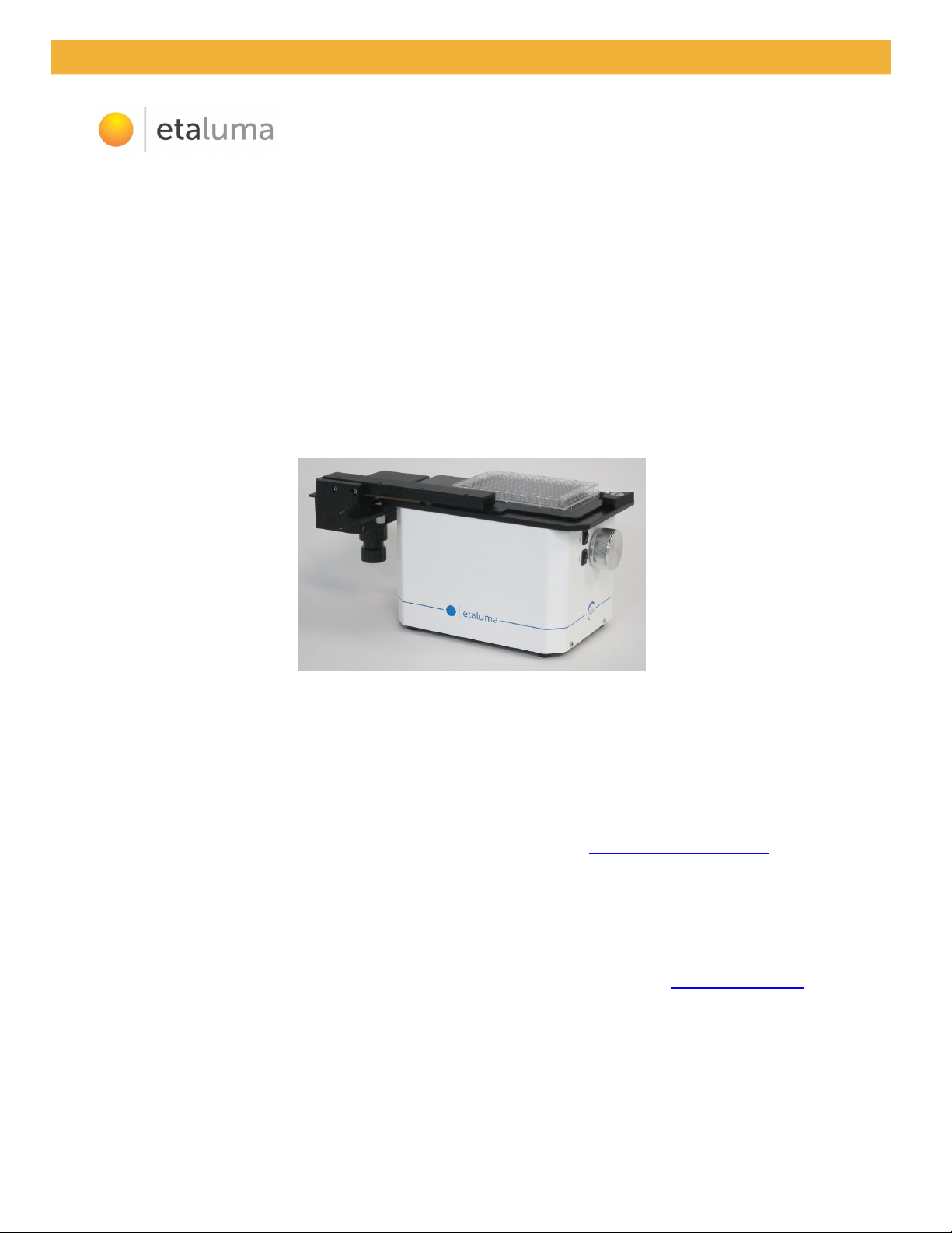
Lumascope 500
with (optional) Manual XY Stage
Lumascope 500/400
-- Startup Guide --
For Use with
LS500
LS400

Lumascope 500/400 Startup Guide
2
Etaluma, Inc. | 3129 Tiger Run Court, Suite 112 | Carlsbad, CA 92010 | 760-298-2355 | www.etaluma.com
This document is available for download at http://etaluma.com/products/downloads.
Note that all steps are described for the LS500 but apply to the LS400 as well unless specifically stated.
I. Hardware: Setup of LS500 and LS400
A. Items included with LS500 (Lumascope 500)
•USB power/communication cable
•Brightfield Illuminator LS500/400
•Fluorescence shroud
•Hex wrench (2 mm)
•External power supply/cord with country-specific plug LS500
B. Items included with LS400 (Lumascope 400)
•USB power/communication cable
•Brightfield Illuminator LS500/400
•Hex wrench (2 mm)
C. Optional Accessories (purchased separately)
•Phase Contrast Accessory LS500/400 (Motic)
•Manual XY Stage for LS620, LS600, LS500, LS400
•Labware Holders
oHolder for 35 mm Petri dishes
oHolder for 60 mm Petri dishes & Terasaki plates
oHolder for microscope slides & 50 mm Petri dishes
•Brightfield Illuminator LS500/400 (to replace the earlier version White LED on flexible cable)
•Objective Removal Tool for Meiji Plan Achromat and Plan Semi Apochromat Objectives
D. First step: Installing Lumaview 500/400 software on your computer
1. LS500 and LS400 are controlled by the Lumaview 500/400 software program. The latest Lumaview
version is downloadable from Etaluma’s website and must be installed prior to connecting your
computer for the first time to the Lumascope (due to the need for a Driver that is installed at the same
time). For a listing of versions and the changes incorporated in each version, see Appendix A at the end
of this document.
2. Lumaview 500/400 will run on Windows XP, , 8, 8.1, and 10, but not Vista. Both desktop computers
and laptops can be used, but the best visualization correlates with resolution of the monitor (note that
the monitor does not affect image resolution unless you are using a low quality monitor that affects
focus). The computer should have Windows .NET Framework 2.0 or higher installed; see
https://msdn.microsoft.com/en-us/library/bb822049%28v=vs.110%29.aspx for more information.
E. Downloading and installing Lumaview 500/400
1. To download Lumaview 500/400, go to http://etaluma.com/products/downloads/. Click on the
Lumaview 500/400 - ZIP link to start the download and save the folder when prompted. Go to your
downloads location and click to open the Lumaview500Install_v(version#).zip file. In the opened folder,
you will see the following two files.

Lumascope 500/400 Startup Guide
3
Etaluma, Inc. | 3129 Tiger Run Court, Suite 112 | Carlsbad, CA 92010 | 760-298-2355 | www.etaluma.com
LS
500_400
Startup
(date)
.pdf
This
Startup Guide
LumaView500
Install_v(version#).msi
Lumaview 500/400
software program
2. Lumaview 500/400 cannot run on a computer with Lumaview 600-Series installed. If your computer
currently has Lumaview 600-Series installed, installation of Lumaview 500/400 may automatically
remove the 600-Series version and leave its drivers intact (which do not affect running of the 500/400
version). If you receive a message saying you cannot install Lumaview 500/400 due to another
Lumaview version being installed, uninstall the Lumaview 600-Series using the quick procedure
described in Appendix B.
3. After downloading Lumaview 500/400, install the program by double clicking on
Lumaview500Install_v(version#).msi. You will be asked about the location; note that the default is a
new or existing Etaluma folder inside the Program Files (x86) folder. During installation, a shortcut icon
named USB Driver Setup will appear on the computer desktop. After installation of the program, click
on the icon to open the USB Driver Installer. Follow the commands to download the Driver. After
installation, a Lumaview icon (orange circle named Lumaview 500-400) convenient for launching the
software will be present on the desktop.
F. Connecting the LS500
1. If connecting with a computer that has been off, turn computer
on. Make sure computer is connected to its monitor. Remove
the LS500 from its packaging. Insert the standard USB-A end of
the supplied USB power/communication cable into a USB port
on your computer and the other square USB-B end into the
square port (middle of the three ports) on the back of the LS500
(see Fig. 1). We highly recommend that you use the same USB
port on your computer every time you connect to the LS500. It
is also best to connect the LS500 directly to the computer USB
port rather than through a USB hub.
If Lumaview 500/400 has not been run previously, it is important that the USB cable be connected first
between the LS500 and computer. This is because Windows needs to load the USB driver before
Lumaview is launched. After the first time, the program can be launched without the USB cable
connected. However, only the Outer Main Window will open (see following section). Connect the USB
cable between the LS500 and computer and the Live Window will open.
2. Launch the Lumaview 500/400 software using the desktop icon and allow the LS500 to be discovered.
This may take a minute or so the first time. Two windows will open on your screen:
a. Live Image Window maximized inside the outer Main Window with upper navigation tabs File,
Windows, and Help. If the Live Image Window is changed to not maximized, it now shows the
name Lumascope and the upper navigation tabs File, Windows, and Help are now present on the
Main Window.
b. Outer Main Window with name Lumaview 500/400 v(version#) - Lumascope. If the Live Image
Window is changed to not maximized, the word Lumascope transfers to become the name of the
Live Image Window and the upper navigation tabs File, Windows, and Help are now present on the
Main Window.
Fig. 1. Photo of Lumascope 500
back panel.

Lumascope 500/400 Startup Guide
4
Etaluma, Inc. | 3129 Tiger Run Court, Suite 112 | Carlsbad, CA 92010 | 760-298-2355 | www.etaluma.com
3. Verify that the Lumaview 500/400 version is the latest version listed in Appendix A. The version
number can be found by clicking on the Help dropdown menu and selecting About.
G. Objectives
1. The LS500 is shipped with the installed objective fully retracted. When used for the first time, it is
necessary to turn the focus knob a number of turns to reach the sample focal plane. Turning the focus
knob clockwise raises the objective and counter-clockwise lowers the objective. The safest procedure
for focusing is to raise the objective until it almost touches the sample and then lower the objective
until focus is achieved.
2. To change objectives, use the supplied 2 mm hex wrench to remove the 4 screws holding the back
panel in place. Move the panel away and with one hand reaching through the deck hole and the other
reaching from the back, carefully switch out the objective. Do not overtighten. Carry out the
replacement quickly to minimize the chance of dust falling onto the mirrored dichroic filter. If any dust
is observed on the filter, carefully blow it off using clean air such as from a compressed air can, making
sure to hold the can upright and bending the straw to aim the air directly toward the filter. If the can is
tilted, liquid can be emitted, which will require further cleaning. Other methods to remove dust may
damage the dichroic filter and must NOT be used.
3. For Meiji Plan Achromat and Plan Semi Apochromat objectives, the optional Objective Removal Tool
can also be used to change objectives. To use the Objective Removal Tool, lower it (grip end up)
through the center hole on the LS500 deck and match the inner notches of the Tool with the notched
pattern on the installed Meiji objective body. Unscrew the objective, and then lower and rotate the
Removal Tool just slightly so the notches no longer line up. This will allow lifting of the objective out of
the LS500 with the Tool. Reverse steps to install the replacement objective.
H. Power
1. For almost all imaging applications, power through the USB cable to the LS500 will be sufficient. If high
levels of illumination are required, e.g., with very dim samples, connect the electrical plug of the
included external power supply/cord into an electrical outlet and the small round plug into the round
port on the back of the LS500 (see Fig. 1).
The external power supply/cord with country-specific plug LS500 is for use with fluorescence and thus
the LS400 does not come with this power supply/cord.
I. Live Cell Imaging with LS500 in an Incubator
1. Prior to imaging in an incubator, place the LS500 inside for 12 hr to allow equilibration to the incubator
temperature.
2. Place the sample on the LS500, focus, and close the incubator door. After 60 minutes, check the focus.
If satisfactory, imaging can be initiated.
3. When live cell imaging at magnifications of 40x and above, the focus can sink several microns as the
mechanism relaxes. If the image has drifted out of focus, estimate the depth of focus change required
to bring the image back into focus and overcompensate the same amount past the point of focus.
Check the focus again after 60 minutes. The image should be in focus and imaging can be initiated.
(Repeat process as needed).

Lumascope 500/400 Startup Guide
5
Etaluma, Inc. | 3129 Tiger Run Court, Suite 112 | Carlsbad, CA 92010 | 760-298-2355 | www.etaluma.com
II. Software: Getting Started with Lumaview 500/400
The following information give instructions for getting started with Lumaview 500/400 and is intended as a
quickstart guide only. Not all options are given and not all features may be explained in any particular
section. The complete User Guide for Lumaview 500/400 is contained in the Help Section after the
program is opened and is accessible by clicking on F1 or the Help dropdown menu/Contents. Becoming
familiar with the complete User Guide is a must in order to use the LS500 properly and take advantage of
the many features of this program.
A. Starting point conditions
1. Lumaview 500/400 has been downloaded to the computer.
2. The LS500 (Lumascope 500) or LS400 (Lumascope 400) is connected to the computer via the UBS
power/communication cable.
3. Lumaview 500/400 is open and the Windows described in Section I.F.2 are visible.
4. Sample to be imaged is present on the LS500 stage (and fluorescence shroud is over sample if imaging
involves fluorescence).
B. Select LS500 or LS400
1. Click on the File dropdown menu in the upper navigation bar and select Set Microscope Version.
2. Click on the appropriate Lumaview version.
C. Note about cursor
1. In older Lumaview versions, the cursor may change to a camera when passed over the Live Image
Window.
2. If you have this version, you should download and install the latest version of Lumaview 500/400 (see
Section I.E above).
3. It you must use the older version, when you left click your mouse or trackpad, either a Save As dialog
box will open or you will hear a clicking sound indicating that the camera has auto-saved an image.
4. Read Section II.G on capturing images below. You can either uncheck the AutoSave function and cancel
the Save As dialog box whenever you left click, or leave the AutoSave function checked and be careful
to left click only when you want to record an image.
D. Illuminating the sample for brightfield
CAUTION: When any LEDs are turned on, do NOT look directly at the light. Be sure to turn off all LEDs at
the end of a viewing session so that any sample remaining on the stage is not photo-bleached.
1. LS500: For best contrast, it is recommended to set the colors to grayscale. Right click over Live Image
Window, select Colors, and choose Green Only, Show as Gray.
LS400: Right click over Live Image Window, select Colors, and choose RGB. Right click again, select
Colors and choose R/G/B Gain Adjustment. The Red/Green/Blue Gain dialog box will open and the
default settings will be present. Place a white sheet of paper over the deck hole (with or without
objective) and adjust the color gain settings so that the Live Image Window shows a gray color.
Typically reducing the Green gain to 64 will be an acceptable adjustment.
2. For viewing in a typically lit area, ambient light is generally adequate to see brightfield. The light should
be as uniform as possible to prevent shadows or other dark or light areas. Overhead fluorescent

Lumascope 500/400 Startup Guide
6
Etaluma, Inc. | 3129 Tiger Run Court, Suite 112 | Carlsbad, CA 92010 | 760-298-2355 | www.etaluma.com
lighting can cause uneven brightness including a striped pattern; if observed, move the LS500 or
partially shade the light to reduce unevenness across the sample.
For the best brightfield, use of the a) previously included white LED on flexible cable, b) included (or
purchased separately) Brightfield Illuminator LS500/400, or c) light source of the (optional) Phase
Contrast Accessory LS500/400 is recommended (see Section I.C. above). Using one of the 3 light
sources also allows control through Lumaview. Note: Although the LS500 camera is full color, a green
filter is installed for green fluorescence and thus brightfield images will be in black and white
(grayscale) or the same grayscale pseudo colored with green. The LS400 does not have the green filter
installed and thus the images will be full color brightfield.
3. To connect the white LED on flexible cable, plug the USB end into the USB port on the back on the
LS500 (see Fig. 1). To connect the Brightfield Illuminator LS500/400, first remove the LS500 back panel
using the supplied 2 mm hex wrench and replace it with the new back panel attached to the Brightfield
Illuminator. Adjust the Brightfield Illuminator height by loosening the 2 screws on the back bracket
using the 2 mm hex wrench. If using the light source of the Phase Contrast Accessory LS500/400,
remove the slider (or use a slider position with no mask) and adjust the illumination brightness by
moving the horizontal lever on the Condenser front and/or the circular knob on the phase power cable.
4. For viewing in a dark environment such as an incubator, a light source such as one of the 3 listed in
Section D.2 above is needed. Connecting one of these 3 light sources to the LS500 allows it to be
controlled by Lumaview 500/400. To mount the light source above the Lumascope deck, see Section
D.3 above.
5. To illuminate the sample when using ambient light, move cursor over Live Image Window, right click,
and select Exposure Settings to open its dialog box. Check Auto Gain to most easily acquire the best
grayscale (ignore Gain % and Exposure % settings).
If using the white LED on flexible cable or the Brightfield Illuminator LS500/400, right click over Live
Image Window and select Illumination Settings to open its dialog box. Flip switch labeled B on focus
knob side of LS500 to the ON position. (The LS400 does not have the 2 switches on the side.) Right click
over Live Image Window again and select Exposure Settings to open its dialog box. In Illumination box,
check White LED. In Exposure box, check Auto Gain to most easily acquire the best grayscale (ignore
Gain % and Exposure % settings).
If using the light source of the Phase Contrast Accessory LS500/400, flip the switch on top of the
condenser to REMOTE to control the light through Lumaview 500/400. Follow the same steps as listed
in the previous paragraph for the white LED on flexible cable or Brightfield Illuminator LS500/400 to
illuminate the sample.
When using the light source of the Phase Contrast Accessory LS500/400, if the switch on top of the
condenser is in the ON position, the Phase Contrast Accessory will not take instructions from Lumaview
500/400 and there is no need for the phase signal cable (see the Phase Contrast Accessory User Guide
at http://etaluma.com/products/downloads/ for more information). To turn on the light, ensure that
the phase power cable switch is in the ON position. The light can then be controlled by adjusting the
horizontal lever on the condenser front or turning the knob on the phase power cable.

Lumascope 500/400 Startup Guide
Etaluma, Inc. | 3129 Tiger Run Court, Suite 112 | Carlsbad, CA 92010 | 760-298-2355 | www.etaluma.com
E. Illuminating the sample for fluorescence (not applicable to the LS400)
CAUTION: When any LEDs are turned on, do NOT look directly at the light. Be sure to turn off all LEDs at
the end of a viewing session so any sample remaining on the deck is not photo-bleached.
1. Choosing between green pseudo coloring and gray scale is a matter of choice. For green pseudo
coloring, right click over Live Image Window, select Colors and choose Green Only. For grayscale, right
click over Live Image Window, select Colors, and choose Green Only, Show as Gray.
2. With cursor over Live Image Window, right click and select Illumination Settings to open its dialog box.
Right click again and select Exposure Settings to open its dialog box. Settings in these two dialog boxes
are typically adjusted together. Flip switch labeled F on focus knob side of Lumascope to the ON
position.
3. In Illumination box, check FL LED for green fluorescence. Start with Gain as low as possible and
Exposure at maximum. Adjust Illumination to desired brightness. For dim samples, if Illumination is at
maximum level (> 50%), increasing the Gain can be used to increase the signal (but Gain will also
increase background as well).
F. Focusing
1. Unless approximate sample focus level is known, it is best to initially raise the objective to maximum
height (without hitting sample) and then turn the focus knob counter-clockwise until sample comes
into focus.
2. Ensure you are focusing on correct sample plane and not another surface, for example, back side of a
microscope slide. If uncertain, place a similar but easy to focus sample on stage, focus, and then switch
to new sample. Clicking on magnifier glass icon on top bar of Live Image Window zooms in on image so
it fits the monitor screen horizontally and should help you to focus. If necessary, increase or decrease
LED brightness and/or Gain.
G. Capturing images
1. With cursor over Live Image Window, right click and select Image Parameters to open its dialog box.
Click on File Type dropdown menu and select format type desired. The TIFF format is recommended
due to several features as explained in Help/Image Types. Select or enter the Filename Root and Saving
Destination (e.g., a new folder set up on the desktop). Choose Image Rotation if desired.
Checking Auto Save Demand Capture will automatically save the images to your Destination Folder with
your Filename Root and a number based on time (incorporates day of the year down to milliseconds).
If not checked, a Save As dialog box will open every time an image is taken that allows naming and
choosing the destination for that image. Click Save to save your image settings.
2. When desired field has been illuminated and focused in Live Image Window, hover the cursor over the
camera icon on top tool bar until it is outlined in blue. Left click the camera icon to capture the image.
3. For quick review of your last image, click the folder icon on the top tool bar to launch Windows
Explorer, which will open the most recent Destination Folder.

Lumascope 500/400 Startup Guide
8
Etaluma, Inc. | 3129 Tiger Run Court, Suite 112 | Carlsbad, CA 92010 | 760-298-2355 | www.etaluma.com
H. Capturing time-lapse series
1. It is first necessary to download and install the following two freeware programs.
a. AviSynth video post-production program found on the AviSynth Wiki at
http://avisynth.nl/index.php/Main_Page. Download and install the Official Build. The default save
location for the program will be the Etaluma folder inside the Program Files (x86) folder.
b. MeGUI video conversion program found at http://sourceforge.net/projects/megui/. After the
zipped folder (MeGUI_2525_x86.zip) has downloaded, click to open and Extract All. Depending on
your computer and Windows version, it may be necessary to right click on the .zip file to complete
the extraction. After extracting the files from the zipped folder, you will see the file MeGUI
Application with a green icon in the MeGui_2525_x86 folder. Extraction so that the green icon is
shown is essential for the images to be scripted correctly for video compiling. If desired, make a
shortcut on your desktop.
2. Before initiating a time-lapse study, review Computer Configuration in the Help Section and change
your power and Windows update settings so they do not automatically turn on and interfere with
scheduled image captures. Of particular importance are Sleep Mode and Auto Restart. After time-
lapse is completed, be sure to change the settings back.
3. With cursor over Live Image Window, right click and select Time Lapse Settings to open its dialog box.
4. For brightfield images, check White in the Activate column (be sure FL is not checked). Check Auto Gain
(ignore Gain % and Exposure %). Do not click on Load Present Values.
5. For fluorescent images (not applicable to the LS400), check FL in the Activate column. To set LED %,
Gain % and Exposure values, use desired levels determined in Section II.E above or determine now and
click Load Present Values. Time Lapse can also include brightfield in a darkened space (will require one
of the 3 light sources described in Section II.D.2), in which case the White box would also be checked as
well as its Auto Gain.
6. Choose Saving Destination Folder, Filename Root, and Filename Starting ID number. The Destination
Folder should be unique for each time-lapse because of how the images are compiled into scripts. File
format is selected in the Images dialog box accessed by right clicking over the Live Image Window and
selecting Image Parameters.
. Set Duration and Interval values and LED Pre-Snap Time (a typical time is 1 second). Images will be
numbered sequentially and collected in the Destination Folder along with an Avisynth (.avs) file
containing a compiled script of the captured images.
8. Be sure to click Save.
9. Start series by clicking on clock icon in top tool bar of Live Image Window. Depending on the Lumaview
version, you may see another dialog box open asking if you wish to start time-lapse. Click yes. To stop
image capture at any time, click on clock icon again. You may be asked if you wish to stop time-lapse
and if so, click yes.
I. Compiling time-lapse images into videos
1. Click on the MeGUI Application to open the program (may take several minutes).

Lumascope 500/400 Startup Guide
9
Etaluma, Inc. | 3129 Tiger Run Court, Suite 112 | Carlsbad, CA 92010 | 760-298-2355 | www.etaluma.com
2. At the end of the AviSynth Script line near the top, click browse (“…”). A MeGUI window named Open
AviSynth script will open. Depending on the Windows version used, the Destination Folder from the
most recent time-lapse capture may be listed. Or it may be necessary to browse to your Destination
Folder. If your time-lapse included both fluorescent and brightfield images, your Destination Folder will
contain 2 subfolders, each with the images and corresponding .avs file for that channel. Open the
desired folder or subfolder and click on the Avisynth (.avs) file.
3. A preview video window will open; click Play to see a short segment of your video.
4. Return to the MeGUI window and select File Format (MP4 recommended). Click Queue button for
Video encoding on right (button about halfway down the window).
5. An encoding window will open and you will see progress in a green horizontal bar until video is
completed and window closes. Close MeGUI window.
6. Video will be saved the Destination Folder or the channel subfolder within the Destination Folder
chosen in Section II.H.6 above.
J. Recording live videos
1. First download and install the AviSynth and MeGUI programs as described in Section II.H.1 above.
2. Click red circle icon in top tool bar of Live Image Window to open Video Configuration dialog box.
3. Choose Filename Root, File Format (TIFF recommended), Destination Folder and if time-stamp is
desired. Click OK and images will start to record.
4. Click red circle icon again to stop. A dialog box will open stating that your images have been saved to
the Destination Folder (and how to proceed as also listed below). The Destination folder will also
contain an Avisynth (.avs) file containing a compiled script of the captured images.
5. To convert the captured images to video, open the MeGUI program (may take several minutes).
6. At the end of the AviSynth Script line, click browse (“…”). A MeGUI window named Open AviSynth
script will open. Browse to your Destination Folder and select the Avisynth (.avs) file.
. Click Open. A preview video window will open; click Play to see a short segment of your video.
8. Return to the MeGUI window and select File Format (MP4 recommended). Click Queue button for
Video encoding on right (button about halfway down the window).
9. An encoding window will open and you will see progress in a green horizontal bar until video is
completed and window closes. Close MeGUI window.
10. Video will be saved in the Destination Folder chosen in Section II.J.3 above.

Lumascope 500/400 Startup Guide
10
Etaluma, Inc. | 3129 Tiger Run Court, Suite 112 | Carlsbad, CA 92010 | 760-298-2355 | www.etaluma.com
For questions or comments, telephone the phone number below, email support@etaluma.com, or submit an inquiry
through the Etaluma website at www.etaluma.com/contact/. An Etaluma representative will be happy to assist you.
Appendix A
Versions of Lumaview 500/400
Version Changes Compared to Previous Version
15.9.23 Improvements in time-lapse image capture and video creation, including use of Duration and Interval
(both in HH:MM:SS format) for setting time points, automatic creation of AviSynth script files, and
images named with numbers in sequence as needed by AviSynth. Added pixel-intensity display in Live
Image Window status bar for determining level of pixel saturation. Added creation of log file for each
channel during time-lapse; files contain file sequence number, date and time in ms resolution.
15.5.11 Red/green/blue color gain adjustment
15.3.31 Added option to select between LS500 and LS400. When LS400 is selected, fluorescent LED controls
are hidden in Illumination and Time Lapse dialog boxes. LumaView changed to Lumaview, eliminated
option for saving images by left clicking of mouse, eliminated playing of WAV file when image is
saved.
14.10.28 (a) Fixed a bug where the incorrect data rate was displayed in the live image window; (b) Added the
exposure time (in milliseconds) to the 'Exposure' dialog; (c) Fixed a bug in that the false video rate
was saved to the AviSynth script file.
14.9.3 Scale-bar bug fix. The scale was incorrect.
14. .9 Video capture at full-frame rate using freeware – the recommended freeware is used after the
images are captured, the same freeware could be used to convert time-lapse images to video too;
optional scale-bar on image; optional date/time stamp on image; improved help; finer LED brightness
granularity; robust behavior for plugging in and out of the USB cable; simplified dialog boxes.
Appendix B
Installing Lumaview 500/400 on a Computer with a Different Lumaview Version Installed
1. If Lumaview 600-Series (which may be Lumaview 600 or Lumaview 620) is already installed on your
computer, it may be necessary to uninstall the software program before installing Lumaview 500/400.
Go to C:/Program (x86)/Etaluma folder and inside will be a folder named Lumaview 620 or
Lumaview600. Go to Control Panel/Programs & Features, right click on the Lumaview 620 or 600 file,
and click Uninstall. After uninstall is completed, verify that the Lumaview 620 or 600 folder is now gone
from the C:/Program (x86)/Etaluma folder. You are now ready to install Lumaview 500/400 (Section I.E
above).
2. If you have an older version of Lumaview 500/400 already installed and want to replace it with the
newest version, download the new version from the Etaluma website (Section I.C. above). You will
most likely not see the Device Driver Installation Wizard open because the new version uses the same
driver.
3. If you previously installed any version of Lumaview 500/400 and then installed Lumaview 600-Series
over it (replaced the 500/400 version), the 500/400 driver should still be present and you most likely
will not see the Device Driver Installation Wizard open. This is because the 500/400 driver (Windows

Lumascope 500/400 Startup Guide
11
Etaluma, Inc. | 3129 Tiger Run Court, Suite 112 | Carlsbad, CA 92010 | 760-298-2355 | www.etaluma.com
Driver Package – Bitwise Systems QuickUSB) has remained on your computer. We recommend leaving
the drivers installed if you may be going back and forth between different Lumascope models.
This manual suits for next models
3
Table of contents
Popular Thermostat manuals by other brands

Robertshaw
Robertshaw 9701i Quick start installation manual

Lux Products
Lux Products SMART TEMP TX9600TS Installation and operating instructions

Dettson
Dettson R02P034 Installation instructions and homeowner's manual

Hunter
Hunter 44127 owner's manual

Bryant
Bryant Legacy Touch-n-Go T2- PHP01- A owner's manual

American Standard
American Standard ONE T064.730 Features & dimensions


