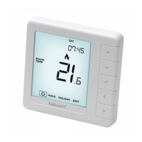
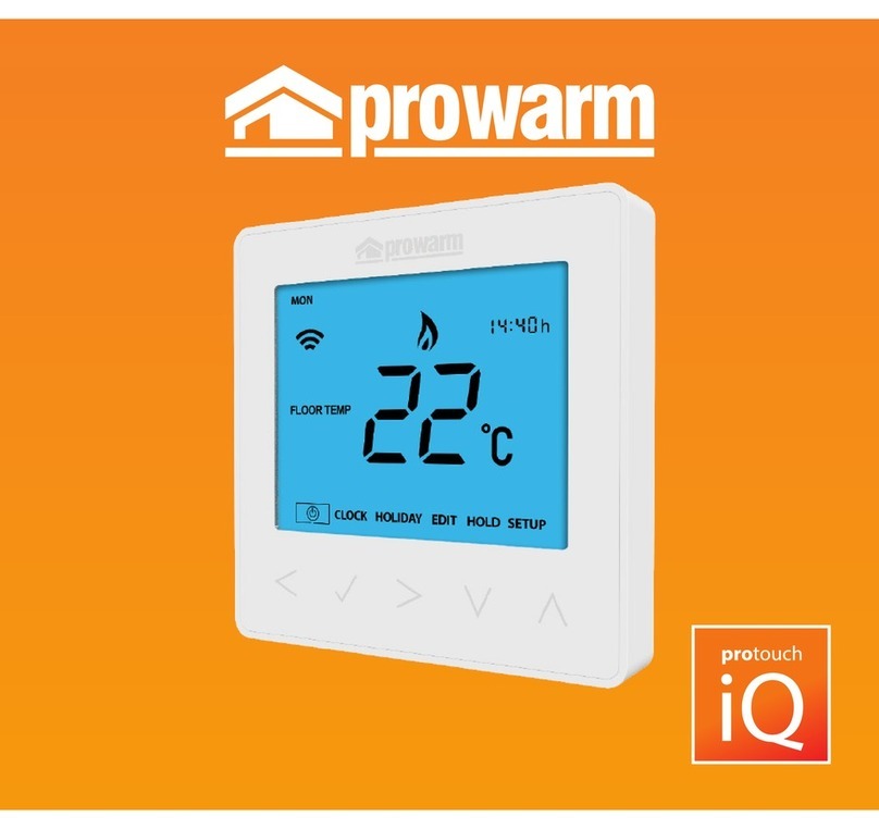
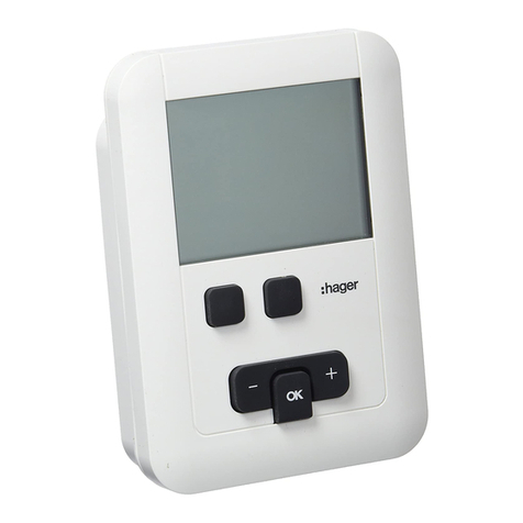
prowarm ProTouch-W Assembly instructions

INSTRUCTIONS
AND USER GUIDE
Smart Thermostat
INSTALLATION AND WIRING INSTRUCTIONS
Loosen fixing screw
located in the bottom of
the thermostat to get the
front panel.
Connect the
thermostat
according to the
Wiring Instruction.
Insert the back
panel into wall box
with provided
screws.
Align top part of front
panel and back panel to
fit these two parts. Then
fix them with screw.
12
43
NOTE: Thermostat should be mounted in a 35mm deep single gang back box

THERE ARE TWO PAIRING METHODS.
IF METHOD ONE DOES NOT WORK PLEASE ATTEMPT PAIRING METHOD TWO
PAIRING YOUR THERMOSTAT TO YOUR APP
‘ProTouch WiFi’ app available from
First download the ProWarm ProTouch App from APP store or Google Play.
You should see the following App icon:
Once downloaded you will need to create an account via email and log in to the App.
You Must ensure that the App has permission to access your location on your phone
settings. The App will ask you this when you install it.
Please also ensure you are connected to your household WIFI during this process.

Step 1
Log in or sign up the
APP through Phone No.
or your Email address.
Step 2
Click “Add Home”,
fill in the information
about the Home.
Step 3
Click Add Device or the ‘+’ symbol
at the top right corner of the screen.
Then click Add Manually followed by
WIFI Thermostat.
St
1
St
ep
3
PAIRING METHOD 1
Note: If you have multiple thermostats that require pairing, please turn all other devices off except the one you
are trying to pair. Once paired this device can be left on whilst pairing another one.
On the thermostat you should see the WIFI symbol flashing fast (2-3 times per second). If the symbol is not
on the screen press and hold the
△
and
▽
arrows for 3 seconds you should see F1 Appear. If F2 appears,
repeat until F1 appears. The WIFI symbol should now begin to flash.

Step 4
Press the button ‘Press
to Connect’ at the
bottom of the screen
and it will ask for your
WIFI password.
Step 5
Enter your WIFI password
from your router ensuring it
is accurate and then press
Confirm. Your App will now
begin the pairing process
with the thermostat.
Step 6
When the connection
is successful, enter a
name for your
thermostat e.g.
Living Room, and
then press Done.
Step 7
Once complete, a
firmware update may
be required. You will
have full access to the
thermostat settings and
functions via the App.

Step 2
Ensure you are connected to your WiFi network and
open the ProTouch WiFi application on your device,
Once open log in to your account following the steps
on screen.
Step 1
On the thermostat press and hold the UP and DOWN arrow together until F2 appears, If the code F1 appears
release the UP and Down arrows and repeat the steps. Please note F2 will disappear from the screen and the
WiFi icon will begin to flash slowly.
PAIRING METHOD 2 Connecting WIFI stats using AP mode
Step 3
In the ProTouch Application press the Plus
symbol at the top of the screen to add a new
device, select WiFi Thermostat.

Step 4
On the add device screen you
need to select AP Mode in the top
right corner, once AP Mode is
selected press the orange button
“Press to Connect” and enter your
WiFi details. Please make sure
these details are correct. Ensure
you have selected the correct WiFi
network and that the password
you enter is accurate, as this will
not work if miss typed. Press the
orange button “Confirm”.
NB: When using an iPhone you will need to
click on ‘Otherwise’ followed by AP mode.
Step 5
Continue following steps that appear on
screen pressing the orange button “Go to
Connect” this will open your Phones WiFi
Settings. Select WiFi hotspot named
SMARTLIFE-XXXXX, once connected to
SMARTLIFE-XXXXX return back to the
ProTouch Application.
Step 6
Once the connection
process is complete press
done, a firmware update
maybe required. Once
complete the thermostat
will be accessible via the
application

THERMOSTAT DESCRIPTION
The new ProTouch WiFi is a smart thermostat used to control your water heating system. It will keep your
home at comfortable temperature whilst minimizing energy use. Install the app on your smart phone to control
your heating system remotely with the WiFi thermostat.
THERMOSTAT DESCRIPTION
TECHNICAL SPECIFICATION
Supply voltage: 50/60Hz 220-240V AC
Max load: 3A
Standby power: <2W IP rating: IP21
Max wire diameter: 侑2.5mm²
MAIN FUNCTIONS
Key-lock
Open window detection
Off time frost protection
Floor temperature limitation
Optimum start
Power consumption
monitor (in APP)
Holiday function
Time display
Hold function
TH
E
TE
C
S
up
Ma
x
St
an

Frost symbol
Key lock indicator
WiFi
Floor Temp
Room Temp
Set
Flame symbol
Temperature
Program Parameter edit
Holiday Parameter edit
Clock Parameter edit
Day indicator
Period indicator
Holiday left
Hold left
Clock
Degrees Celsius
Fahrenheit
Floor limit symbol
Advanced Setup
Hold parameter edit
TEMP
HIGH
SET
ROOM TEMP
FLOOR TEMP
HOLD
h
HOLIDAY
EDIT
SAT
FRITHU
WED
MON TUE SUN
WAKE LEAVE RETURN SLEEP LEFT
HOLIDAY HOLD SETUP
Smart Thermostat
Confirm DownUpReturn Power
DISPLAY SYMBOLS

FUNCTION & USER OPERATION
Press to turn on/off
Note: When frost protection mode is active, the thermostat will maintain the frost protection temperature
when in power ‘off’ mode.
Temporarily override temperature
In normal timed power ‘on’ mode, press
△
or
▽
to
change the current period temperature setting. The new
set temperature will flash for 30 seconds. The
thermostat will revert to the normal programmed setting
at the start of the next time period.
Key-lock
Setting Key-lock can prevent children and others from
switching thermostat parameters. In normal timed
power ‘on’ mode, press for 3 seconds to lock the
thermostat and again for 3 seconds to cancel.
Set the Time
In normal timed power ‘on’ mode, Press
Oand the CLOCK symbol will flash.
Press O again to enter day set.
Press
△
or
▽
to set day.
Press O to confirm and enter hour set.
Press
△
or
▽
to set hour.
Press O to confirm and enter minute set.
Press
△
or
▽
to set minute.
Press O to confirm then press to
revert to normal screen.
Note: The WiFi version updates the time
automatically when connected to internet.

Holiday mode
The thermostat will maintain frost protection
temperature until the holiday days ends.
In normal timed power ‘on’ mode, press O to
enter setting.
Press
△
or
▽
to select HOLIDAY.
Press O to enter holiday days set.
Press
△
or
▽
to set holiday days .
Press O to confirm and return to the normal
screen.
Note: In holiday mode, ‘HOLIDAY LEFT’ and
the days remaining will show on display.
Set the holiday days to 0 to cancel holiday
mode.
Hold mode
The thermostat will maintain a ‘Hold Temperature’ permanently
until the unit is changed back to smart mode or until Hold
Mode is turned off.
1. In normal Power ‘on’ mode, Press O to enter bottom menu.
2. Press
△
or
▽
to move across to HOLD.
3. Press O to enter Hold function settings.
4. Press
△
or
▽
to change Hold Mode to ‘ON’.
5. Press O to confirm and the temperature will now flash.
6. Press
△
or
▽
to change the number to the desired
temperature (we recommend between 24-27deg for a
comfortable floor temperature).
7. Press Oto confirm and the thermostat will revert to the
home screen. HOLD should show on the display.
To turn hold mode OFF, repeat steps 1-4, but in step 4 set
the hold mode to OFF instead of ON followed by the ‘O’ to
confirm.

Timer setting
Each day of the week has 4 time periods,you should allot a temperature to each time period. Set the
temperature above room ambient temperature and the heating will come on until the desired temperature is
reached, or, set the temperature low and the heating will not come on during that time period. The default
settings are shown in the table below.
In normal timed power ‘on’ mode, press O to enter setting.
Press
△
or
▽
to select EDIT.
Press
△
or
▽
to select the day to be set.
Press
△
or
▽
to select the period to be set.
Press
△
or
▽
to select start time hour.
Press
△
or
▽
to select start time minute.
Press
△
or
▽
to select temperature.
Press O to enter day selection.
Press O to enter period selection.
Press O to enter start time set.
Press O to enter minute set.
Press O to enter temperature set.
Press O to confirm and move on to next time period.
Press to revert to normal screen.
Period parameter table (Default)
Mon - Fri 07:00 22삸08:30 19삸
08:30 22삸
17:00 22삸22:00 19삸
22:00 19삸
17:00 22삸
08:00 22삸
Sat - Sun
Day Wake Leave Return Sleep

1
2
3
No. Name Default value Ranges
Room temperature calibration 0°C
0°C
ON
- 5°C -- 5°C
- 5°C -- 5°C
OFF/ON
Floor temperature calibration
Frost protection mode
4
5
6
7
8
9
11
5°C
30°C
00: °C
5°C -- 15°C
00: Built-in sensor
01: Floor sensor00: Built in sensor
02: Both sensors
20°C -- 50°C
00: °C
01: °F
00: 00 s
01: 30 s
02: 60 s
03: 90 s
00: 0.5°C
01: 1.0 °C
02: 2.0 °C
03: 3.0 °C
00: 7
01: 5+1+1
Frost protection temperature
Sensor selection
Floor temperature limit(both sensors)
Temperature unit
Output delay
Switching Differential
Schedule
00: 00s
01: 1.0°C
00: 7
10 01: ON
00: OFF
Reverse output 00: OFF
12 00: OFF
01: ON
Adaptive function 00:OFF
13 00: No
1: YES
Reset 00: No

1. Room temp calibration: Calibrate the temp detected by room sensor.
2. Floor temp calibration: Calibrate the temp detected by floor sensor.
3-4. Frost Protection Mode: Frost protection allows the thermostat to turn on if the temperature drops
below 5 degrees even when it is not programmed to. ❄ displays when you turn off the thermostat.
5. Sensor selection:
00 Room sensor: Run by room sensor.
01 Floor sensor: Run by floor sensor.
02 Both sensors: Run by room sensor with floor temp limit.
6. Floor temp limit: If you choose both sensors, floor temp limit must be set to protect floor.
7. Temp unit: °C and °F can be selected.
8. Output delay: This option help you avoid inadvertent operation on heating.
9. Switching Differential: The number of degrees the temperature has to change before the unit switches
on/off. The default is 1 degree so if the temperature is set to 21 degrees the thermostat will switch on at 20.5
degrees and off at 21.5 degrees. 0.5 degrees either side of 21.
10.Reverse output: This function is designed to operate cooling systems. The unit will click on when the
room is too hot and click off when the room has cooled down.
11. Schedule: Select a weekly schedule for the Edit. There are 2 options:
7: each day from Mon to Sun can be set individually.
5+1+1: 5 days from Mon to Fri have the same events, Sat and Sun can be set individually.
12. Adaptive function: After several days of installation and use, Adaptive function ensures that the required
temp has already been reached when the next event begins.
13. Reset: All parameters are restored to default values.
ADVANCED SETTING

Open window detection
This function only works when room sensor or both sensors is selected. The thermostat with this function will
shut off automatically for 15 min when the window opens, as it can detect that the room temp plummets..
TROUBLESHOOTING
Fault Codes
E1 = Built-in sensor short-circuit or disconnected.
E2 = Floor sensor short-circuit or disconnected.
Note: Should a sensor fault display, please contact us for assistance.
ADVANCED SETTING (Please refer to table above)
Caution: These are normally set by technicians during initial installation.
In normal timed power ‘on’ mode, press O to enter setting.
Press
△
or
▽
to select SETUP.
Press O to enter advanced setting. Each parameter can be accessed by pressing O and adjust the values as
required using the arrow keys. (The default values are recommended and changing these may adversely
affect the way the thermostat works). Press to revert to normal screen.

WIRING INSTRUCTIONS
Ensure power is disconnected when wiring!
MAX LOAD: 3A
SENSOR
N1 L NO
POWER
220-240v
50/60Hz
IP 21
COM
SUPPLY
220-240v
SWITCHING MAINS VOLTAGE
SWITCH
LIVE
OPTIONAL
FLOOR SENSOR*
(NOT INCLUDED)
FLOOR
SENSOR
MAX LOAD: 3A
SENSOR
N1 L NO
POWER
220-240v
50/60Hz
IP 21
COM
SUPPLY
220-240v
SWITCHING LOW VOLTAGE
12/24v
OUT
12/24v
IN OPTIONAL
FLOOR SENSOR*
(NOT INCLUDED)
FLOOR
SENSOR
*NB: No Polarity on floor sensor terminals

www.prowarm.comSupport: 01268 567019
42
2616
87
87
51
51
60
DIMENSIONS (mm)
Smart Thermostat
Table of contents
Other prowarm Thermostat manuals
Popular Thermostat manuals by other brands
Synapse
Synapse CONTROL-485-101 quick start guide

Honeywell
Honeywell T8401C1031 installation instructions
Smart temp
Smart temp SMT-400 User& installer's manual
TOTALINE
TOTALINE P/N P474-2150 owner's manual
Mod-tronic
Mod-tronic Series 40T Specifications-installation and operating instructions
Full Gauge Controls
Full Gauge Controls Microsol FLT Advanced quick start guide
