ET&F 610 Operator's manual

INSTRUCTION MANUAL AND SAFETY INSTRUCTIONS
DANGER
Improper and unsafe use of this Nailer will result in death or serious injury!
This Manual contains important information about product safety.
Read and understand this Manual before operating the Nailer.
Keep this Manual available for others before they use the Nailer.
MODEL 610 NAILER

— 2 —
CONTENTS
Page
BEFORE OPERATION .............................................................. 8
WORKING ENVIRONMENT .............................................. 8
AIR SUPPLY ....................................................................... 8
LUBRICATION .................................................................... 9
COLD WEATHER CARE ..................................................... 9
TESTING THE NAILER....................................................... 9
ADJUSTING AIR PRESSURE .......................................... 10
LOADING PINS ................................................................ 10
NAILER OPERATION ............................................................. 12
METHODS OF OPERATION ............................................ 12
ADJUSTING THE FASTENING DEPTH .......................... 13
CHANGING THE EXHAUST DIRECTION ....................... 13
CUTTING OFF THE SHEET ............................................. 13
MAINTENANCE
MAINTENANCE AND INSPECTION ..................................... 14
SERVICE AND REPAIRS ........................................................ 15
PARTS LIST ............................................................................ 18
Page
IMPORTANT INFORMATION .............................................. 2
DEFINITIONS OF SIGNAL WORDS .................................... 2
SAFETY
IMPORTANT SAFETY INSTRUCTIONS
FOR USING NAILERS .................................................... 3
IMPORTANT SAFETY INSTRUCTIONS FOR USING
MODEL 610 .................................................................... 5
EMPLOYER’S RESPONSIBILITIES ...................................... 5
OPERATION
NAME OF PARTS ................................................................. 6
SPECIFICATIONS ................................................................. 7
PIN SELECTION ................................................................... 7
ACCESSORIES ..................................................................... 8
STANDARD ACCESSORIES .......................................... 8
APPLICATIONS .................................................................... 8
IMPORTANT INFORMATION
READ AND UNDERSTAND ALL OF THE OPERATING INSTRUCTIONS, SAFETY PRECAUTIONS AND
WARNINGS IN THIS MANUAL BEFORE OPERATING OR MAINTAINING THIS NAILER.
Most accidents that result from the operation and maintenance of Nailers are caused by the failure to observe
basic safety rules or precautions. An accident can often be avoided by recognizing a potentially hazardous
situation before it occurs, and by observing appropriate safety procedures.
Basic safety precautions are outlined in the “SAFETY” section of this Manual and in the sections which
contain the operation and maintenance instructions.
Hazards that must be avoided to prevent bodily injury or machine damage are identified by DANGERS and
WARNINGS on the Nailer and in this Manual.
Never use this Nailer for applications other than those specified in this Manual.
DEFINITIONS OF SIGNAL WORDS
DANGER indicates an imminently hazardous situation which, if not avoided, will result in death or serious injury.
WARNING indicates a potentially hazardous situation which, if not avoided, could result in death or serious injury.
CAUTION indicates a potentially hazardous situation which, if not avoided, may result in minor or moderate injury, or
may cause machine damage.
NOTE emphasizes essential information.

— 3 —
SAFETY
IMPORTANT SAFETY INSTRUCTIONS
MMMMFOR USING NAILERSMMlMM
READ ALL INSTRUCTIONS
DANGER
1. ALWAYS WEAR EYE PROTECTOR.
When operating the Nailer, always wear eye protector, and make sure
others in work area wear eye protector, too.
Eye protector must conform to the requirements of American National
Standards Institute, ANSI Z87.1 and provide protection against flying
particles both from the front and side.
The employer must enforce the use of eye protector by the Nailer
operator and others in work area.
2. NEVER USE BOTTLED GASES.
Never use oxygen, combustible gases or any other bottled gases as a
power source for the Nailer.
Use of the above gases is dangerous, as the Nailer will explode.
Use only clean, dry, regulated compressed air.
WARNING
3. DO NOT EXCEED 120 psi.
Do not exceed maximum recommended air pressure 120 psi (8.3 bar
8.5 kgf/cm2).
Never connect the Nailer to pressure which potentially exceeds 200 psi
(13.7 bar 14 kgf/cm2) as the Nailer can burst.
4. NEVER POINT NAILER TOWARD YOURSELF OR
ANYONE ELSE.
Always assume the Nailer contains fasteners.
Never point the Nailer toward yourself or anyone else,
whether it contains fasteners or not.
If fasteners are mistakenly driven, it can lead to severe
injuries.
Never engage in horseplay with the Nailer.
Respect the Nailer as a working implement.
5. NEVER CARRY WITH FINGER ON TRIGGER.
Remove finger from trigger when not driving fasteners.
Never carry the Nailer with finger on trigger since you
could drive a fastener unintentionally and injure
yourself or someone else.
Always carry the Nailer by the handle only.
6. ALWAYS WEAR EAR AND HEAD PROTECTOR.
Always wear ear protector to protect your ears from
loud noise.
Always wear head protector to protect your head from
flying objects.

— 4 —
7. STORE NAILER PROPERLY.
When not in use, the Nailer should be stored in a dry
place. Keep out of reach of children. Lock the storage
area.
8. KEEP WORK AREA CLEAN.
Cluttered areas invite injuries. Clear all work areas of
unnecessary tools, debris, furniture, etc.
9. NEVER USE IN PRESENCE OF FLAMMABLE
LIQUIDS OR GASES.
The Nailer produces sparks during operation.
Never use the Nailer in sites containing lacquer, paint,
benzine, thinner, gasoline, gases, adhesive agents,
and other materials which are combustible or explosive.
10. KEEP VISITORS AWAY.
Do not let visitors handle the Nailer.
All visitors should be kept safely away from work
area.
11. DRESS PROPERLY.
Do not wear loose clothing or jewelry as they can be
caught in moving parts.
Rubber gloves and nonskid footwear are
recommended when working outdoors.
Wear protective hair covering to contain long hair.
12. NEVER USE NON RELIEVING COUPLER ON
NAILER.
If a non relieving coupler is used on the Nailer, the
Nailer can remain charged with air after disconnecting
and thus will be able to drive a fastener even after
disconnecting.
The Nailer and air hose must have a hose coupling
such that all pressure is removed from the Nailer
when the coupling joint is disconnected.
13. CHECK PUSH LEVER BEFORE USE.
Make sure the push lever operates properly. (The
push lever may be called “Safety”.) Never use the
Nailer unless the push lever is operating properly,
otherwise the Nailer could drive a fastener
unexpectedly. Do not tamper with or remove the push
lever, otherwise the push lever becomes inoperable.
14. KEEP ALL SCREWS AND COVERS TIGHTLY IN
PLACE.
Keep all screws and covers tightly mounted. Check
their condition periodically.
Never use the Nailer if parts are missing or damaged.
15. DO NOT LOAD FASTENERS WITH TRIGGER
PULLED OR PUSH LEVER DEPRESSED.
When loading fasteners into the Nailer or when
connecting the air hose,
1) do not pull the trigger;
2) do not depress the push lever; and
3) keep the Nailer pointed downward.
16. KEEP HANDS AND FEET AWAY FROM FIRING
HEAD DURING USE.
Never place your hands or feet closer than 8 inches
(200 mm) from the firing head.
A serious injury can result if the fasteners are
deflected by the workpiece, or are driven away from
the point of entry.
17. PLACE NAILER PROPERLY ON WORKPIECE.
Do not drive fasteners on top of other fasteners or
with the Nailer at too steep of an angle; the fasteners
can ricochet and hurt someone.
18. BE CAREFUL OF DOUBLE FIRE DUE TO RECOIL.
If the push lever is unintentionally allowed to re-contact
the workpiece following recoil, an unwanted fastener
will be driven.
In order to avoid this undesirable double fire,
1) do not push the Nailer on the workpiece with
strong force;
2) take the Nailer completely away from the
workpiece using recoil, and keep the push lever
away from the workpiece until the next desirable
shot; and
3) pull the trigger and release it QUICKLY when
performing intermittent operation (trigger fire).
19. DO NOT DRIVE FASTENERS INTO THIN
BOARDS OR NEAR CORNERS AND EDGES OF
WORKPIECE.
The fasteners can be driven through or away from the
workpiece and hit someone.
20. NEVER DRIVE FASTENERS FROM BOTH SIDES
OF A WALL AT THE SAME TIME.
The fasteners can be driven into and through the wall
and hit a person on the opposite side.
21. CHECK FOR LIVE WIRES.
Avoid the risk of severe electrical shock by checking
for live electrical wires that may be hidden by walls,
floors or ceilings. Turn off the breaker switch to
ensure there are no live wires.
22. NEVER CARRY NAILER BY HOSE.
23. DO NOT OVERREACH.
Keep proper footing and balance at all times.
24. NEVER USE NAILER WHICH IS DEFECTIVE OR
OPERATING ABNORMALLY.
If the Nailer appears to be operating unusually,
making strange noises, or otherwise appears
defective, stop using it immediately and arrange for
repairs by an ET&F authorized service center.
25. DO NOT DISCONNECT AIR HOSE FROM NAILER
WITH FINGER ON TRIGGER.
The Nailer can fire when re-connected to an air supply.
— 5 —
SAFETY — Continued
26. DISCONNECT AIR HOSE FROM NAILER WHEN:
1) doing maintenance and inspection;
2) clearing a jam;
3) it is not in use;
4) leaving work area;
5) moving it to another location; and
6) handing it to another person.
Never attempt to clear a jam or repair the Nailer
unless you have disconnected air hose from the Nailer
and removed all remaining fasteners from the Nailer.
The Nailer should never be left unattended since
people who are not familiar with the Nailer might
handle it and injure themselves.
27. STAY ALERT.
Watch what you are doing. Use common sense.
Do not operate the Nailer when you are tired.
The Nailer should never be used by you if you are
under the influence of alcohol, drugs or medication
that makes you drowsy.
28. HANDLE NAILER CORRECTLY.
Operate the Nailer according to this Manual.
Never allow the Nailer to be operated by children,
individuals unfamiliar with its operation or unauthorized
personnel.
29. NEVER USE NAILER FOR APPLICATIONS OTHER
THAN THOSE SPECIFIED IN THIS MANUAL.
30. HANDLE NAILER CAREFULLY
Because of high air pressure in the Nailer, cracks in
the surface are dangerous.
To avoid this, do not drop the Nailer or strike the
Nailer against hard surfaces; and do not scratch or
engrave signs on the Nailer. Handle the Nailer
carefully.
31. MAINTAIN NAILER WITH CARE.
Keep the Nailer clean and lubricated for better and
safer performance.
32. USE ONLY PARTS, ACCESSORIES OR
FASTENERS SUPPLIED OR RECOMMENDED BY
ET&F.
Unauthorized parts, accessories, or fasteners may
void your warranty and can lead to malfunction and
resulting injuries.
Only service personnel trained by ET&F, distributor or
employer shall repair the Nailer.
Never modify or alter a nailer. Doing so may cause it
to malfunction and personal injuries may result.
SAVE THIS MANUAL AND
KEEP IT AVAILABLE FOR OTHERS!
1. Ensure that this MANUAL is available to operators and
personnel performing maintenance.
2. Ensure that Nailers are used only when operators and
others in work area are wearing EYE PROTECTOR.
3. Enforce the use of EYE PROTECTOR by operators and
others in work area.
4. Keep Nailers in safe working order.
5. Maintain Nailers properly.
6. Ensure that Nailers which require repair are not further
used before repair.
IMPORTANT SAFETY INSTRUCTIONS FOR USING
MODEL 610
WARNING
1. DO NOT REMOVE DUST COVER.
Fragments of wire collating fasteners can fly out.
2. CLOSE NAIL GUIDE AND DO NOT OPEN IT
DURING OPERATION.
If driving fasteners with the nail guide open, the
fasteners can be driven away from the workpiece.
3. DO NOT OPEN MAGAZINE FACING DOWN-
WARD WHILE LOADING FASTENERS.
The fasteners can fall down and result in personal
injury.
EMPLOYER’S RESPONSIBILITIES
— 6 —
OPERATION
NOTE:
The information contained in this Manual is designed to assist you in the safe operation of the
Nailer.
Some illustrations in this Manual may show details or attachments that differ from those on
your own Nailer.
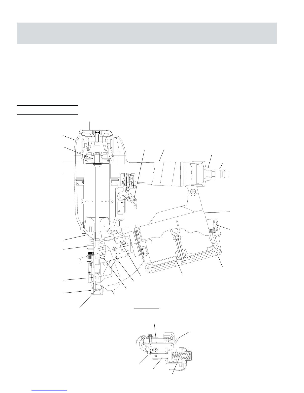
NAME OF PARTS
Feed Spring
Feed Piston
Feeder
Nail Stopper (A)
Nail Guide
Section A-A
Top Cover
Exhaust Cover
Piston
Piston Ring
Driver Blade
Body
Trigger
Cap
Air Plug
Nose
Adjuster
Push Lever
Firing Head (Outlet)
Cover
Feeder
Nail Guide
Knob Nail Holder
Magazine Assembly
Magazine Stopper
Magazine Cover
A
A
Nose Cap

— 7 —
SPECIFICATIONS
Operating pressure 70 – 120 psi (4.9 – 8.3 bar 5 – 8.5 kgf/cm2)
Dimensions 11-1/16" ×11-7/8" ×5-1/8"
Length (without air plug) ×Height ×Width (281 mm ×302 mm ×130 mm)
Weight 5.9 lbs (2.7 kg)
Pin capacity 200 – 300 pins (1 coil)
.052 ft3/cycle at 100 psi
Air consumption (1.5 ltr/cycle at 6.9 bar)
(1.5 ltr/cycle at 7 kgf/cm2)
Air inlet 1/4 NPT Thread
PIN SELECTION
Only pins shown in the Table below can be driven with this Nailer.
NOTE: Use only genuine ET&F pins to assure nail quality and driving ease.
.104"
(2.64 mm)
.240"
(6.1 mm)
1-1/2" (38 mm)
.107"
(2.74 mm)
.252"
(6.4 mm)
2-1/2" (64 mm)
Min. Max.Wire-collated coil pins
.104"
(2.64 mm)
.268"
(6.8 mm)
1-1/4" (32 mm)
.107"
(2.74 mm)
.275"
(7 mm)
2" (50 mm)
Min. Max.
Sheet-collated coil pins

— 8 —
APPLICATIONS
䡬Gypsun wall board to steel studs 12 gauge and lighter
BEFORE OPERATION
Read section titled “SAFETY” (pages 3 – 5).
Make sure of the followings before operation.
WORKING ENVIRONMENT
WARNING
䢇No flammable gas, liquid or other flammable
objects at worksite.
䢇Clear the area of children or unauthorized personnel.
AIR SUPPLY
DANGER
䢇Never use oxygen, combustible gases or any other
bottled gases.
WARNING
䢇Never connect Nailer to pressure which potentially
exceeds 200 psi (13.7 bar 14 kgf/cm2).
䢇Never use non relieving coupler on Nailer.
1. Power source
䡬Use only clean, dry, regulated compressed air as a
power source for this Nailer.
䡬Air compressors used to supply compressed air to this
Nailer must comply with the requirements of the latest
version of ANSI Standard B 19.3 “Safety Standard For
Compressors For Process Industries.”
䡬Moisture or oil in the air compressor may accelerate
wear and corrosion in the Nailer.
Drain daily.
2. Filter-Regulator-Lubricator
䡬Use a regulator with a pressure range of 0 – 120 psi
(0 – 8.3 bar 0 – 8.5 kgf/cm2).
䡬Filter-regulator-lubricator units supply an optimum
condition for the Nailer and extend the Nailer life.
These units should always be used.
Filter ..............The filter removes moisture and dirt
mixed in compressed air.
Drain daily unless fitted with an
automatic drain.
Keep the filter clean by regular
maintenance.
Regulator ......The regulator controls the operating
pressure for safe operation of the Nailer.
Inspect the regulator before operation to
be sure it operates properly.
Lubricator .....The lubricator supplies an oil mist to the
Nailer.
Inspect the lubricator before operation to
be sure the supply of lubricant is adequate.
Use pneumatic tool lubricant.
3. Air hose
Air hose must have a minimum working pressure
rating of 150 psi (10.4 bar 10.6 kgf/cm2) or 150% of the
maximum pressure produced in the system, whichever
is higher.
4. Hose coupling
A female coupler must be on the air hose.
The hose coupling (male plug-female coupler) must
remove all pressure from the Nailer when disconnected.
Never use a non relieving coupler on the Nailer.
5. Air consumption
Using the Air consumption table and the Air
compressor size formula, find a correct compressor size.
ACCESSORIES
WARNING
䢇Accessories other than those shown below can
lead to malfunction and resulting injuries.
STANDARD ACCESSORIES
1Eye protector 1
2Allen wrench for M6 screw 1
3Allen wrench for M5 screw 1
4Allen wrench for M4 screw 1
5Oil feeder 1
6Nose cap 1
24
3
1
Compressor Side
Nailer Side
Filter
Lubricator
Regulator
56

— 9 —
Air consumption table
Air compressor size formula
Amount of air required
=number of Nailers
×average pins driven each minute per Nailer
×air consumption at given air pressure
×safety factor (always 1.2)
Example: 2 Nailers operating at 100 psi driving 30 pins
per minute
Amount of air required
=2 ×30 ×.052 (1.5) ×1.2
=3.7 CFM (ft3/min) (108 ltr/min)
After making the calculations as shown above, you
should find a compressor providing 3.7 CFM of air that
is required.
LUBRICATION
It is important that the Nailer be properly lubricated.
Without proper lubrication, the Nailer will not work
properly and parts will wear prematurely.
䡬Use pneumatic tool lubricant.
Do not use detergent oil or additives. These lubricants
will harm the O-rings and other rubber parts. This will
cause the Nailer to malfunction.
䡬Filter-regulator-lubricator units should always be used.
Keep the lubricator filled with pneumatic tool lubricant.
䡬If a lubricator is not available, supply a few drops
(approximately 2 cc (.12 in3)) of pneumatic tool
lubricant into the air plug on the Nailer twice a day.
COLD WEATHER CARE
䡬Do not store the Nailer in a cold weather environment.
Keep the Nailer in a warm area until beginning the
work.
䡬If the Nailer is already cold, bring it in a warm area and
allow the Nailer to warm up before use.
1Reduce the air pressure to 64 psi (4.4 bar
4.5 kgf/cm2).
2Remove all pins from the Nailer.
3Connect the air hose and free-fire (blank-fire) the
Nailer.
The lowered air pressure will be enough to free-fire
the Nailer.
Slow speed operation tends to warm up the
moving part.
CAUTION
䢇Do not free-fire the Nailer at high pressure.
TESTING THE NAILER
DANGER
䢇Always wear eye protector.
WARNING
䢇Never use Nailer unless push lever is operating
properly.
Before actually beginning work, test the Nailer by using
the check list below. Conduct the tests in the following
order.
If abnormal operation occurs, stop using the Nailer and
contact a ET&F authorized service center immediately.
(1) DISCONNECT AIR HOSE FROM NAILER.
REMOVE ALL PINS FROM NAILER.
䡺ALL SCREWS MUST BE TIGHTENED.
If any screws are loose, tighten them.
䡺THE PUSH LEVER AND TRIGGER MUST MOVE
SMOOTHLY.
psi 80 90 100
Operating pressure (bar) (5.5) (6.2) (6.9)
(kgf/cm2) (5.6) (6.3) (7)
Air consumption ft3/cycle .042 .045 .052
(ltr/cycle) (1.2) (1.3) (1.5)
Trigger
Push Lever
Do not
connect
air hose

— 10 —
Do not pull
Trigger
Depress Push Lever
Pull Trigger
(2) Adjust the air pressure to 70 psi (4.9 bar 5 kgf/cm2).
Connect the air hose.
Do not load any pins in the Nailer.
䡺THE NAILER MUST NOT LEAK AIR.
Hold the Nailer downward and pull the trigger.
䡺THE NAILER MUST NOT OPERATE.
(3) With finger off the trigger, depress the push lever
against the workpiece.
䡺THE NAILER MUST NOT OPERATE.
(4) Without touching the trigger, depress the push lever
against the workpiece.
Pull the trigger.
䡺THE NAILER MUST OPERATE
(5) If no abnormal operation is observed, you may load
pins in the Nailer.
Drive pins into the workpiece that is the same type to
be used in the actual application.
䡺THE NAILER MUST OPERATE PROPERLY.
ADJUSTING AIR PRESSURE
WARNING
䢇Do not exceed 120 psi (8.3 bar 8.5 kgf/cm2).
Adjust the air pressure at recommended operating
pressure 70 – 120 psi (4.9 – 8.3 bar 5 – 8.5 kgf/cm2)
according to the length of pins and the thickness of steel
substrate workpiece.
The correct air pressure is the lowest pressure which will
do the job. Using the Nailer at a higher than required air
pressure unnecessarily over stresses the Nailer.
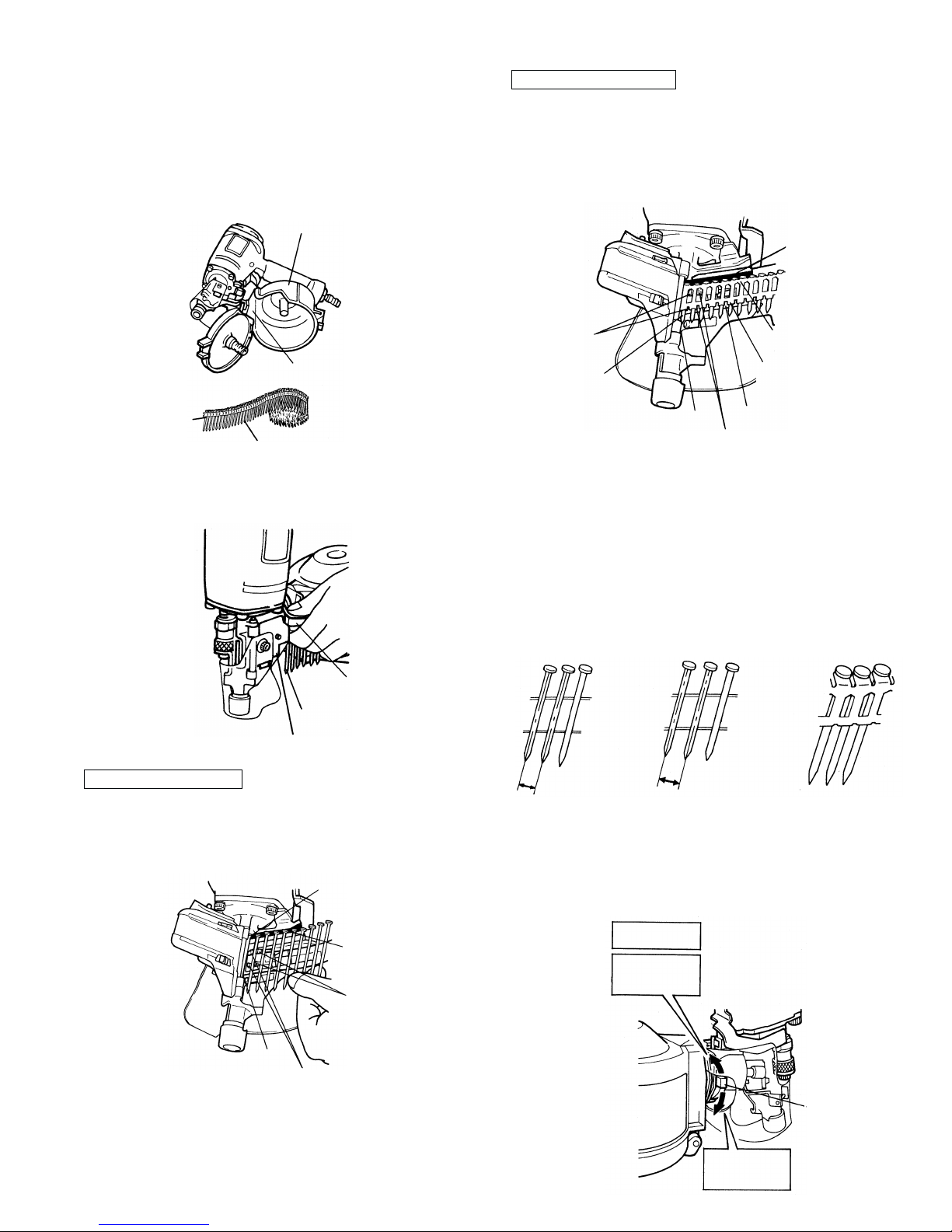
LOADING PINS
WARNING
䢇When loading pins into Nailer,
1) do not pull trigger;
2) do not depress push lever; and
3) keep Nailer pointed downward.
(1) Press the magazine stopper and open the magazine
cover.
(2) Adjust the position of the nail holder according to the
pin length.
The pin will not feed smoothly if the nail holder is not
correctly adjusted.
1Turn the nail holder about 90 degrees
counterclockwise.
2Move the nail holder up and down to align the top
of the nail holder with a mark on the holder shaft in
accordance with the length of the pins being used.
3Turn the nail holder 90 degrees clockwise until you
hear "click".
Magazine Cover
Magazine Stopper
Nail Holder
Nail Holder Holder Shaft
Holder Shaft
1-1/4" (32 mm)
1-1/2" (38mm)
1-3/4" and 2"
(45,50mm)
Nail Holder
Top of the Nail
Holder
— 11 —
Sheet-collated
pins
8mm pitch
wire-collated
pins
Changeover
lever
6mm pitch
wire-collated
pins
Magazine Opening
First Pin
Magazine
Pin
Knob
Nail Guide
First Pin
First pin
Guide slot 1
Feed pawl 2
Feed pawl 1
Ejection port
NOTE: Before loading pins in the magazine, adjust the
nail holder. If the magazine cover is forcibly closed
without adjusting the nail holder correctly, the nail
holder may be damaged.
(3) Place the pin coil in the magazine.
Insert the first pin into the magazine opening.
(4) Close the magazine cover.
(5) Grip the nail guide and knob with finger.
Press the knob down and swing the nail guide open.
For wire-collated pins
The heads of the row of pins are inserted at guide slot 1
(the upper slot).
The first pin is placed in the ejection port with the second
pin between feed pawl 1and feed pawl 2.
For sheet-collated pins
The heads of the row of pins and the upper extent of the
collating sheet are inserted at guide slot 2(the lower
slot). The lower extent of the collating sheet is inserted at
the sheet guide slot.
The first pin is placed in the ejection port with the second
pin between feed pawl 1and feed pawl 2.
(6) Closing the nail guide
Grip the nail guide and knob with the fingers. While
depressing the knob of the nail guide, rotate the nail
guide to the right until it is completely closed.
(7) Setting the changeover lever
This nailer, as shown in the figure, is able to accommo-
date 6mm pitch wire-collated pins, 8mm pitch wire-
collated pins and sheet-collated pins.
As shown in the diagram, according to the type of pin
used, rotate the changeover lever in the direction of
the arrow until it stops.
If the pitch of the pin to be used is not known, it can be
confirmed by comparing the pins themselves to a
diagram affixed to the reverse side of the magazine.
Guide slot 2
Upper extent of
the collating sheet
Lower extent of
the collating sheet
Sheet guide slot
Feed pawl 2
Ejection port
First pin
Feed pawl 1
6 mm pitch wire-
collated pins
8 mm pitch wire-
collated pins
Sheet-collated
pins
8 mm6 mm
— 12 —
NOTE: Care is advised in the following cases since the
nail guide may not close or pins may not feed
properly:
• Pins and collating sheet are not inserted to the
prescribed position
• Pins rise off of the guide surface
• Collating wire of the pins or the like is deformed
• Changeover lever position is not set according to
the collating system of the pins
(8) Lock the knob completely.
NAILER OPERATION
Read section titled “SAFETY”(pages 3 – 5).
DANGER
䢇Always wear eye protector which conforms to
ANSI Z87.1 specifications.
WARNING
䢇Never point Nailer toward yourself or anyone else.
䢇Never carry with finger on trigger.
Remove finger from trigger when not driving pins.
䢇Never place your hands or feet closer than 8 inches
(200 mm) from firing head when using.
䢇Do not drive pins on top of other pins or with
Nailer at too steep of an angle; pins can ricochet
and hurt someone.
䢇In order to avoid double fire or unwanted ejection
of a nail due to bouncing of the Nailer.
1) do not push Nailer on workpiece with strong
force;
2) take Nailer away from workpiece using recoil;
3) release trigger quickly when performing trigger
fire.
䢇Do not drive pins near corners and edges of
workpiece. Pins can be driven through or away
from workpiece and hit someone.
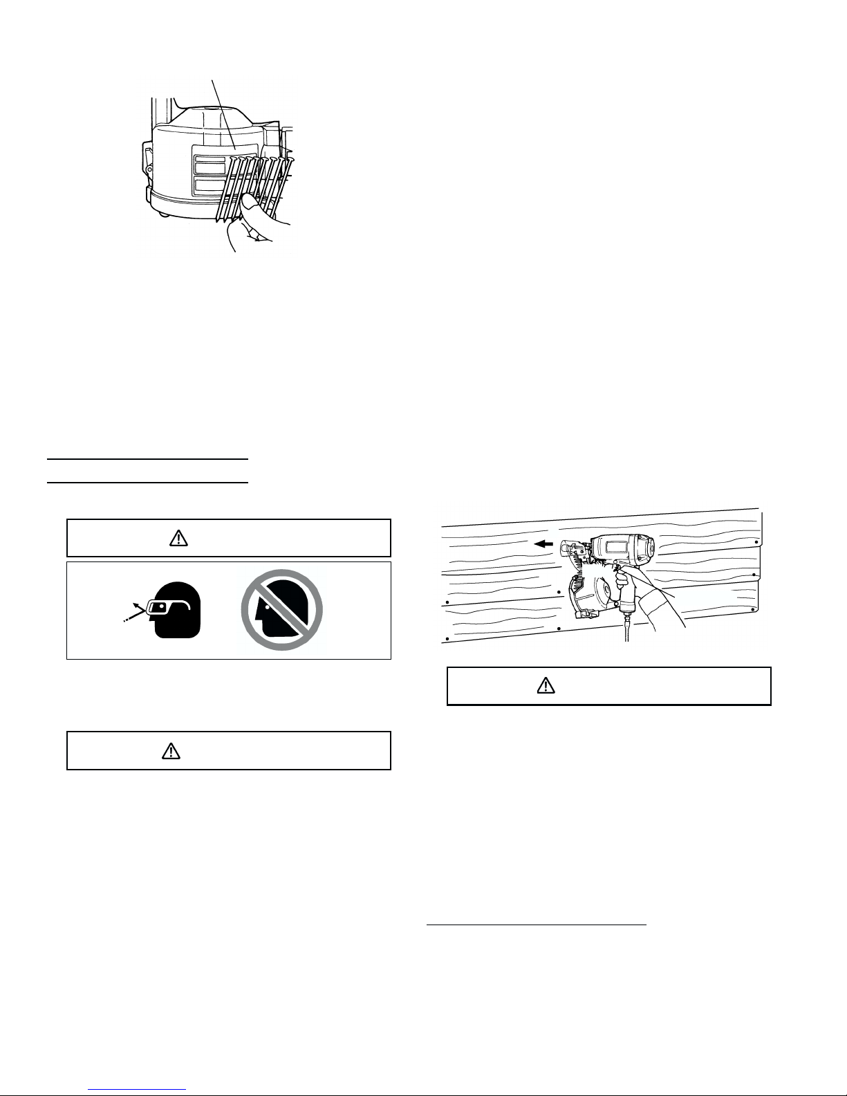
䢇Never drive pins from both sides of a wall at the
same time. Pins can be driven into and through the
wall and hit a person on the opposite side.
䢇Never use Nailer which is defective or operating
abnormally.
䢇Do not use Nailer as hammer.
䢇Disconnect air hose from Nailer when:
1) it is not in use;
2) leaving work area;
3) moving it to another location; and
4) handing it to another person.
This nailer has a SEQUENTIAL TRIP MECHANISM.
METHOD OF OPERATION
This Nailer is equipped with the push lever and does not
operate unless the push lever is depressed (upward
position).
To drive pins with this nailer:
1Position the outlet on the workpiece with finger off the
trigger.
2Depress the push lever firmly until it is completely
depressed.
3Pull the trigger to drive a pin.
4Remove finger from the trigger.
To drive another pin, move the Nailer along the
workpiece and repeat this procedure.
WARNING
䢇Keep your finger off the trigger except during
fastening operation, because serious injury could
result if the push lever accidentally contacts you or
others in work area.
䢇Keep hands and body away from the discharge
area. The nailer with contact trip mechanism may
bounce from the recoil of driving a fastener and
unwanted subsequent fastener may be driven,
possibly causing injury.
䢇Some types of loaded pins can spark out of the
muzzle during a pin driving operation. Exericise
caution!
THE SEQUENTIAL TRIP MECHANISM (SINGLE SHOT
PARTS) is for use where precision fastener placement is
desired and must be operated in accordance with the
following “Method of Operation”.
You must first depress the push lever (upward posi-
tion) where you want to drive a pin and then pull the
trigger. After the each pin is driven, completely release
the trigger and lift the tool off the work surface. The
SEQUENTIAL TRIP MECHANISM may reduce the
Label showing the pitch of pins
Trigger
2
3
\

— 13 —
possibility of bodily injury to you or others in the work
area. This is because it is less likely to drive an un-
wanted pin if you keep the trigger pulled and acciden-
tally bump the push lever against yourself or others.
NOTE:
䢇Always handle pins and package carefully.
If dropped, the collated pins may break or come loose.
In such cases, do not use the pins because, if used in
that condition, pin feed may become faulty and result
in missed pins or jamming of the pins.
䢇After fastening:
1) disconnect air hose from the Nailer;
2) remove all pins from the Nailer;
3) supply a few drops (approximately 2 cc (.12 in3)) of
pneumatic tool lubricant into the air plug on the
Nailer; and
4) open the petcock on the air compressor tank to
drain any moisture.
ADJUSTING THE FASTENING
DEPTH
To assure that each pin penetrates to the same depth, be
sure that:
1) the air pressure to the Nailer remains constant
(regulator is installed and working properly), and
2) the Nailer is always held firmly against the workpiece.
If pins are driven too deep or shallow into the workpiece,
adjust the nailing in the following order.
1DISCONNECT AIR HOSE FROM NAILER
2If pins are driven too deep, turn the adjuster to the
shallow side.
Adjustments are in half-turn increments.
If pins are driven too shallow, turn the adjuster to the
deep side.
Adjuster
Disconnect
air hose
1 5
Too Deep Turn Adjuster Flush
3Stop turning the adjuster when a suitable position is
reached for a fastening test.
4Connect the air hose.
ALWAYS WEAR EYE PROTECTOR.
Perform a fastening test.
5DISCONNECT AIR HOSE FROM NAILER.
6Choose a suitable position for the adjuster.
CHANGING THE EXHAUST
DIRECTION
The direction of the exhaust vent can be changed by
turning the top cover.
CUTTING OFF THE SHEET
Tear off the output sheet in the direction of the arrow
when using the sheet collated pins.
Too Shallow Turn Adjuster Flush
Exhaust Vent
Top Cover
— 14 —
MAINTENANCE
NOTE:
The information contained in this Manual is designed to assist you in the safe maintenance of
the Nailer.
Some illustrations in this Manual may show details or attachments that differ from those on
your own Nailer.
MAINTENANCE AND INSPECTION
Read section titled “SAFETY” (pages 3 – 5).
WARNING
䢇Disconnect air hose and remove all pins from
Nailer when:
1) doing maintenance and inspection; and
2) clearing a jam.
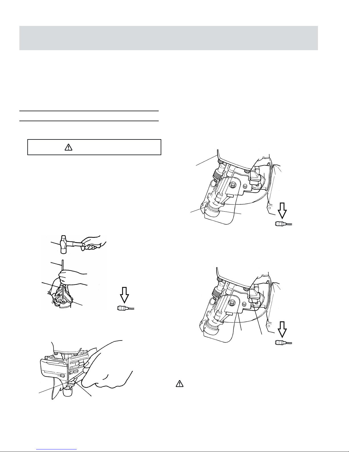
1. Clearing a jam
Remove a jammed pin in the following order :
1DISCONNECT AIR HOSE.
2Open the nail guide.
3Insert a rod into the outlet.
Tap the rod with a hammer.
4Remove the jammed pin with a slotted screw
driver.
5Cut the deformed collated wire with nippers.
Correct the deformation.
6In case of frequent jam, contact an authorized
service center.
2. Inspecting the push lever
1DISCONNECT AIR HOSE.
2Clean the push lever sliding part.
Lubricate it with pneumatic tool lubricant.
3. Inspecting the feeders
1DISCONNECT AIR HOSE.
2Clean the knob sliding part.
Lubricate it with pneumatic tool lubricant.
3Open the nail guide and remove dust.
Lubricate the sliding groove of the feeder and
shafts.
CAUTION
䢇Check that nail stopper (A) and nail stopper (B) slide
smoothly by pushing them with finger.
If not smooth, pins can be driven at an irregular angle
and hurt someone.
Hammer
Rod
Outlet
Nail Guide
Disconnect
air hose
1
Slotted Screw Driver
Pin
Nose
Push
Lever Lubricate
Disconnect
air hose
1
Knob
Nail
Guide
Disconnect
air hose
1

— 15 —
4Lubricate the feeding surfaces of the nose and the
nail guide after cleaning.
This promotes smooth operation and prevents rust.
4. Inspecting the magazine
1DISCONNECT AIR HOSE.
2Clean the magazine. Remove dust or wooden tips
which may have accumulated in the magazine.
5. Storing
䡬When not in use for an extended period, apply a thin
coat of the lubricant to the steel parts to avoid rust.
䡬Do not store the Nailer in a cold weather environment.
Keep the Nailer in a warm area.
䡬When not in use, the Nailer should be stored in a warm
and dry place.
Keep out of reach children.
6. WARNING LABEL
Change the WARNING LABEL if missing or damaged.
A new WARNING LABEL is available from an
authorized service center.
7. Maintenance chart (See page 16)
8. Operator troubleshooting (See page 16)
SERVICE AND REPAIRS
WARNING
䢇Only service personnel trained by ET&F, distributor
or employer shall repair the Nailer.
䢇Use only parts supplied or recommended by ET&F
for repair.
All quality Nailers will eventually require servicing or
replacement of parts because of wear from normal use.
NOTE:
Specifications are subject to change without any
obligation on the part of ET&F.
Nail guide
Nail Stopper (B)
Nose Feeder
Shaft
Nail Stopper (A)
Warning
Label

— 16 —
Maintenance chart
ACTION WHY HOW
Drain air line filter daily. Prevent accumulation of moisture Open manual petcock.
and dirt.
Keep lubricator filled. Keep the Nailer lubricated. Fill with pneumatic tool lubricant.
Clean filter element — then blow Prevent clogging of filter with dirt. Follow manufacturer’s instructions.
air through filter in direction
opposite to normal flow.
Clean magazine and feeder Prevent a jam. Blow clean daily.
mechanism.
Keep push lever working properly. Promote operator safety and Blow clean daily.
efficient Nailer operation.
Lubricate the Nailer after nailing. Extend the Nailer life. Supply 2 – 3 drops of lubricant
into the Nailer.
Drain air compressor. Keep the Nailer operated properly. Open petcock on air compressor tank.
PROBLEM
Nailer operates, but no pin is driven.
Operator troubleshooting
Most minor problems can be resolved quickly and easily using the table below.
If problems persist, contact an authorized service center for assistance.
CHECK METHOD CORRECTION
Check for a jam. Clear a jam per page 14.
Check function of feeder per Clean and lubricate.
page 14.
Check for proper pins. Use only recommended pins.
Check air pressure. Increase air pressure. (Do not
exceed 120 psi (8.3 bar 8.5 kgf/cm2))
——— Use pneumatic tool lubricant.
Driver blade worn? Contact ET&F for replacement.
Piston ring worn or damaged?
Check air pressure. Reduce air pressure.
(Adjust 70 – 120 psi)
Check for proper pins. Use only recommended pins.
Check function of nail feeder per Clean and lubricate.
page 14.
——— Use pneumatic tool lubricant.
Check position of nail holder in Adjust nail holder to proper position.
magazine per page 10.
Piston ring cut or heavily worn? Contact ET&F for replacement.
Check for proper pins. Use only recommended pins.
Driver blade worn? Contact ET&F for replacement.
Check inside diameter of air hose. Use larger air hose.
Weak drive.
Slow to cycle.
Drives too deep.
Skipping pins. Intermittent feed.
Drives properly during normal
operation, but does not drive fully
at faster fastening speeds.
Pins jam.
Driven pin is bent.

— 17 —

— 18 —

— 19 —
1 610-949755 Hex. Socket Hd. Bolt M6×16 1
2 610-880515 Plate 1
3 610-880514 Top Cover 1
4 610-878854 Hex. Socker.Hd. Bolt (W/Flange) M6×25 4
5 610-882158 Exhaust Cover 1
6 610-878919 Gasket (B) 1
7 610-878912 Spring 1
8 610-878913 O-Ring (I.D 38.5) 1
9 610-878911 Head Valve 1
10 610-878372 O-Ring (I.D 52.6) 3
11 610-878918 Head Valve Rubber 1
12 610-878915 Exhaust Valve Rubber 1
13 610-880513 Retaining Ring 1
14 610-874104 Cylinder O-Ring (I.D 68.3) 1
15 610-880512 Cylinder Plate 1
16 610-878961 O-Ring 1
17 610-880735 Cylinder 1
18 610-878931 Piston Ring 1
19 610-880127 O-Ring 1
20 610-880730 Piston (H) 1
21 610-955479 Retaining Ring (E-Type) For D6 Shaft 1
22 610-881006 Body Ass’y 1
23 610-878933 Piston Bumper 1
24 610-874436 O-Ring (P-4) 1
25 610-880121 Washer 1
26 610-880731 Nose 1
27 610-993068 Nylock High Tension Bolt M7×20 4
28 610-949685 Roll Pin D3×20 1
29 610-878339 Needle Roller 1
30 610-949770 Roll Pin D4×14 1
31 610-878132 Feeder Arm 1
32 610-878340 Feeder Spring 1
33 610-880140 Feeder 1
34 610-876676 Safety Spring 1
35 610-880733 Pushing Lever (B) 1
36 610-880497 Nail Guide Shaft 1
37 610-881974 Adjuster (A) 1
38 610-982454 Spring (C) 2
39 610-959155 Steel Ball D3.97 2
40 610-880130 Pushing Lever (A) 1
41 610-880081 Washer 1
42 610-949657 Hex. Socket Hd. M6×12 1
43 610-881768 Grip Tape (A) 1
44 610-880407 Tape 2
45 610-880183 O-Ring (I.D 37.2) 1
46 610-883590 Cap 1
47 591 Air Plug NPT1/4 1
48 610-880734 Machine Screw (W/Washers) M5×25 1
49 610-949864 Roll Pin D3×22 1
50 610-949865 Roll Pin D3×28 2
51 610-881779 Trigger (A) 1
52 610-881771 Trigger Pin 1
53 610-880361 Pushing Lever Guide 1
54 610-877699 Head Valve O-Ring (I.D 16.8) 1
55 610-878881 Valve Bushing (B) 1
56 610-878885 O-Ring (S-18) 1
57 610-981317 O-Ring (S-4) 1
58 610-880672 Valve Piston (B) 1
59 610-878925 O-Ring (I.D 8.8) 2
60 610-878887 O-Ring (I.D 11) 1
61 610-878884 Plunger Spring 1
62 610-881778 Plunger (B) 1
63 610-878888 O-Ring (I.D 1.8) 1
64 610-880671 Valve Bushing (A) 1
65 ————— Label (C) 1
66 610-872645 O-Ring (P-9) 1
67 610-880128 Feed Piston 1
68 610-876796 O-Ring (P-22) 1
69 610-877144 Feed Spring 1
70 610-880129 Shift Lever 1
71 610-877827 Feed Piston Cover (A) 1
72 610-877713 Feed Piston Cover 1
73 610-949819 Hex. Socket Hd. Bolt M5×10 2
74 610-877479 Magazine Bushing 1
75 610-877360 Magazine Bushing 1
76 610-877371 Nylon Nut M5 1
77 610-880133 Magazine 1
78 610-872971 Retaining Ring (E-Type) For D3 Shaft 2
79 610-877149 Stopper Spring 1
80 610-880146 Magazine Stopper 1
81 610-877150 Stopper Pin 1
82 ————— Label (A) 1
83 610-876465 Nylon Nut M4 1
84 610-880666 Holder Shaft 1
85 610-880398 Ratchet Spring 1
86 610-880665 Nail Holder 1
87 610-880704 Magazine Cover 1
88 610-877152 Hinge Pin 1
89 610-949423 Washer M4 1
90 610-949230 Machine Screw M4×50 1
91 610-880703 Magazine Ass’y 1
92 610-877826 Feeder Shaft Ring 1
93 610-880495 Guide Lock 1
94 610-880446 Spring 1
95 610-880732 Nail Guide 1
96 610-949496 Roll Pin D3×16 1
97 610-880493 Nail Stopper (A) 1
98 610-880494 Stopper Spring 2
99 610-880124 Nail Stopper (B) 1
100 610-880125 Nail Guide Cover 1
101 610-880126 Cover 1
102 610-878614 Nylock Hex. Socket Hd. Bolt M4×81
103 610-878337 Sleeve (B) 1
104 610-880413 Nylock Hex. Socket Hd. Bolt M4×10 1
501 610-880132 Nose Cap (A) 1
502 610-877153 Pneumatic Tool Lubricant 30CC 1
503 610-875769 Eye Protector 1
504 610-944459 Hex. Bar Wrench 5MM 1
505 610-944458 Hex. Bar Wrench 4MM 1
506 610-943277 Hex. Bar Wrench 3MM 1
Code No. Part Name Q’ty
Item
No.
Code No. Part Name Q’ty
Item
No.

111
Code No. C99107062 N
Printed in Japan
29019 Solon Road
Solon, ohio 44139
Table of contents
Popular Nail Gun manuals by other brands


norbar
norbar PneuTorque PTS-52-500 Operator's manual

Campbell Hausfeld
Campbell Hausfeld IronForce IFN35650 operating instructions

Novus
Novus J-102 DA Translation of the original operating instructions
Arrow
Arrow ET200 manual

Paslode
Paslode CF325XP operating manual

Senco
Senco FinishPro 42XP operating instructions


