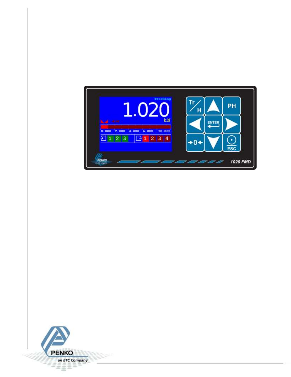
ETC PENKO 1020 FMD User manual

1020 FMD
1
PENKO Engineering B.V.
Your Partner for Fully Engineered Factory Solutions
Quick Start:
1020 FMD

1020 FMD
2
Table of Contents
Introduction......................................................................................................................................3
In the box......................................................................................................................................3
Needed for use .............................................................................................................................3
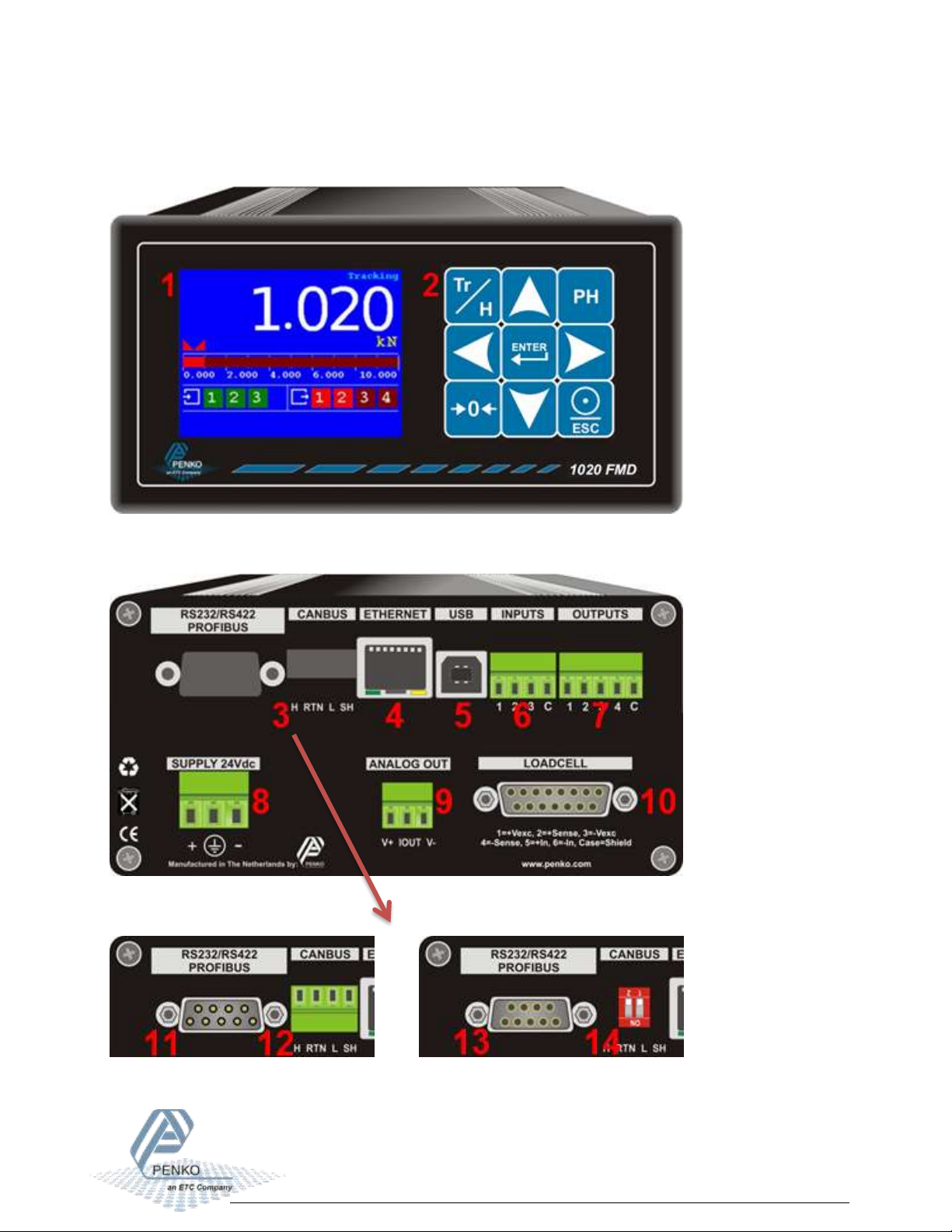
1Overview ...................................................................................................................................4
2Connections ..............................................................................................................................5
2.1 Power supply .....................................................................................................................5
2.2 Load cell.............................................................................................................................6
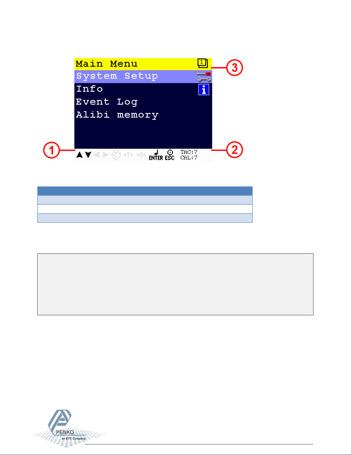
3Display and keypad ...................................................................................................................7
4First use...................................................................................................................................11
5Standard factory settings........................................................................................................20
6Menu structure .......................................................................................................................21

1020 FMD
3
Introduction
The PENKO 1020 FMD is a compact comprehensive Force Measurement Device.
In the box
The box contains the following items:
1 x 10²⁰ FMD device
1 x rubber ring for mounting purpose
2 x clip for mounting purpose
1 x connector for load cell connection
1 x quick start manual
Needed for use
To use the 1020 FMD the following items are needed:
Class 2 or Limited Power Source, rate 18 - 32 VDC, 0.4A@24VDC
Load cell / Torque sensor

1020 FMD
4
1Overview
Option 1: Option 2:

1020 FMD
5
Number
Description
1
TFT display 320 x 240
2
Keypad
3
OPTION: None || Serial + CAN bus || Profibus
4
Ethernet connection
5
USB connection
6
Digital inputs (3)
7
Digital outputs (4)
8
24VDC power supply
9
OPTION: Analog output
10
Load cell connection
11
RS232/RS422 connection
12
CAN bus connection
13
Profibus connection
14
Bus termination for Profibus
2Connections
This chapter describes the power supply and load cell connections of the 1020 FMD.
2.1 Power supply
Power the device using a Class 2 or Limited Power Source, rate 18 –32 VDC, 0.4A@24VDC

1020 FMD
6
2.2 Load cell
Property
Description
Wiring
With sense
Type of sense
Passive
Excitation voltage
5 VDC
Sensitivity
0,1 μV/d
Selectable ranges
1 mV/V | 1,5 mV/V | 2 mV/V | 2,5 mV/V | 3 mV/V
Input voltage @3mV/V
-16 mV to 16 mV
A/D Conversion speed
1600/s
Max. load cell impedance
1200 Ω
Min. Load cell impedance
43,75 Ω
Max. no. of load cells 350 Ω
8
Max. no. of load cells 1000 Ω
22

1020 FMD
7
3Display and keypad
The display contains the following indications:
Number
Description
1
Indicator in stable range [] Zero active [] Range/Interval active
2
Bar graph indication
3
Digital input active indication (3 inputs)
4
Digital output active indication (4 outputs)
5
Measured value
6
Type of value shown on the display (Tracking, Hold, T.I.R, Peak, Valley) *
* Display value
Tracking
Tracking value. The display follows the input signal.
Hold
Hold value. The hold value is stored every time the zero button is pressed in hold
mode, and every time the input, programmed as hold, is high.
Peak
Peak hold value. This is the highest measured value.
Valley
Valley hold value. This is the lowest measured value.
T.I.R.
Total Indicated Readout value. The difference between the peak hold and valley
hold value.
See next page for examples.

1020 FMD
8
Hold function
Peak, Valley and T.I.R. function

1020 FMD
9
The display indications in menu mode:
Number
Description
1
Active buttons for current menu item
2
TAC and CAL code*
3
Menu level
* TAC and CAL code
TAC stands for Traceable Access Code. A number of settings are only available after entering
this code. When these settings are changed, the TAC is incremented with 1.
CAL stands for CALibration code. The calibration settings are only available after entering this
code. When the calibration settings are changed, the CAL is incremented with 1.

1020 FMD
10
The keys have the following functions:
Tracking / Hold
Toggle between Tracking mode and Hold mode.
Peak Hold
Show Peak Hold mode.
Enter / Menu
Adjust levels. Press > 2 seconds to enter configuration menu. In menu mode, press
to confirm setting.
Zero
Press to set tare/zero. Press again to reset tare/zero. In Hold mode, press to set
hold value. In Peak/Valley/T.I.R mode, press to clear the stored value.
Print / Escape
Press to cancel or step back one menu item. Press from start screen to print.
Up / Increase value
From start screen, press to show T.I.R. value on the display.
Down / Decrease value
From start screen, press to show valley hold value on the display.
Left / Change position of cursor
Right / Change position of cursor

1020 FMD
11
4First use
For first use, the following settings are important:
Unit indication
Decimal point position
Step size
Maximum load
Calibration
This chapter describes how to adjust these settings.
Main Menu
From the main screen, press the Enter button for 2 seconds to enter the Main Menu.
Press 2 seconds

1020 FMD
12
Navigate through menu
Use the Up and Down button to navigate through the menus. Use the Enter button to enter a
menu item. Use the Escape button to step back a level.
Up
Down
Open menu
item
Back to
previous level
Edit a value
Use the arrow buttons to edit a value. Select the digit with the Left and Right button. Increase
the value with the Up button. Decrease the value with the Down button. Use the Enter button
to confirm the whole value. Use the Zero button to clear the whole value.
Select
previous digit
Select next
digit
Increase
selected digit
Decrease
selected digit
Confirm
whole value
Clear whole
value

1020 FMD
13
Edit a text
In case a text has to be edited, a keyboard appears on the screen.
Use the arrow buttons to navigate through the keyboard. Use the Enter button to select the
character. Use the Zero button for backspace. Use the Peak-hold button to change the character
set.
Left
Right
Up
Down
Select
character
Backspace
→
→
Change character set

1020 FMD
14
Indicator parameters
The indicator parameters can be set as follows:
Enter the TAC as shown on the right bottom
corner of the screen using the arrow buttons
- apply with the Enter button

1020 FMD
15
Here the Unit, Step size, Decimal point and
Max load can be set
Unit
Set the unit of measurement, for example kN or N. This will be shown everywhere the measured
force is displayed or printed.
Decimal point
Select the position of the decimal point. This setting will be used everywhere the measured
force is displayed or printed.
Available options
000000
00000.0
0000.00
000.000
00.0000
0.00000
Step
Select the step size. This setting defines the scaled parts of the force value. The display value
will be rounded to the nearest value with a valid step size. Available options:

1020 FMD
16
Available options
1
2
5
10
20
50
100
200
Example:
Measured value is 2005 kN.
Step size
Displayed value
1
2005
2
2006
5
2005
10
2010
20
2000
50
2000
100
2000
200
2000
Maxload
Set the force the indicator will use as maximum. If the measured force is higher than the
maximum load, the display will show ======

1020 FMD
17
Calibration
Enter the CAL as shown on the right bottom
corner of the screen using the arrow buttons
- apply with the Enter button

1020 FMD
18
Make sure the load cell or force sensor is not
loaded and is stable before pressing Enter
Make sure the load cell or force sensor is
loaded with the reference weight and is
stable before pressing Enter

1020 FMD
19
Enter the reference weight - apply with the
Enter button
The device is now calibrated
Error codes:
Error code
Description
Solution
CCCCCC
No proper calibration available
Check calibration setting
UUUUUU
Underflow
Check load cell
Check platform construction
OOOOOO
Overflow
Check load cell
Check platform construction
======
Display overflow; Exceed
maximum display value (max.
load)
Reduce load on platform

1020 FMD
20
5Standard factory settings
Description
Display
Value
Your setting
Properties
Name
…
Unit label
kN
Step
1
Decimal point
0,000
Max Load
10,009 kN
Sample Rate
1600/s
Stable condition
Range
0,002 kN
Time
1,00 s
Zero tracking
Range
0,000 kN
Step
0,000 kN
Time
0,00 s
Range / Interval
Range
0 Parts
Max Step
1
Mode
Multi Range
Filter - Overall
Overall Filter
0 dB
Filter - Digital
Digital Filter
Static App.
Cutoff Frequency
1,0 Hz
Frequency
50 Hz
Filter- Display
Filter Range
0,000 kN
Display Filter
0 dB
Display Rate
25 updates/s
Disp.Suppress
0,000 kN
Table of contents
Other ETC Measuring Instrument manuals