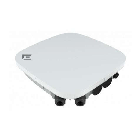
EtherWAN EW75000 Series Assembly instructions

Installation and Setup Guide
EW75000 Hardened Wireless LAN Access Point
FastFind Links
Introduction
Installation
Configuration

All Rights Reserved
Dissemination or reproduction of this document, or its contents, is not authorized except where expressly
permitted. Violators are liable for damages. All rights reserved, for the purposes of patent application or
trademark registration.
Disclaimer of Liability
The information contained in this document is subject to change without notice. EtherWAN is not liable for
any errors or omissions contained herein or for resulting damage in connection with the information
provided in this manual.
All other trademarks are property of their respective owners.
Warranty
For details on the EtherWAN warranty replacement policy, please visit our web site at:
https://kb.etherwan.com/index.php?CategoryID=13
Products Supported by this Manual:
EW75200-0804, EW75200-1304, EW75200-2104, EW75000-08, EW75000-13, EW75000-21

iii
EW75000 Hardened Wireless LAN Access Point
Preface
Audience
This guide is designed for the person who installs, configures, deploys, and maintains the
Ethernet network. This document assumes the reader has moderate hardware, computer, and
Internet skills.
Document Revision Level
This section provides a history of the revision changes to this document.
Revision Document Version
Date Description
A Version 1 12/27/2017
Changes in this Revision
This is first version of this document.
Document Conventions
This guide uses the following conventions to draw your attention to certain information (see
following page).

iv
EW75000 Hardened Wireless LAN Access Point
Safety and Warnings
This guide uses the following symbols to draw your attention to certain information.
Symbol Meaning Description
Note Notes emphasize or supplement important points of the main text.
Tip Tips provide helpful information, guidelines, or suggestions for performing tasks more
effectively.
Warning Warnings indicate that failure to take a specified action could result in damage to the
device, or could result in serious bodily injury.
Electric Shock Hazard
This symbol warns users of electric shock hazard. Failure to take appropriate precautions
such as not opening or touching hazardous areas of the equipment could result in injury or
death.
Abbreviations
The following abbreviations are used throughout this manual.
ABR: Area Border Router
AES: Advanced Encryption Standard
AP: Access Point
BFD: Bidirectional Forwarding Detection
DUT: Device Under Test
EAP: Extensible Authentication Protocol
IKE: Internet Key Exchange
LSA: Link State Announcement
MME: Mesh Made Easy
NAT: Network Address Translation
SSID: Service Set Identifier
SUT: System Under Test
TKIP: Temporal Key Integrity Protocol
WDS: Wireless Distribution System
WPA2: Wireless Protected Access 2
WPS: Wi-Fi Protected Setup
VRF: Virtual Routing and Forwarding
NOTE: The terms “EX75000 series” and “eWAV” are used interchangeably in this manual.

v
EW75000 Hardened Wireless LAN Access Point
Contents
Preface ..................................................................................................................... iii
Changes in this Revision ........................................................................................... iii
Document Conventions ............................................................................................. iii
Safety and Warnings ................................................................................................ iv
Abbreviations ........................................................................................................... iv
Contents ................................................................................................................... v
1 Introduction ........................................................................................................... 7
EW75000 Series Model Reference............................................................................ 8
2 Installation ............................................................................................................. 9
Unpacking the Hardware ........................................................................................... 9
Supplying Power ....................................................................................................... 9
Digital Configuration ................................................................................................ 10
Connect Antennas ................................................................................................... 10
Physical Installation ................................................................................................. 11
Grounding ............................................................................................................... 12
Surge Protection ...................................................................................................... 12
Reset Button ........................................................................................................... 13
LED Status Indicators .............................................................................................. 13
3 Configuration ...................................................................................................... 14
Quick Set ................................................................................................................. 14
Description of Quick Set Modes .............................................................................. 15
Advanced Mode ...................................................................................................... 16
Description of Menu Items ................................................................................. 17
Example: Set Up a Point to Point Link Using QuickSet ............................................ 45
Configure the Access Point................................................................................ 45
Configure the Subscriber Unit ............................................................................ 46
Example: Set Up a Point to Point Link Using Advanced Mode ................................. 47
Configure the Access Point................................................................................ 47
Configure the Subscriber Unit: ........................................................................... 49

vi
EW75000 Hardened Wireless LAN Access Point
Specifications .......................................................................................................... 50
Technology ........................................................................................................ 50
Antenna ............................................................................................................. 50
A.3 Power .......................................................................................................... 50
Wireless ............................................................................................................. 51
A.5 Physical ....................................................................................................... 52
Regulatory Approvals ........................................................................................ 52
Interference Statement ...................................................................................... 53

7
EW75000 Hardened Wireless LAN Access Point
1 Introduction
The eWAV EW75000 series is a family of hardened outdoor wireless access points
(WAP) and client bridges providing high speed wireless connectivity for harsh and
demanding environments. Comprised of high-power, long-range single and
dual-band IEEE 802.11ac MIMO wireless radios with gigabit IEEE802.3at PoE
connectivity, the series is hardened against extreme temperatures and water ingress.
eWAV delivers the power and range (up to 40 kilometers) to wirelessly connect
remote networks, or extend existing networks in an efficient and cost-effective way. It
supports 2.4 GHz 802.11 b/g/n for local device access like laptops, wireless IP
cameras, or mobile devices, and also 5 GHz 802.11ac/a/n for long distance data
transmission. Maximum transmission speeds are up to 300 Mbps on 2.4GHz and 866
Mbps on the 5GHz band.
The series can be used for Point-to-Point (PTP) wireless networks, connecting two
locations together through line of sight (LOS). Typical PTP applications include
building to building connectivity, replacing fiber-optic cable, and wireless failover for
wired connections.
Point-to-Multipoint (PTMP) wireless communication is also supported. PTMP
wireless networks connect access points to multiple locations through both LOS and
non-line-of-sight (NLOS). Some common PTMP applications are: Connecting
multiple buildings, video surveillance systems, and replacing fiber-optic cable.
Installation is greatly simplified by Power-over-Ethernet support, allowing for
mounting in locations where there is no power outlet. Network administrators can
control the transmission power and setting remotely, including bandwidth control and
traffic shaping. Wireless encryption is supported for added security.

8
EW75000 Hardened Wireless LAN Access Point
EW75000 Series Model Reference
Model Image Mode Wireless Modules
EW75200-0804
Access Point 2.4G, 5G (AP)
EW75200-1304
Access Point 2.4G, 5G (AP)
EW75200-2104
Access Point 2.4G, 5G (AP)
EW75000-08
Access Point 5G (AP)
EW75000-13
Subscriber unit 5G (Subscriber)
EW75000-21
Subscriber unit 5G (Subscriber)

9
EW75000 Hardened Wireless LAN Access Point
2 Installation
Unpacking the Hardware
Unpack the items and confirm that no items are missing or damaged. Your package
should include:
One EW75000 series hardened wireless access point (AP) or subscriber unit
Zero, two or four omnidirectional antennas, depending on model
Mounting bracket set
Grounding wire
Quick installation guide
If any item is damaged or missing, notify your authorized EtherWAN representative. Keep
the carton, including the original packing material, in case you need to store the product or
return it.
Supplying Power
All EW75000 series models are PoE Powered Devices, and have no AC or DC power
socket. Power is supplied through an Ethernet cable plugged into the RJ45 port. The
cable must be connected to a switch that supports PoE, or an inline power injector.
Maximum power consumption is 13 watts.
Warning: Do not apply power to the device until all supplied antennas have been
securely attached.
RJ-45 PoE Port

10
EW75000 Hardened Wireless LAN Access Point
Digital Configuration
Use an Ethernet cable to connect a PC to the PoE switch or power injector, and another
cable to connect the switch/injector to the EW75000. Use a web browser to navigate to the
default IP address, and log in.
Note: The PC being used to configure the EW75000 Series must be on the same
subnet as the EW75000. It may be necessary to change the PC’s IP address temporarily.
The default IP address is 192.168.1.20
User name is root, no password.
If you need to reset the switch to its default configuration from a remote location, you will
need to log in with full administrator rights.
Login: administrator
Password: eWAV750o0!
It is highly recommended to change both the root and administrator passwords before
putting the device into regular service.
The Quick Set page will display by default. Select the function mode from the drop-down
menu in the upper right corner. The fields displayed depend on the mode selected.
Alternatively, you can exit the Quick Set page by clicking the “Advanced Mode” tab in the
upper right corner, and going directly to the main screen. See chapter on configuration for
details.
Connect Antennas
The EW75000 is equipped with an internal directional antenna, which provides
long-distance coverage in the direction it is pointing.
Depending on the model, your AP might come with two 5 GHZ and/or two 2.4GHz
antennas. Screw the antennas into the corresponding threaded sockets in the housing.

11
EW75000 Hardened Wireless LAN Access Point
Physical Installation
NOTE: It is recommended to test all wireless devices before final installation. This
includes bench testing, and signal testing of the AP and subscriber unit in the positions
where they will be mounted. Loosely mount AP and subscriber units in the intended
installation spots, and ensure that the transmission signal is strong enough for the
intended application.
This product is designed for outdoor installation on a pole or wall. It is recommended to
install the AP at a height of at least 5 meters (15 feet). Make sure that there are no
obstacles between devices. Mount the AP with the Ethernet port and LED facing down.
A higher mounting position will result in a stronger signal.
Align the four holes on the housing bracket with those on the back face of the housing,
and use the four M5 hex screws to attach the bracket to the housing.
Attach the two brackets with the supplied M8 hex screws as shown in figure below. Make
sure the stop tabs (indicated by red circles in figure) are on the same side as the
arc-shaped slot.
Pole mounting:

12
EW75000 Hardened Wireless LAN Access Point
Slide the two ring clamps into the four vertical slots on the bracket. Wrap the clamps
around the pole, and tighten the side screws so that the clamps are securely held on the
pole.
Wall mounting:
To mount to a wall, use two L-brackets (not supplied), and secure them to the triangular
tabs on the top and bottom of the AP bracket. Make sure the L-brackets used and the wall
itself are strong enough to hold the weight of the device.
Grounding
There are two grounding terminals located on the rear of the housing. Attach the
supplied grounding wire to the housing at either terminal using a screw (not included), and
tighten so that the grounding wire is secure. Attach the other end of the grounding wire to
an electrical ground.
Surge Protection
In areas with high incidence of lightning, it is suggested to install surge protection
devices on the Ethernet cable, such as the PD1041 hardened surge protection device
available from EtherWAN. This will protect the indoor network from damage caused by
electrical surges through the data cable. Check your local electrical codes, and contact
your EtherWAN representative to find out more.
Note that the omnidirectional antennas that come with some models are equipped with
built-in gas discharge tube surge protectors, which can be replaced as needed.

13
EW75000 Hardened Wireless LAN Access Point
Reset Button
There is a reset button located at the
bottom of the housing. To access the
button, remove the protective cap as
shown in the figure on the right.
Power down the device by removing the
Ethernet cable. Plug the cable back in while
pressing and holding the reset button for eight
seconds to reset the device operating system
to its default state.
LED Status Indicators
The unit has 6 green LED indicators, located on the bottom of the housing.
Power: When lit, indicates that device is receiving PoE power.
Ethernet: (Steady on) Indicates the Ethernet port link is up. (Flashing) Indicates data is
being transferred.
2.4G: When lit, indicates 2.4G wireless link connected.
5G: Indicates 5G wireless link connected.
One LED lit indicates low signal strength.
Two LEDs lit indicate medium signal strength.
Three LEDs lit indicate strong signal strength.

14
EW75000 Hardened Wireless LAN Access Point
3 Configuration
Quick Set
Once you have logged in, you will see the Quick Set page. This page provides several
presets that allow for fast configuration of the device. Selecting an operation mode from
the drop-down menu in the upper right corner causes the relevant fields for that setup to be
displayed.
If you do not wish to use Quick Set, click the Advanced Mode tab to navigate to the full
configuration interface. Refer to the section on Advanced Mode for more information.
At the top right of the page, select the operation mode. The modes available will depend on
whether your device is an access point or a subscriber unit.
Access Point Modes
Subscriber Unit Modes

15
EW75000 Hardened Wireless LAN Access Point
Description of Quick Set Modes
The Quick Set mode to be selected will depend on the intended application of the
EW75000. Each mode is roughly described in the table below.
MODE DESCRIPTION
CAP Controlled Access Point, an AP that will be managed by a
CAPsMAN server. (CAPsMAN is not supported on all models)
CPE
Short for "Customer Premises Equipment", this term is used to mean
a "wireless station". As a client device, it connects to a (wireless)
network, like your computer would, but doesn't create its own (like an
access point).
PTP Bridge AP
To transparently interconnect two remote locations together in the
same network, set one device to this mode, and the other device to
the next (PTP Bridge CPE) mode.
PTP Bridge CPE
To transparently interconnect two remote locations together in the
same network, set one device to this mode, and the other device to
the previous (PTP Bridge AP) mode.
WISP AP Similar to the Home AP mode, but provides more advanced options
and uses industry standard terminology, like SSID and WPA.
Home AP This is the default Access Point configuration for most home users. It
provides fewer options and simplified terminology.
Home AP Dual
Dual band devices (2GHz/5GHz). This is the default Access Point
configuration for most home users. It provides fewer options and
simplified terminology.
To create a basic Point to Point link, use the PTP Bridge AP and PTP Bridge CPE Quick
Set modes.

16
EW75000 Hardened Wireless LAN Access Point
Advanced Mode
In Advanced Mode, menu items are arranged on the left side of the page. Items with a
small black arrow can be expanded to view its sub-menu. When a menu item is selected,
the corresponding layout showing relevant fields and tabs will display in the main working
area in the center of the page. Some items in the working area have the following icons to
their left:
- Enable current item
- Disable current item
- Remove current item
At the bottom of the left-side menu items are undo and redo buttons, which can be used to
quickly undo any changes to the configuration.
Also at the bottom, the Hide Passwords button will prevent passwords from displaying on
the screen when you enter them in a field.

17
EW75000 Hardened Wireless LAN Access Point
Description of Menu Items
Wireless
The wireless page allows for the easy management of wireless connections. Functions
are organized by tab layers across the top.
Interfaces – Add, delete and manage wireless interfaces, and analyze interfaces with
various tools. Clicking on an item in the table opens the detail page for that wireless
interface.
Nstreme Dual – Nstreme Dual is a proprietary wireless protocol compatible only with other
eWAV devices. It allows for fast data exchange and more robust channels, in point-to-point
and point-to-multipoint setups.
Access List – Used to restrict allowed connections from other devices, and to control
connection parameters.
Registration – This is a read-only table that shows information about currently connected
clients. It is used only by Access Points.
Connect List – Connect list is an ordered list of rules used to assign priority and security
settings to connections with remote access points, and to restrict allowed connections.
Each rule in connect-list is attached to specific wireless interface, specified in the interface
property of that rule (this is unlike an access list, where rules can apply to all interfaces).
Security Profiles – This page is used to configure security parameters, including RADIUS,
EAP, and static keys.
Interfaces
Both physical and virtual interfaces are managed on this page.

18
EW75000 Hardened Wireless LAN Access Point
Interface – Shows current interfaces. Clicking on an item in the table opens the detail page
for that interface.
Interface List – Allows for the defining of interface sets for easier interface management in
firewalls.
Ethernet – Click an Ethernet connection shown in the table to view or modify its
parameters.
VLAN – Add new and view existing VLANs. 802.1Q VLANs and Q-in-Q are supported.
Bridge
Ethernet-like networks (Ethernet, Ethernet over IP, IEEE802.11 in ap-bridge or bridge
mode, WDS, VLAN) can be connected together using MAC bridges. The bridge feature
allows the interconnection of hosts connected to separate LANs (using EoIP,
geographically distributed networks can be bridged as well if any kind of IP network
interconnection exists between them) as if they were attached to a single LAN. As bridges
are transparent, they do not appear in traceroute list, and no utility can make a distinction
between a host working in one LAN and a host working in another LAN if these LANs are
bridged (depending on the way the LANs are interconnected, latency and data rate
between hosts may vary).
Bridge – In the Bridge sub-tab, new bridges can be created, and existing bridges can be
managed.
Ports – This page shows which ports are assigned to which bridges. Click Add New to
add a new port to a bridge (Bridge must have already been created).
Filters – The bridge firewall implements packet filtering and thereby provides security
functions that are used to manage data flow to, from and through bridge. Filters can be
configured with one of three predefined chains:
input: filters packets, where the destination is the bridge (including those packets that
will be routed, as they are destined to the bridge MAC address anyway)
output: filters packets, which come from the bridge (including those packets that has
been routed normally)
forward: filters packets, which are to be bridged (note: this chain is not applied to the
packets that should be routed through the router, just to those that are traversing
between the ports of the same bridge)
NAT – Bridge network address translation provides ways for changing source/destination
MAC addresses of the packets traversing a bridge. It has two built-in chains:
srcnat: used for "hiding" a host or a network behind a different MAC address. This
chain is applied to the packets leaving the router through a bridged interface
dstnat: used for redirecting some packets to other destinations
Hosts – This is a read-only page that shows list of hosts connected to a bridge and their
corresponding MAC addresses.

19
EW75000 Hardened Wireless LAN Access Point
PPP
Point-to-Point Protocol (PPP) is a Layer 2 communications protocol used to establish a
direct connection between two nodes. It provides Authentication via the Password
Authentication Protocol (PAP), the Challenge-Handshake Authentication Protocol (CHAP),
and Microsoft’s version (MS-CHAP v1/v2).
Interface – All PPP client and server configurations are added and managed on this page.
Click the Add New button and select the desired client or server setup from the drop-down
list.
PPPoE Servers – PPPoE is an extension of the standard Point to Point Protocol (PPP).
The difference between them is expressed in transport method: PPPoE employs Ethernet
instead of serial modem connection.
Secrets – This is the PPP User Database, which stores PPP user access records with
PPP user profile assigned to each user.
Profiles – PPP profiles are used to define default values for user access records. Settings
in the Secret sub-tab override corresponding profile settings except that single IP
addresses always take precedence over IP pools when specified as local-address or
remote-address parameters.
Active Connections – This is a read-only page that displays active PPP and PPPoE
connections.
L2TP Secrets – L2TP is a secure tunnel protocol for transporting IP traffic using PPP.
L2TP encapsulates PPP in virtual lines that run over IP, Frame Relay and other protocols.
L2TP incorporates PPP and MPPE (Microsoft Point to Point Encryption) to make
encrypted links. The purpose of this protocol is to allow the Layer 2 and PPP endpoints to
reside on different devices interconnected by a packet-switched network. With L2TP, a
user has a Layer 2 connection to an access concentrator - LAC (e.g., modem bank, ADSL
DSLAM, etc.), and the concentrator then tunnels individual PPP frames to the Network
Access Server - NAS. This allows the actual processing of PPP packets to be separated
from the termination of the Layer 2 circuit. From the user's perspective, there is no
functional difference between having the L2 circuit terminate in a NAS directly or using
L2TP.

20
EW75000 Hardened Wireless LAN Access Point
Mesh
The EW75000 series uses HWMP+ for wireless mesh networks. It is based on Hybrid
Wireless Mesh Protocol (HWMP) from the IEEE 802.11 draft standard. It can be used
instead of (Rapid) Spanning Tree protocols in mesh setups to ensure loop-free optimal
routing.
However, the HWMP+ protocol is not compatible with IEEE 802.11 based standard HWMP.
Note that the distribution system used for the network does not need to be Wireless
Distribution System (WDS). HWMP+ mesh routing supports not only WDS interfaces, but
also Ethernet interfaces inside the mesh.
Mesh – Add new and manage existing mesh interfaces on this page. Use the Mesh
Traceroute command to determine which paths are being used for routing.
Ports – Add and configure mesh interface ports on this page.
FDB – The FDB (Forwarding Database) page is a read-only page that displays information
about local MAC addresses, non-mesh nodes reachable through local interface and direct
mesh neighbors.
IP
The IP menu is subdivided into 21 submenus, which can be expanded and collapsed by
clicking the small black triangle on the right of the IP button. The function of each submenu
item is described below.
ARP
Address Resolution Protocol is used to map OSI level 3 IP addresses to OSI level 2 MAC
addresses. The Router has a table of currently used ARP entries. Normally the table is
built dynamically, but to increase network security, it can be partially or completely built
statically by means of adding static entries.
Other manuals for EW75000 Series
2
This manual suits for next models
6
Table of contents
Other EtherWAN Wireless Access Point manuals