manuals.online logo
Brands
  1. Home
  2. •
  3. Brands
  4. •
  5. EtherWAN
  6. •
  7. Wireless Access Point
  8. •
  9. EtherWAN EW75000 Series User manual

EtherWAN EW75000 Series User manual

Copyright 2017 EtherWAN Systems, Inc.
Page 1
All Rights Reserved
EW75000
11/10/2017 W70G-EW75000Q1
EW75000 Hardened Wireless LAN Access Point / Subscriber Unit
Installation Guide
1
Unpacking
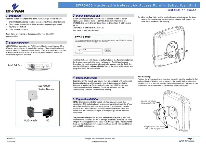
Open the carton and unpack the items. Your package should include:
One EW75000 hardened wireless access point (AP) or subscriber unit
Zero, two or four omnidirectional antennas, depending on model
Mounting bracket set
Grounding wire and screw
Quick installation guide
If any items are missing or damaged, notify your EtherWAN
representative.
2
Supplying Power
All EW75000 series models are PoE Powered Devices, and have no AC or
DC power socket. Power is supplied through an Ethernet cable plugged
into the RJ45 port (shown in figure below). The cable must be connected
to a switch that supports PoE, or an inline power injector. Maximum
power consumption is 13 watts.
3
Digital Configuration
Use an Ethernet cable to connect a PC to the PoE switch or power
injector, and another cable to connect the switch/injector to the
EW75000. Use a web browser to navigate to the default IP address, and
log in.
The default IP address is 192.168.1.20
User name is root, no password.
The Quick Set page will display by default. Select the function mode from
the drop-down menu in the upper right corner. The fields displayed
depend on the mode selected. Alternatively, you can exit the Quick Set
page by clicking the “Advanced Mode” tab in the upper right corner, and
going directly to the main screen.
4
Connect Antennas
Depending on the model, your device may be equipped with an internal
directional antenna, which provides long-distance coverage in the
direction it is pointing. Some models include two 5 GHZ and/or two
2.4GHz omnidirectional antennas. Screw the antennas into the
corresponding threaded sockets in the housing.
5
Physical Installation
NOTE: It is recommended to test all wireless devices before final
installation. This includes bench testing, and signal testing of the AP and
subscriber unit in the positions where they will be mounted. Loosely
mount AP and subscriber units in the intended installation spots, and
ensure that the transmission signal is strong enough for the intended
application.
This product is designed for outdoor installation on a pole or wall. It is
recommended to install the AP at a height of at least 5 meters (15 feet).
A higher mounting position will result in a stronger signal. Make sure that
there are no obstacles between devices. Mount the AP with the Ethernet
port and LED facing down.
1. Align the four holes on the housing bracket with those on the back
face of the housing, and use the four M5 hex screws to attach the
bracket to the housing.
2. Attach the two brackets with the supplied M8 hex screws as shown in
figure below. Make sure the stop tabs (indicated by dotted circles in
figure) are on the same side as the arc-shaped slot.
Pole mounting:
Slide the two ring clamps into the four vertical slots on the bracket. Wrap
the clamps around the pole, and tighten the side screws so that the
clamps are securely held on the pole.
Wall mounting:
To mount to a wall, use two L-brackets (not supplied), and secure them
to the triangular tabs on the top and bottom of the AP bracket. Make sure
the L-brackets used and the wall itself are strong enough to hold the
weight of the device.
RJ-45 PoE Port
Copyright 2017 EtherWAN Systems, Inc.
Page 2
All Rights Reserved
EW75000
11/10/2017 W70G-EW75000Q1
EW75000 Hardened Wireless LAN Access Point / Subscriber Unit
Installation Guide
6
Grounding
There are two grounding terminals located on the rear of the housing.
Attach the supplied grounding wire to the housing at either terminal
using the supplied screw, and tighten so that the grounding wire is secure.
Attach the other end of the grounding wire to an electrical ground.
7
Surge Protection
In areas with high incidence of lightning, it is suggested to install surge
protection devices on the Ethernet cable, such as the PD1041 hardened
surge protection device available from EtherWAN. This will protect the
indoor network from damage caused by electrical surges through the data
cable. Check your local electrical codes, and contact your EtherWAN
representative to find out more.
Note that the omnidirectional antennas that come with some models are
equipped with built-in 230 volt gas discharge tube surge protectors,
which can be replaced as needed.
8
Reset Button
There is a reset button located at the bottom of the housing. To access
the button, remove the protective cap as shown in the figure below.
Press and hold the reset button for eight seconds to reset the device
operating system to its default state.
9
LED Status Indicators
The unit has 6 green LED indicators, located on the bottom of the housing.
Power: When lit, indicates that device is receiving PoE power.
Ethernet: (Steady on) Indicates the Ethernet port link is up. (Flashing)
Indicates data is being transferred.
2.4G: When lit, indicates 2.4G wireless link connected.
5G: Indicates 5G wireless link connected.
One LED lit indicates low signal strength.
Two LEDs lit indicate medium signal strength.
Three LEDs lit indicate strong signal strength.
EW75000 Series Model Reference
Model EW75200-0804
EW75200-1304
EW75200-2104 EW75000-08 EW75000-13 EW75000-21
Mode Access Point (AP) Subscriber
2.4G ✓✓✓- - -
5G (AP) ✓✓✓✓- -
5G
(Subscriber)
- - - -
✓✓

Other manuals for EW75000 Series

2

This manual suits for next models

3

Other EtherWAN Wireless Access Point manuals

EtherWAN EW75000 Series Assembly instructions

EtherWAN

EtherWAN EW75000 Series Assembly instructions

EtherWAN EW75000 Series User manual

EtherWAN

EtherWAN EW75000 Series User manual

Popular Wireless Access Point manuals by other brands

Addtron Technology AWS-110 Quick user guide

Addtron Technology

Addtron Technology AWS-110 Quick user guide

Ruckus Wireless H320 Quick setup guide

Ruckus Wireless

Ruckus Wireless H320 Quick setup guide

Linksys LAPN300 user guide

Linksys

Linksys LAPN300 user guide

Allied Telesis AT-TQ2450 installation guide

Allied Telesis

Allied Telesis AT-TQ2450 installation guide

Sophos AP 55 Safety Instructions and Regulatory Information

Sophos

Sophos AP 55 Safety Instructions and Regulatory Information

TRENDnet TEW-450APB - Wireless Super G Access Point Faq

TRENDnet

TRENDnet TEW-450APB - Wireless Super G Access Point Faq

Shure AXT610 ShowLink user manual

Shure

Shure AXT610 ShowLink user manual

US Robotics USR5451 installation guide

US Robotics

US Robotics USR5451 installation guide

Ubiquiti UniFi UAP-AC-PRO manual

Ubiquiti

Ubiquiti UniFi UAP-AC-PRO manual

ZyXEL Communications MAX318M2W user guide

ZyXEL Communications

ZyXEL Communications MAX318M2W user guide

D-Link DAP-2230 Manual to install the firmware

D-Link

D-Link DAP-2230 Manual to install the firmware

Cambium Networks PMP 450 Series installation guide

Cambium Networks

Cambium Networks PMP 450 Series installation guide

D-Link DWL-2700AP - AirPremier Outdoor Wireless Access... manual

D-Link

D-Link DWL-2700AP - AirPremier Outdoor Wireless Access... manual

Ubiquiti UniFi UAP-AC-LR quick start guide

Ubiquiti

Ubiquiti UniFi UAP-AC-LR quick start guide

Cisco Aironet 1815w Getting started guide

Cisco

Cisco Aironet 1815w Getting started guide

Hawking HDWABN1 manual

Hawking

Hawking HDWABN1 manual

Apprion IONizer 4000 Series Hardware installation guide

Apprion

Apprion IONizer 4000 Series Hardware installation guide

PROLiNK PRT7006H Quick installation guide

PROLiNK

PROLiNK PRT7006H Quick installation guide

manuals.online logo
manuals.online logoBrands
  • About & Mission
  • Contact us
  • Privacy Policy
  • Terms and Conditions

Copyright 2025 Manuals.Online. All Rights Reserved.