ETI Tracon FPT-130 User manual

South Bend, Indiana USA | networketi.com FPT/GPT PCB REPLACEMENT MANUAL | PART NO.25594 REV A
TABLE OF CONTENTS
Items Included......................................................................................... 2
Installation of FPT130 board kit............................................................ 3
Installation of GPT130 board kit........................................................... 5
Installation of GPT230 board kit........................................................... 7
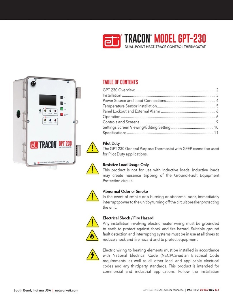
MODEL FPT-130TRACON
®
SINGLE–POINT FREEZE PROTECTION HEAT–TRACE CONTROL
®
®
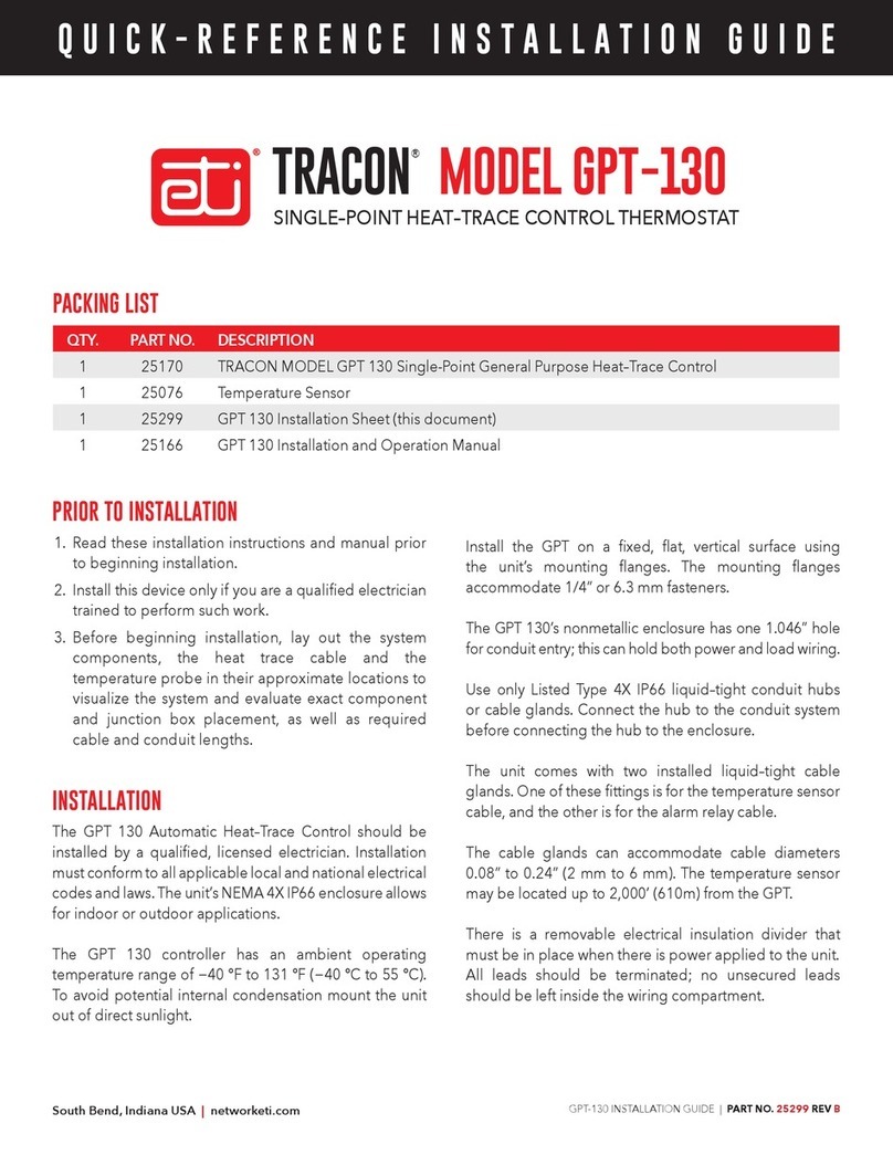
TRACON MODEL GPT-130
SINGLE–POINT HEAT–TRACE CONTROL THERMOSTAT
REPLACEMENT KIT
REPLACEMENT KIT
TRACON MODEL GPT-230
DUAL–POINT HEAT–TRACE CONTROL THERMOSTAT
REPLACEMENT KIT
FPT/GPT PCB REPLACEMENT KIT MANUAL
Ordering & Misc Information................................................................. 9

2
ITEMS INCLUDED
South Bend, Indiana USA | networketi.com FPT/GPT PCB REPLACEMENT MANUAL | PART NO.25594 REV A
PLEASE NOTE:
GPT/FPT printed circuit boards were completely revised in July 2019. When
replacing boards on units purchased prior to July 2019, all boards need to be
replaced. The new ones are not backward compatible with the older boards.

3
South Bend, Indiana USA | networketi.com
25175 PCB ASSY FPT130 CONTROL BOARD
25132 GPT RELAY BOARD
INSTALLATION OF FPT130 BOARD SET
•REMOVE POWER FROM UNIT BEFORE ATTEMPTING TO REPLACE BOARD SET.
•Remove the clear plastic cover and front panel from the FPT130 and set the 1/2
plastite screws to one side for later installation.
•Disconnect the ribbon cable from the old GPT RELAY BOARD.
•Remove the screw holding the grounding strap from the front panel and set aside.
•Remove the remaining four mounting screws (#6, 1/4" plastite screws) and set
aside.
•Remove the old GPT RELAY BOARD and set aside.
•Install the new GPT RELAY BOARD and re-install all mounting screws.
•Re-install the screw holding the grounding strap from the front panel.
FPT/GPT PCB REPLACEMENT MANUAL | PART NO.25594 REV A

4
•Remove old control board by removing the four mounting screws,
power supply connector and disconnecting the ribbon cable from
the GPT RELAY BOARD.
•Install the new control board and install the four mounting screws,
hand tight.
•Re-install the power connector.
•Route the power supply wires to avoid projecting pins (circled in
red) and secure in place with Kapton tape.
•Re-install the ribbon cable going to the new GPT RELAY BOARD.
•Re-install the front panel using the 3/8 inch plastite screws.
•Re-install the plastic cover using the 1/2 inch plastite screws.
FPT/GPT PCB REPLACEMENT MANUAL | PART NO.25594 REV A
South Bend, Indiana USA | networketi.com

5
South Bend, Indiana USA | networketi.com
INSTALLATION OF GPT130 BOARD SET
25132 GPT RELAY BOARD
•REMOVE POWER FROM UNIT BEFORE ATTEMPTING TO REPLACE BOARD SET.
•Remove the clear plastic cover and front panel from the GPT130 and set the 1/2
plastite screws to one side for later installation.
•Disconnect the ribbon cable from the GPT RELAY BOARD
•Remove the screw holding the grounding strap from the front panel and set
aside.
•Remove the remaining four mounting screws (#6, 1/4" plastite screws) and set
aside.
•Remove the old GPT RELAY BOARD and set aside.
•Install the new GPT RELAY BOARD and re-install all mounting screws.
•Re-install the screw holding the grounding strap from the front panel.
25130 PCB ASSY GPT130 CONTROL BOARD
FPT/GPT PCB REPLACEMENT MANUAL | PART NO.25594 REV A

6
JP1
JP2
FPT130
Thermistor
Fault FPT130
Set
Point
GPT
Heat On
Fire Prot Lock
Heat Off
1
01
1
0
0
1
0
0
1
50F
45F
30F
38F
South Bend, Indiana USA | networketi.com
•Remove old control board by removing the four mounting screws,
power supply connector and disconnecting the ribbon cable from
the GPT RELAY BOARD.
•Install the new control board and install the four mounting screws
hand tight.
•Re-install the power connector.
•Route the power supply wires to avoid projecting pins (circled in
red) and secure in place with Kapton tape.
•Re-install the ribbon cable going to the GPT RELAY BOARD.
•Re-install the front panel using the 3/8 inch plastite screws.
•Re-install the plastic cover using the 1/2 inch plastite screws.
FPT/GPT PCB REPLACEMENT MANUAL | PART NO.25594 REV A

7
South Bend, Indiana USA | networketi.com
INSTALLATION OF GPT230 BOARD SET
•REMOVE POWER FROM UNIT BEFORE ATTEMPTING TO REPLACE BOARD SET.
•Open the GPT230 clear cover and remove the front panel by removing the six
plastite screws and set them to one side for later installation.
•Disconnect the two ribbon cables from the old GPT RELAY BOARDS in the
bottom of the housing.
•Remove the screw holding the grounding strap from the old front panel and
set it aside.
•Remove power connector from the lower front panel board.
•Set aside the old front panel to be returned to ETI or disposal.
•Remove the old GPT RELAY BOARDS by removing the screws circled in red
(picture next page) and set the screws aside for later use.
•Remove and set aside the old boards to be returned to ETI or disposal.
•Install the new GPT RELAY BOARDS and re-install all mounting screws hand
tight.
•Re-install the screw holding the grounding strap to the front panel.
•Re-connect the two ribbon cables to the GPT RELAY BOARDS
•Re-connect the power connector to the lower front panel board.
•Install the new front panel and close the clear cover.
25422 TOP PANEL ASSEMBLY, GPT230
FPT/GPT PCB REPLACEMENT MANUAL | PART NO.25594 REV A

8
South Bend, Indiana USA | networketi.com
25132 GPT RELAY BOARDS
FPT/GPT PCB REPLACEMENT MANUAL | PART NO.25594 REV A

9
ORDERING INFORMATION
Part Number Description
25591 FPT 130 PCB REPLACEMENT KIT
25594
1850 North Sheridan Street
South Bend, IN 46628
FPT/GPT PCB REPLACEMENT MANUAL | PART NO.25594 REV A
RETURNS AND REPLACEMENT PART PURCHASES
Equipment cannot be returned for credit once it has
been installed. ETI will repair or replace faulty equip-
ment under warranty. Prior to removal of equipment for
warranty return, please contact ETI Technical Support for
troubleshooting assistance.
Before returning a unit to ETI, obtain a Return Merchandise
Authorization from our Customer Service Department,
available between 8:00 a.m. and 5:00 p.m. Eastern Time. If
possible, use the original container and packing materials
when packing the unit for shipment. It is important to
mark the Return Merchandise Authorization clearly
on the outside of the shipping container so that it may
be correctly processed upon receipt at ETI, Inc. For
more information about replacement parts or for a
replacement Data Sheet or Manual, please visit
www.networketi.com.
Copyright © 2019 ETI,
®
All rights reserved.
South Bend, Indiana USA | networketi.com
25592 GPT 130 PCB REPLACEMENT KIT
GPT 230 PCB REPLACEMENT KIT
25593
FTP/GPT PCB REPLACEMENT MANUAL
(This Document)
CONTACTING CUSTOMER SERVICE
For assistance, contact Customer Service. Office hours are
from 8:00 AM until 5:00 PM ET.
Email: info@networketi.com
Web: networketi.com
Mail: ETI
LIMITED WARRANTY
ETI’s two year limited warranty covering defects in
workmanship and materials applies. Contact Customer
Service for complete warranty information.
DISCLAIMER
ETI makes no representations or warranties, either
expressed or implied, with respect to the contents
of this publication or the products that it describes,
and specifically disclaims any implied warranties of
merchantability or fitness for any particular purpose. ETI
reserves the right to revise this publication, and to make
changes and improvements to the products described
in this publication, without the obligation of ETI to notify
any person or organization of such revisions, changes or
improvements.
Other manuals for Tracon FPT-130
3
This manual suits for next models
5
Table of contents
Other ETI Thermostat manuals
Popular Thermostat manuals by other brands
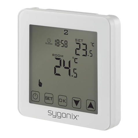
Sygonix
Sygonix Touch 2 operating instructions

Nexans
Nexans MILLITEMP CDFR-003 User's manual & installation instructions
Honeywell
Honeywell T6812DP08 operating manual

Carrier
Carrier 33AW-CS1 user manual
Azbil
Azbil TY6300Z1000 Specifications & instructions
Emerson
Emerson 1F85U-22NP Installation and operating instructions
