2
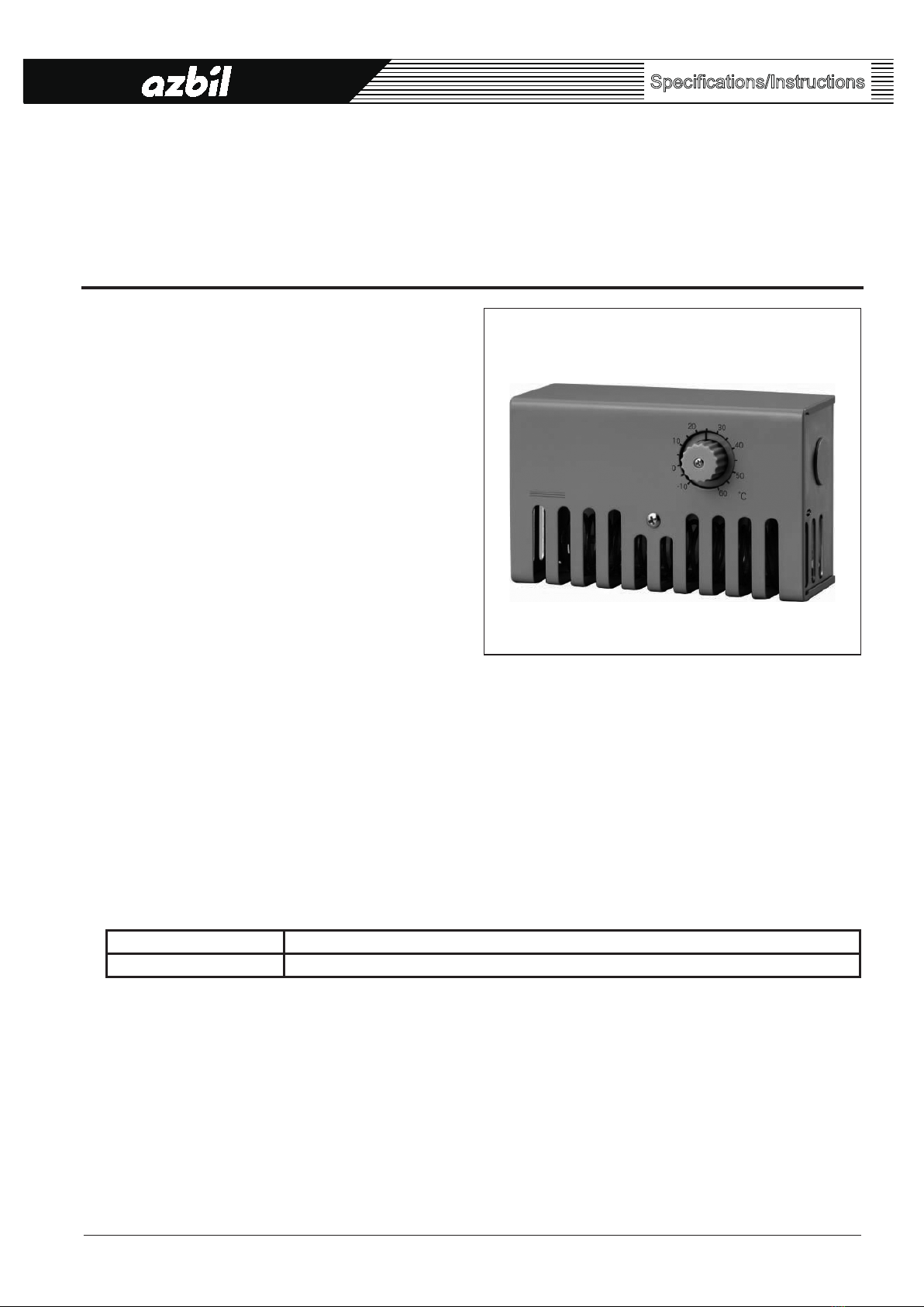
AB-6601
Safety Instructions
Please read instructions carefully and use the product
as specied in this manual.
Be sure to keep this manual near by for ready reference.
Usage Restrictions
This product is targeted for general air conditioning.
Do not use this product in a situation where human
life may be affected.
If this product is used in a clean room or a place
where reliability or control accuracy is particularly
required, please contact our sales representative.
Azbil Corporation will not bear any responsibility for
the results produced by the operators.
zCautions for connecting to system
•If this product breaks down, it does not have function
to avoid or notify the abnormal conditions to other
equipment.
Please take countermeasures independently from this
product.
•If the enclosed liquid leaks, the contacts are welded, etc.,
the output might be stuck to ON.
To use this product for controlling a heating device
such as hot water heater, be sure to implement safety
measures, e.g., preventing dry-heating.
zProhibitions for installing this product
Do not install the product in the following environments.
Doing so might cause malfunction of the device or device
failure in a short period of usage.
•Where special chemicals or corrosive gas (such as
ammonia, sulfur, chlorine, ethylenic compound, acids,
etc.) exist.
•Where water droplets or excessive damp air exists.
•Where condensation is made on the product.
•Where exposed to direct sunlight or high temperature.
•Where exposed to direct wind or rain.
•Where vibrations or shocks are applied.
zCautions for installing this product
•Install this product in a location where representative
temperature of the measuring object can be measured.
•Do not install the product in locations such as the
following.Temperature may not be correctly measured.
•Where exposed to warm or cold wind directly.
•Where air stagnates or there is a draft.
• Where the product cannot be securely mounted.
• Where unauthorized persons can have easy access.
•Secure space around the product for maintenance.
Warnings and Cautions
WARNING
Alerts users that improper
handling may cause death or
serious injury.
CAUTION
Alerts users that improper
handling may cause minor injury
or material loss.
Signs
Alerts users possible hazardous conditions
caused by erroneous operation or erroneous
use. The symbol inside indicates the
specic type of danger.(For example, the sign
on the left warns of the risk of electric shock.)
Notifies users that specific actions are
prohibited to prevent possible danger. The
symbol inside graphically indicates the
prohibited action.(For example, the sign on
the left noties that disassembly is prohibited.)
Instructs users to carry out a specific
obligatory action to prevent possible danger.
The symbol inside graphically indicates
the actual action to be carried out. (For
example, the sign on the left indicates general
instructions.)
WARNING
If this product is connected to a system, be
sure to implement safety measures.
Failure to do might cause re.
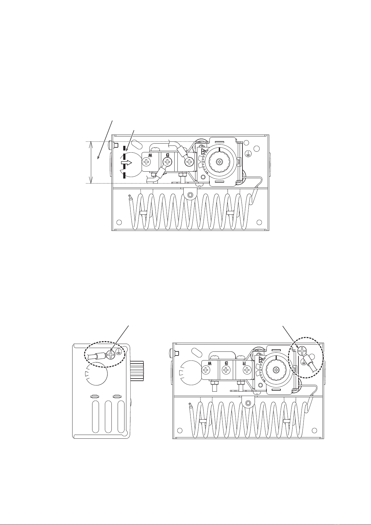
Be sure to ground the product with ground
resistance of less than 100 Ω.
Improper grounding might cause electric
shock or malfunction.
Before wiring or servicing, be sure to turn off
the power to this product.
Failure to do might cause electric shock or
device failure.
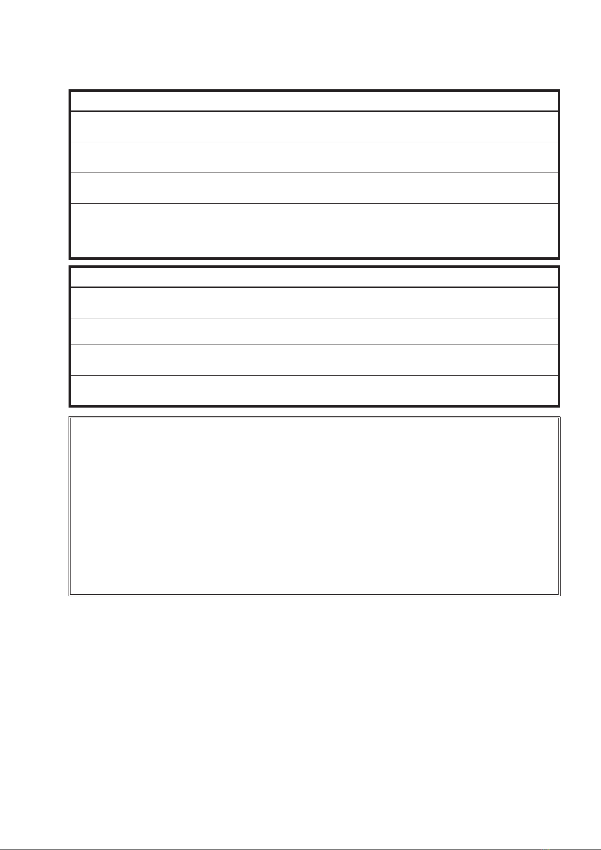
Before attaching or detaching the terminal
cover for wiring, be sure to turn off the power
to the product and all the connected devices.
After the wiring work, attach the terminal
cover at the original position.
Failure to do so might cause electric shock.
If seal connectors or conduits cannot be used,
use grommets.
Failure to do so might cause electric shock
due to touching the terminals.