ETI TER-9 User manual
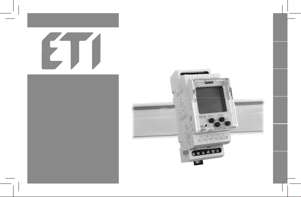
TER-9
Multifunction digital
thermostat
E
N
E
N
P
L
R
U
S
L
O
C
R
O
H
U

- 2 -
Contents
3
4
5
6
8
9
10
11
12
14
18
20
24
26
27
28
29
Alert ................................................................................................................
Characteristics ...............................................................................................
Technical parameters ....................................................................................
Device description .........................................................................................
Symbol, Connection, Temperature sensor TC, TZ .......................................
Mode precedence, Language settings .........................................................
Menu overview ..............................................................................................
Control description .......................................................................................
TER display and settings ..............................................................................
Thermostat functions ...................................................................................
Time and date setting ...................................................................................
Time program ................................................................................................
Setting the switching modes ........................................................................
Setting options ..............................................................................................
Reset ...............................................................................................................
An example of programming .......................................................................
Replacing the battery ...................................................................................

- 3 -
E
N
Warning
Device is constructed for connection in
1-phase main alternating current voltage AC
230V or 24V AC/DC (based on type of device)
and must be installed according to norms valid
in the state of application. Connection according to the
details in this direction. Installation, connection, setting
and servicing should be installed by qualied electrician
sta only, who has learnt these instruction and functions
of the device. This device contains protection against
overvoltagepeaksanddisturbanciesin supply.For correct
function of the protection of this device there must be
suitable protections of higher degree (A,B,C) installed
in front of them. According to standards elimination of
disturbancies must be ensured. Before installation the
main switch must be in position “OFF” and the device
should be de-energized. Don´t install the device to
sources of excessive electro-magnetic interference.
By correct installation ensure ideal air circulation so
in case of permanent operation and higher ambient
temperature the maximal operating temperature of the
device is not exceeded. For installation and setting use
screw-driver cca 2 mm. The device is fully-electronic -
installation should be carried out according to this fact.
Non-problematic function depends also on the way of
transportation, storing and handling. In case of any signs
of destruction, deformation, non-function or missing
part, don´t install and claim at your seller it is possible to
dismount the device after its lifetime, recycle, or store in
protective dump.

- 4-
Characteristics
- digital thermostat with 6 functions and built-in time switch clock with
day, week and year program.You can also limit temperature functions
and courses this way in real time.
- the temperature prole can be changed using the time program
- complex home and water heating, solar heating, etc.
- two thermostats in one, two temperature inputs, two outputs with dry
contact
- maximum universal and variable thermostat including all ordinary
thermostat functions
- functions: two independent thermostats, dependent thermostat,
dierential thermostat, two level thermostat, zone-based thermostat,
dead zone thermostat
- monitoring function for short circuit or sensor disconnection
- program setting of output functions, calibration of sensors according
to reference temperature (oset)
- the thermostat is subject to the digital clock programs
- wide range for setting control temperature - 40 to 110°C
- clear display of set and measured data on a backlit LCD
- Switching modes:
- Auto – automatic switching mode:
- Programme
– switching based on a programme (astro or time).
- Random
– switches randomly in a 10–120 minute interval.
- Holiday
– holiday mode – option of setting up a period for
which the timer will be blocked, i.e. will not switch based on the
set programmes.
- Manual
– manual mode – option of controlling the individual
output relays manually
- Options of the automatic switching programme:
- ter - switches according to set thermostat function
(switches based on temperature sensors and associated
function)
- time program - switches or sets required temperature according
to set time program
- 100 memory locations for time programs (common for both
channels).
- Programming can be performed under voltage and in backup mode.
- The relay outputs do not work in backup mode (battery-powered)
- Choice of menu display - CZ / SK / EN / RO / PL / HU / RU (factory
setting EN).
- Choice of automatic daylight savings time transition according to
time zone.
- Backlit LCD display.
- Easy and quick setting with the help of 4 control buttons.
- Pluggable transparent cover on front panel.
- The time switch clock has a battery backup, which retains data in
case of a power outage (reserve backup time - up to 3 years).
- Power supply: AC 230V or 24V AC/DC (based on type of device).
- 2-module, DIN rail mounted

- 5 -
E
N
Technical parameters
Supply
Supply terminals:
Supply voltage:
Consumption:
Supply voltage tolerance:
Backup battery type:
Measuring circuit
Measuring terminals:
Temperature range:
Hysteresis (sensitivity):
Diference:
Sensor:
Sensor failure indication:
Accuracy
Measuring accuracy:
Repeat accuracy:
Temperature dependance:
Number of function:
Output
Number of contacts:
Rated current:
Switching capacity:
Switching voltage:
Output indication:
Mechanical life:
Electrical life (AC1):
A1 - A2
AC230 V (AC50-60Hz), galvanically
isolated or AC/DC 24 V, not galvani-
cally isolated
max. 4 VA
-15 %; +10 %
CR 2032 (3V)
T1-T1 a T2-T2
-40.. +110 °C
adjustable within range 0.5...5 °C
adjustable 1 .. 50 °C
thermistor NTC 12 kΩ at 25 °C
displayed on LCD *
5 %
< 0.5 °C
< 0.1 % / °C
6
1x switching for each output (AgNi)
8 A / AC1
2000 VA / AC1, 240 W / DC
250 V AC1 / 30 V DC
symbol ON/OFF
1x10
7
1x10
5
up to 3 years
max. ±1s/ day at 23°C
1 min.
min. 10 years
100
daily , weakly, yearly
LCD display, with back light
-10.. +55 °C
-30.. +70 °C
4 kV (supply - output)
any
DIN rail EN 60715
IP 40
from front panel
/ IP 20 clips
III.
2
max.1x 2.5, max.2x1.5/ with sleeve
max. 1x2.5
90 x 35.6 x 64 mm
(230V) 127 g (24V) 120 g
EN 61812-1. EN 61010-1. EN 60730-2-9;
EN 60730-1; EN 60730-2-7
Time circuit
Real time back-up:
Accuracy:
Minimum interval:
Data stored for:
Program circuit
Number of memory places:
Program(SHT-3, SHT-3/2):
Data readout:
Other information
Operating temperature:
Storage temperature:
Electrical strength:
Operating position:
Mounting:
Protection degree:
Overvoltage cathegory:
Pollution degree:
Max. cable size (mm2):
Dimensions:
Weight:
Standards:
* ERROR - sensor short circuit
NO SENSOR - interruption sensor
- 6 -
TER-9
15 16 18 25 26 28
A1 A2 T1 T1 T2 T2
PRG +
MAN
_
MAN 2
ESC
OK
RESET
Auto
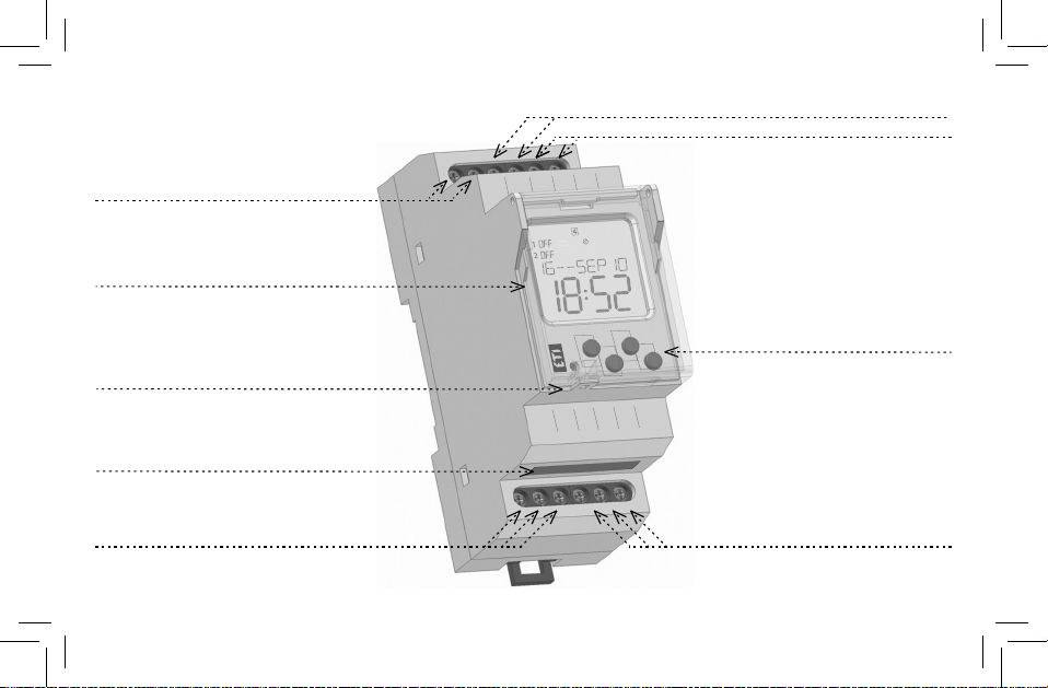
Supply voltage terminal (A1)(A2)
Display with back-light
Place for seal
Control buttons
Output - channel 2 (25-26-28)
Output - channel 1 (15-16-18)
Description Terminals -sensor 1
Terminals -sensor 2
Plug-in module for replacing backup battery
- 7 -
TER-9
ManProgAuto + t
E
N
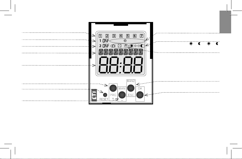
Indicates the day in the week
Indication (1st channel)
Indication (2nd channel)
Display of data / settings menu / or dis-
play of current measured temperature
Control button PRG / +
Control button MAN1 / -
Control button OK
Switches display date/measured
temperature of channel 1, 2
Control button MAN2 / ESC
Reset
CONTROL OF A DISPLAY WITH BACKLIGHT
Power on: Display is illuminated with a backlight for 10 seconds from the last button press. The display continuously
shows the settings – date, time, day of the week, contact state and programme. Permanent on / o is activated by
simultaneous presses of the MAN, ESC, OK buttons. After activating the permanent on/o, the display will ash briey.
Backup mode: After 2 minutes, the display switches to the sleep mode, i.e. shows no information. The display can be
activated by pressing any button.
Time display
Operating modes indication
12/24 hours format /
AM <− ; PM −>
Indication of the switch
program
- 8 -
Un
15 16 18 25 26 28
A1 A2 T1 T1 T2 T2
Sensor 1 Sensor 2
15 25
16
A2
A1
°C
T1
T1
T2
T2
18 26 28
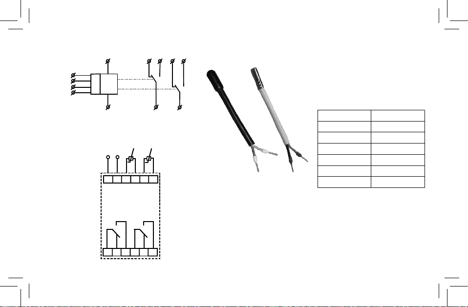
Connection
Symbol Temperature sensor TC, TZ
14.7
9.8
6.6
4.6
3.2
2.3
TC TZ
Temperature (°C) NTC sensor (kΩ)
Tolerance of sensor NTC 12 kΩis ± 5% at 25 °C..
Resistance value of sensors based
on temperature
20
30
40
50
60
70
- 9 -
ProgAuto
PRG OK
+_OK
+_
ESC
Prog
Prog
Prog
Prog
Prog
Prog
Prog
Prog
Prog Prog
OK
ter options language
E
N
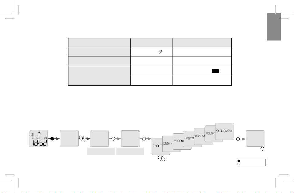
Mode precendence
mode precedence
display output mode
ON / OFF
manual control
ON / OFF holiday mode
ON / OFF time program Prog
ter thermostat
mode with the highest
priority
Language settings
ter and Time Program can work at the same time on a single channel.
Language selection
language
options
-
long press
(>1s)
- short press (<1s)

- 10 -
Auto Prog Prog Prog
Menu overview
setting the display of
the time format
setting the display of
the date format
setting the display of
the week day
setting the switch
from the summer to
the winter time
setting the date
setting the current
time add a program
edit the program
delete a program
setting and adjusting
the time program
time
date
su-wi
week day
date form
time form
add
edit
delete
setting the time
and date
time/date time prog
selection of thermo-
stat functions
temperature settings
hysterezis setting
temperature dieren-
ce settings
delay settings
upon switching
on/o
measured temperatu-
re change
setting temperature
units
thermostat settings
function
temperatur
hysteresi
differenc
delay
offset
units
ter

- 11 -
Prog Prog Prog
E
N
PRG - entrance into
programming menu
+_
- browsing in menu
- setting of values
+_
- quick shifting
during setting of
values
OK
- entrance into
required menu
- conrmation
- switch. between display
ESC
- one level up
- a step back
ESC
- back to the starting
menu
Control
Device diers short and long button press. In the manual marked as:
- short button press (<1s)
- long button press (>1s)
After 30s of inactivity (from the last press of any button) will device
automatically returns into starting menu.
In the start screen, press OK to toggle between displaying the date or
measured temperature.
manual mode
setting the holiday
mode
setting the auto
switching mode setting the language
operating hours for
individual channels
setting time correcti-
on by ± 12.7 s / day
switch modes device options
holiday
manual
language
operating ho
time correct
AUTO
modes options end

- 12 -
Prog
Prog
Prog
Prog
Prog
+_
+_
+_+_
+_
Prog
Prog
Prog
Prog
Prog
Auto
PRG OK OK
OK OK
OK OK
OK
OK
+_
+_
+_
ESC
ESC
ESC
Prog
Prog Prog
OK
TER Zobrazení a nastavení TER
selection of thermo-
stat functions
temperature settings
hysterezis setting
channel choice temperature
settings
channel choice hysteresis setting in
range of 0.5 - 5 °C (F)
function selection
TER
function function
temperatur temperatur
hysteresi hysteresi
°C
°C
channel
channel
set
channel
channel
- If the function
TER
is active, then
symbol„Auto“ is displayed on the
screen
- If the entered switching delay is
shown on the display„Auto + t“

- 13 -
Prog Prog
Prog
Prog
Prog Prog
Prog
Prog
Prog
Prog
OK OK
OK
+_
+_
+_
+_
+_+_
+_
+_
Prog
Prog
OK OK OK
ESC
ESC
ESC
OK
OK
+_
Prog
Prog
on
OK OK
OK
+_
Prog
Prog
on
E
N
-
long press
(>1s)
- short press (<1s)
channel choice oset setting in a
range of ±20
channel choice
temperature dieren-
ce settings
delay settings
upon switching
on/o
measured temperatu-
re change
°C
°C
differenc differenc
channel
channel
channel
channel
delay delay
offset offset
ON - switching on,
OFF - switching o
dierence setting in a
range of 1-50 °C (F)
delay setting 0-60
seconds
- 14 -
Prog
Prog Prog
Prog
Prog
+_
+_
ESC
ESC
OK OK
T1
Ts1
dy1 dy2 dy1 dy2
15-18
H1
H1
25-28
T2
Ts2
dy1 dy2 dy1 dy2
H2
H2
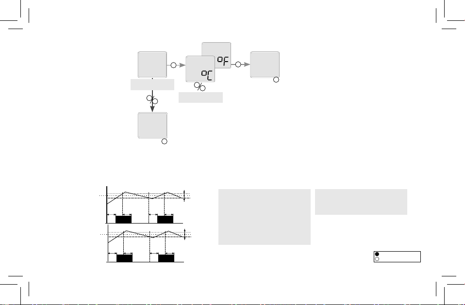
selection of unit
Legend:
Ts1 - real (measured) temperature 1
Ts2 - real (measured) temperature 2
T1 - adjusted temperature T1
T2 - adjusted temperature T2
H1 - adjusted hysteresis for T1
H2 - adjusted hysteresis for T2
dy1 - set switching delay of the output
dy2 - set delay on output breaking
15-18 output contact (for T1)
25-28 output contact (for T2)
- Output contact switched until adjusted
temperature is reached. Hysteresis elimi-
nates frequent switching. Heating/cooling
function adjusted in the menu.
setting temperature
units
set
set
units units
end
2 independent single-stage thermostat
Heater function
Heater function
Thermostat functions
-
long press
(>1s)
- short press (<1s)

- 15 -
H2
T1
H1
T2 Ts2
Ts1
15-18
15-18
25-28
dy1 dy2 dy1 dy2
dy1 dy2 dy1 dy2 dy1
dy1 dy2 dy1 dy2
H2
H2
H1
H1
25-28
15-18
Ts1
Ts2
D
D-H1
D
D-H2 D
dy1
dy1 dy2
dy1
dy2
E
N
Legend:
Ts1 - real (measured) temperature 1
Ts2 - real (measured) temperature 2
T1 - adjusted temperature T1
T2 - adjusted temperature T2
H1 - adjusted hysteresis for T1
H2 - adjusted hysteresis for T2
dy1- set switching delay of the output
dy2 - set delay on output breaking
25-28 output contact (for T2)
15-18 output contact (intersection T1
and T2)
Legend:
Ts1 - real (measured) temperature T1
Ts2 - real (measured) temperature T2
D - adjusted di erence
dy1- set switching delay of the output
dy2 - set delay on output breaking
15-18 output contact (for T1)
25-28 output contact (for T2)
- Output 15-18 is closed, if temperature of both
thermostats is bellow an adjusted level. When any
thermostat reaches adjusted level, the contact 15-18
open. Serial inner connection of thermostats (logic
function AND).
- Switching of output corresponds with input, which
has lower temperature when di ference is exceeded
di erencial thermostat is used for keeping two
identical temperature e.g. in heating systems (boiler
and reservoir), solar systems ( collector, reservoir,
exchanger), water heating ( water heater, water
distribution)etc.
Dependent functions of 2 thermostats
Di erential thermostat

- 16 -
T
15-18
25-28
T1
Ts
H1
H2
D
dy2
dy1
dy1dy2
dy1 dy2 dy1 dy2
dy1
H1
H1
H2
H2
15-18
25-28
T1
T2
Ts
dy1 dy2
H1
H2
D
dy1 dy2
dy1 dy2
dy1 dy2 dy1 dy2
dy1 dy2
H2
H2
H1
H1
T
2-stage thermostat
Thermostat with“WINDOW”
Legend:
Ts - real (measured) temperature T1
D - adjusted di erence
T1 - adjusted temperature T1
T=T1-D
H1 - adjusted hysteresis for T1
H2 - adjusted hysteresis for T2
dy1- set switching delay of the output
dy2 - set delay on output breaking
15-18 output contact
25-28 output contact
Legend:
Ts - real (measured) temperature
T1 - adjusted temperature
T=T1-D
H1 - adjusted hysteresis for T1
H2 - adjusted hysteresis for T2
dy1- set switching delay of the output
dy2 - set delay on output breaking
15-18 output contact
25-28 output contact
- Typical example of use for two-stage thermostat
is e.g in boiler-room, where there are two biolers
from which one is main and the other one is auxi-
liary. The main boiler is managed according to set
temperature and auxiliary boiler is switched in case
temperature falls
under set di erence. Thus it helps to the main
boiler in case outside temperature dramatically
falls. In the range of set di erence (D) output 15-18
functions as normal thermostat to input 1 ( type
1). In case temperature falls under set di erence,
output 2 switches.
- Output is closed (heating) only if temperature is
within adjusted range.If temperature is out of range,
the contact opens. T is set asT1-D.The function is
used for protection of gutters against freezing.
- 17 -
T1
Ts
15-18
25-28
T2
D
H1
H2
dy1 dy2 dy1
dy1 dy2
T
H2
H2
H1
H1
E
N
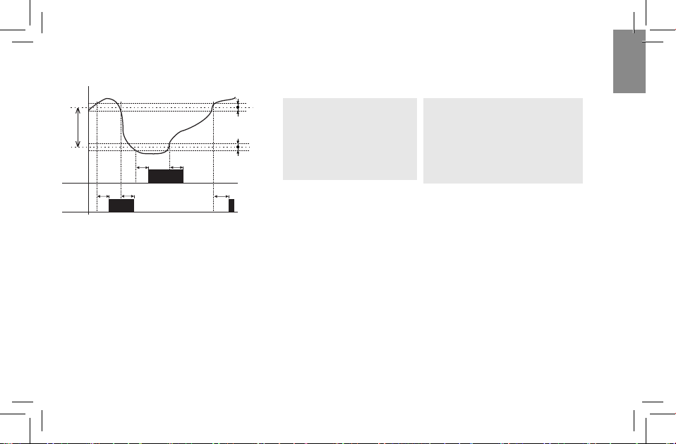
Legend:
Ts - real (measured) temperature
T1 - adjusted temperature
T=T1-D
H1 - adjusted hysteresis for T1
H2 - adjusted hysteresis for T2
dy1- set switching delay of the output
dy2 - set delay on output breaking
15-18 output contact (heating)
25-28 output contact (cooling)
- In case of thermostat with a„dead zone“ , it is
possible to set temperature T1 and a di erence
(respectively a width of dead zone D). If temperature
is higher than T1, output contact of cooling switches
ON; if the temperature gets bellow T1, the contact
switches OFF. If
the temperature gets bellow temperature T, the
contact of heating switches ON and it switches OFF
when temperature T is exceeded. This function can
be used for example for automatic air warming and
cooling in ventilation so the sit is always within the
range T1 and T.
Thermostat with dead zone
- 18 -
ProgAuto
PRG OK OK
OK
OK
+_
+_
+_
+_
Prog
+_
Prog
ProgProg Prog
OKOK
+_+_+_
Prog Prog
OK
+_
Prog
OK
ESC
Prog Prog
OK
ESC
Prog Prog
ESC
Prog
Prog
Prog
Prog
OK
+_
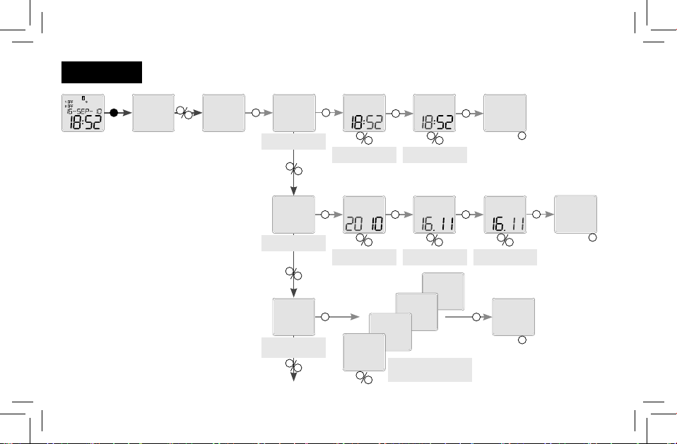
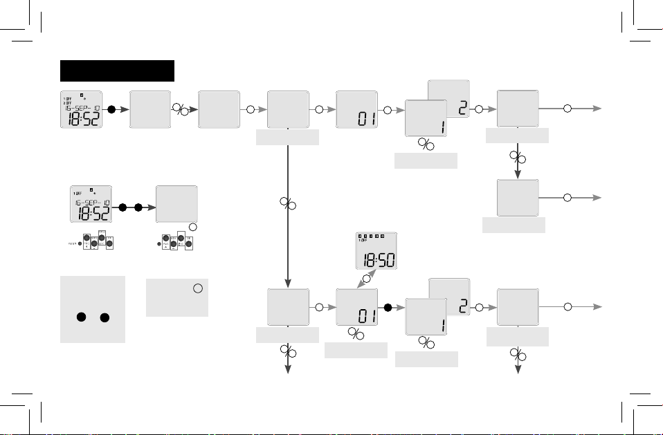
Date and time setting
setting the hours
setting the time
setting the date
setting the switch
between the sum-
mer /winter time
setting the monthsetting the year setting the day
setting the minutes
setting the switch between
the summer and winter
time depending on area
ter time/date time hour minute time
date year month day date
su-wi
su-wi eur
su-wi usa
su-wi rus
no su-wi
su-wi
time/date

- 19 -
+_
+_
+_
Prog
OK
OK
+_
+_
+_
ESC
Prog
Prog
Prog
Prog
Prog
Prog
Prog
Prog
OK
Prog
ESC
Prog
Prog
Prog
Prog
Prog
Prog
Prog
OK
+_
OK
Prog
Prog
OK
ESC
ESC
E
N
setting the week
day
date format
time format
week day
date form
16 sep 10
16/sep/10
16--sep--10
week day
date form
time form
time form 12h
24h
end
-
long press
(>1s)
- short press (<1s)
- After entering the date is normally calculated
and numbered by day of the week : Monday =
rst day of the week
- Numeral showing the day of the week,
may not correspond to the calendar day of
the week. It can be set in the menu„Display
settings of the week .“ Set the number from
the set to the current date
Note: After the date is changed , the
numbering of days back to the standard
numbering ie Monday = rst day of the week
- 20 -
Prog
Prog
ProgAuto
PRG OK OK
+_
+_OK
Prog ProgProg
+_
OK
Prog
Prog
OK
OK
+_
Prog
Prog
Prog
OK
Prog
+_
OK
Prog
OK
+_
OK
+_
+_
OK
ProgAuto
OK
PRG
OK
+
add a program
channel choice
Time program
adjusting the
channel
program choice *
daily program
yearly program
adjusting the daily
program
edit program
ter time prog add prog
channel
channel
day prog
year prog
edit prog
channel
channel
day prog
time program
- press button OK
to complete the
deleting of all set
programs
- in starting menu
(time is shown on
display) - press si-
multaneously button
PRG and OK
and display announ-
ces a notice all
Deleting of all programs
all
Table of contents
Languages:
Other ETI Thermostat manuals


Popular Thermostat manuals by other brands

Daikin
Daikin TSTATD1100-2 Owner's manual and installation instructions

Brivis
Brivis TH4110 quick start guide

Honeywell
Honeywell TB7100A1000 - MultiPro Commercial Thermostat owner's guide

Lutron Electronics
Lutron Electronics LR-HVAC-230-S Setup guide

Pro
Pro T721 Operation manual

Robertshaw
Robertshaw RS4110 user manual


