Eton America Beamer R4 150CC User manual

ETON America
Beamer R4 150cc
Service Manual
Covers:
Beamer R4 PN2F
www.Get2itParts.com
www.Get2itParts.com
www.Get2itParts.com

CONTENTS
1. INFORMATION .............................................................................................................. 4
1.1 SAFETY........................................................................................................................ 4
1.2 NOTES.......................................................................................................................... 4
1.3 SERIAL NUMBER ........................................................................................................ 5
1.4 TORQUE VALUES....................................................................................................... 6
2. MAINTENANCE ............................................................................................................. 8
2.1 MAINTENANCE DATA SPECIFICATIONS ................................................................. 8
2.2 MAINTENANCE SCHEDULE....................................................................................... 8
2.3 FUEL TUBE.................................................................................................................. 9
2.4 THROTTLE OPERATION ............................................................................................ 9
2.5 THROTTLE CABLE ADJUSTMENT ............................................................................ 9
2.6 AIR CLEANER............................................................................................................ 10
2.7 SPARK PLUG............................................................................................................. 10
2.8 IDLE SPEED............................................................................................................... 10
2.9 BRAKE SYSTEM........................................................................................................ 10
2.10 WHEELS AND TIRES .............................................................................................. 11
2.11 GEAR OIL................................................................................................................. 11
2.12 ENGINE STOP SWITCH.......................................................................................... 12
2.13 UPPER – LOWER BEAM CONTROLLER............................................................... 12
3. ENGINE REMOVAL AND INSTALLATION ................................................................ 13
3.1 ENGINE REMOVAL................................................................................................... 13
3.2 ENGINE INSTALLATION........................................................................................... 16
4. CYLINDER HEAD AND VALVES................................................................................ 17
4.1 SERVICE INFORMATION GENERAL....................................................................... 17
4.2 TROUBLE SHOOTING .............................................................................................. 18
4.3 CAMSHAFT COMPOSITION REMOVAL.................................................................. 18
4.4 CYLINDER HEAD REMOVAL.................................................................................... 21
5. LUBRICATION ............................................................................................................. 27
5.1 SERVICE INFORMATION GENERAL....................................................................... 27
5.2 TROUBLESHOOTING ............................................................................................... 28
5.3 ENGINE OIL LEVEL................................................................................................... 28
5.4 ENGINE OIL & FILTER CHANGE.............................................................................. 28
5.5 OIL PUMP REMOVAL................................................................................................ 29
6. CYLINDER / PISTON ................................................................................................ 35
6.1 SERVICE INFORMATION GENERAL....................................................................... 35
6.2 TROUBLESHOOTING ............................................................................................... 35
6.3 CYLINDER REMOVAL............................................................................................... 36
6.4 PISTON REMOVAL.................................................................................................... 37
6.5 PISTON INSTALLTION PISTON RING INSTALLATION .......................................... 40
6.6 CYLINDER INSTALLATION....................................................................................... 41
7. TRANSMISSION / KICK STARTER ...................................................................... 43
7.1 SERVICE INFORMATION.......................................................................................... 43
7.2 TROUBLE SHOOTING .............................................................................................. 43
7.3 CVT DISASSEMBLY L............................................................................................... 43
7.4 KICK STARTER DISASSEMBLY............................................................................... 48
7.5 KICK STARTER ASSEMBLY..................................................................................... 50
7.6 C.V.T ASSEMBLY ...................................................................................................... 50
7.7 ELECTRIC SELF-STARTER MECHANISM.............................................................. 53
7.8 KICK STARTER.......................................................................................................... 53
7.9 REMOVAL OF CVT SYSTEM.................................................................................... 54
7.10 DISASSEMBLY AND INSPECTION OF THE CVT SYSTEM ................................. 54
8. FRONT WHEEL, BRAKES, AND STEERING SYSTEM .................................. 55
8.1 TROUBLESHOOTING........................................................................................... 55
8.2 MAINTENANCE DATA.......................................................................................... 55
8.3 REPLACE SPEEDOMETER CABLE......................................................................... 56
9. REAR WHEEL AND BRAKE SYSTEM................................................................ 60
9.1 TROUBLESHOOTING ............................................................................................... 60
9.2 MAINTENANCE DATA............................................................................................... 60
9.3 REAR WHEEL REMOVAL......................................................................................... 61
9.4 INSPECTING THE REAR WHEEL............................................................................ 62
9.5 REAR BRAKE............................................................................................................. 62
www.Get2itParts.com
www.Get2itParts.com
www.Get2itParts.com

9.6 REAR SHOCK ABSORBER DRAWING.................................................................... 64
10. PLASTIC PARTS..................................................................................................... 65
10.1 FRONT FENDER...................................................................................................... 65
10.2 BODY COVER.......................................................................................................... 65
10.3 CANISTER COMP REMOVAL AND INSTALLATION............................................. 69
11. ELECTRICAL SYSTEM.......................................................................................... 70
11.1 TROUBLESHOOTING............................................................................................. 70
11.2 IGNITION COIL......................................................................................................... 71
11.3 BATTERY INSPECTION........................................................................................... 71
11.4 CHARGING .............................................................................................................. 72
11.5 STARTER MOTOR .................................................................................................. 72
11.6 WIRING DIAGRAM................................................................................................... 73
www.Get2itParts.com
www.Get2itParts.com
www.Get2itParts.com

1. INFORMATION
1.1 SAFETY
●Gasoline is extremely flammable and is explosive under certain conditions. Do not
smoke or allow sparks or flames in your work area.
●Never run the engine in a closed area. The exhaust contains poisonous carbon monoxide
gas that may cause loss of consciousness and lead to death.
●The battery electrolyte contains sulfuric acid. Protect your eyes, skin and clothing. If
contact is made with skin, flush thoroughly with water and call a doctor if electrolyte gets
in your eyes.
1.2 NOTES
All information, illustrations, directions and specifications included in this publication are
base on the latest product information available at the time of approval for printing.
E-TON POWER TECH CO., LTD. reserves the right to make changes at any time without
notice and without incurring any obligation whatever.
No part of this publication may be reproduced without written permission.
www.Get2itParts.com
www.Get2itParts.com
www.Get2itParts.com
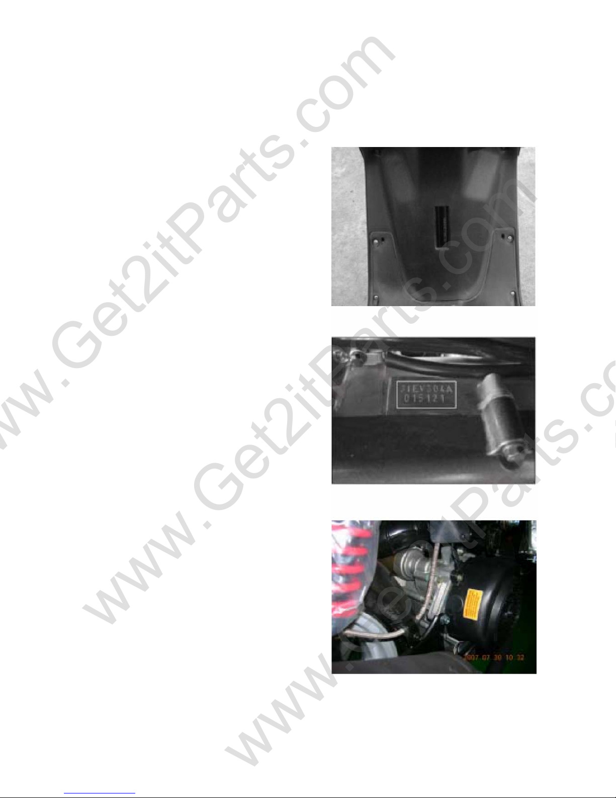
1.3 SERIAL NUMBER
The frame serial number is stamped on the front of the frame, just at the front of footrest plate. The engine
serial number is stamped on the left side of the engine crankcase.
Frame serial number
Engine serial
number(2007)
Engine serial
number(2008)
www.Get2itParts.com
www.Get2itParts.com
www.Get2itParts.com
1.4 TORQUE VALUES
FRAME
Part to tightened Thread
size
Tightening torque Remarks
N-m kg-m ft.lb
Handlebar upper holder bolt M10 30-40 3.0-4.0 22.1-29.5
Front fork nut upper M25 55-65 5.5-6.5 40.6-47.9
below 14 1.4 10.3
Front axle nut M10 30-40 3.0-4.0 22.1-29.5
Rear axle nut M20 110-130 11.0-13.0 81.1-95.9
Engine hanger bolt
/
Frame
M10 50-60 5.0-6.0 36.9-44.3
/
Engine 30-40 3.0-4.0 22.1-29.5
Front brake calliper bolt M8 24-30 2.4-3.0 17.7-22.1 Loctite 271
Brake oil tube bolt M8 24-30 2.4-3.0 17.7-22.1
Rear brake calliper bolt M8 24-30 2.4-3.0 17.7-22.1 Loctite 271
Brake disk bolt M8 30-40 3.0-4.0 22.1-29.5
Exhaust pipe mounting nut M6 12-15 1.2-1.5 8.9-11.1
Exhaust muffler bolts M8 20-30 2.0-3.0 14.8-22.1
www.Get2itParts.com
www.Get2itParts.com
www.Get2itParts.com
ENGINE
Part to tightened Thread
size
Tightening torque Remarks
N-m kg-m ft.lb
Spark plug M10 10-12 1.0-1.2 7.4-8.9
Cylinder head bolts M6 10-14 1.0-1.4 7.4-10.3
Tappet adjusting nut M5 7-11 0.7-1.1 5.2-8.1
Oil drain bolt M12 20-30 2.0-3.0 14.8-22.1
Clutch outer nut M10 55 5.5 40.6
Drive face nut M12 55 5.5 40.6 Loctite 638
Catalyst 7649
Camshaft holder nuts M8 19-22 1.9-2.2 14.0-1 6.2
Hole cap tap adjusting M30 7-9 0.7-0.9 5.2-6.6
Stud bolt M7 8-12 0.8-1.2 5.9-8.9
Starting clutch outer M22 95-96 9.5-9.6 68-69.4
GENERALITY
General bolt M5 3.5-5.0 0.3-0.5 2.2-3.7
M6 10.0~14.0 1.0-1.4 7.4-10.4
M8 20.0~30.0 2.0-3.0 14.8-22.1
M10 30.0~4.00 3.0-4.0 22.1-29.5
M12 50.0~60.0 5.0-6.0 36.9-44.2
www.Get2itParts.com
www.Get2itParts.com
www.Get2itParts.com

2. MAINTENANCE
2.1 MAINTENANCE DATA
SPECIFICATIONS
SPARK PLUG GAP 0.6-0.7 mm
RECOMMENDED SPARK PLUGS NGK CR7HSA
THROTTLE LEVER FREE PLAY 5-10 mm
IDLE SPEED 1700-1 900 rpm
BRAKE LEVER FREE PLAY 15-25 mm
ENGINE OIL SAE 15W-40
GEAR LUBRICATION OIL SAE 80W-90 gear Oil
2.2 MAINTENANCE SCHEDULE
The maintenance internals in the follow table is based upon average riding, conditions. Riding in unusually
dusty areas, require more frequent servicing.
www.Get2itParts.com
www.Get2itParts.com
www.Get2itParts.com

Maintenance Schedule
Four Stroke Vehicles
WP-0027
Scheduled
Maintenance
300KM Every1000KM Every3000KM Every6000KM Every12000KM
200Miles600Miles2000Miles3700Miles7500Miles
NEW 1Month3Months 6Months 1Year
1Aircleanerelement I*C* R(paper) R(sponge)
2Aircleaner I
3Oilfilter(Screen) C C
4Engineoil Change I Change
5Tire,pressure I I
6Battery I I
7Sparkplug I I R
8Carburetor(idlespeed) I I
9Steeringbearingandhandles I I
10
Checktransmissionforleak‐
age I I
11Checkcrankcaseforleakage I I
12Transmissionoil Change Change
13Drivebelt/roller I R
14Fueltankswitchandlines I I
15
Throttlevalveoperationand
cable I I
16Engineboltsandnuts I I
17
Cylinderhead,cylinder,and
piston I
18
Exhaustsystem/cleaning
carbon I
19CamChain/ignitiontime I I
20Valveclearance I I I I I
21Shockabsorbers I I
22Front/Rearsuspension I I
23Main/Sidestands I I/L
24Crankcase(PCV)Valve I I
25
Brakemechanism/brakelin‐
ing(pad) I I
26
TightenallBolts/Nuts&Fas‐
teners
I I
*=Cleanorreplacetheaircleanerelementmoreoftenwhenthevehicleisoperatedondusty
#=Maintenanceshouldbeperformedmoreoftenifthevehicleisfrequentlyoperatedathigh
speedforprolongedtimeandafterthevehiclehasaccumulated50,000miles.
roadsorinaheavilypollutedenvironment.
Code:
I=Inspection,clean,andadjust
R=Replace
C=Clean(replacedifnecessary)
L=Lubricate
www.Get2itParts.com
www.Get2itParts.com
www.Get2itParts.com

2.3 FUEL TUBE
Inspect the fuel lines for deterioration, damage, or leaking,
and replace if necessary.
2.4 THROTTLE OPERATION
Inspect the hand grip for smooth full opening and
automatic full closing in all steering positions.
Inspect for deterioration, damage, or kinking in the throttle
cable, and replace it if necessary.
Disconnect the throttle cable at the upper end. Lubricate
the cable with commercially available lubricant to
prevent premature wear.
The BEAMER R2-50 uses a manual choke. Check that the
choke opens and closes smoothly. If it does not, check the
wire connecting to the switch.
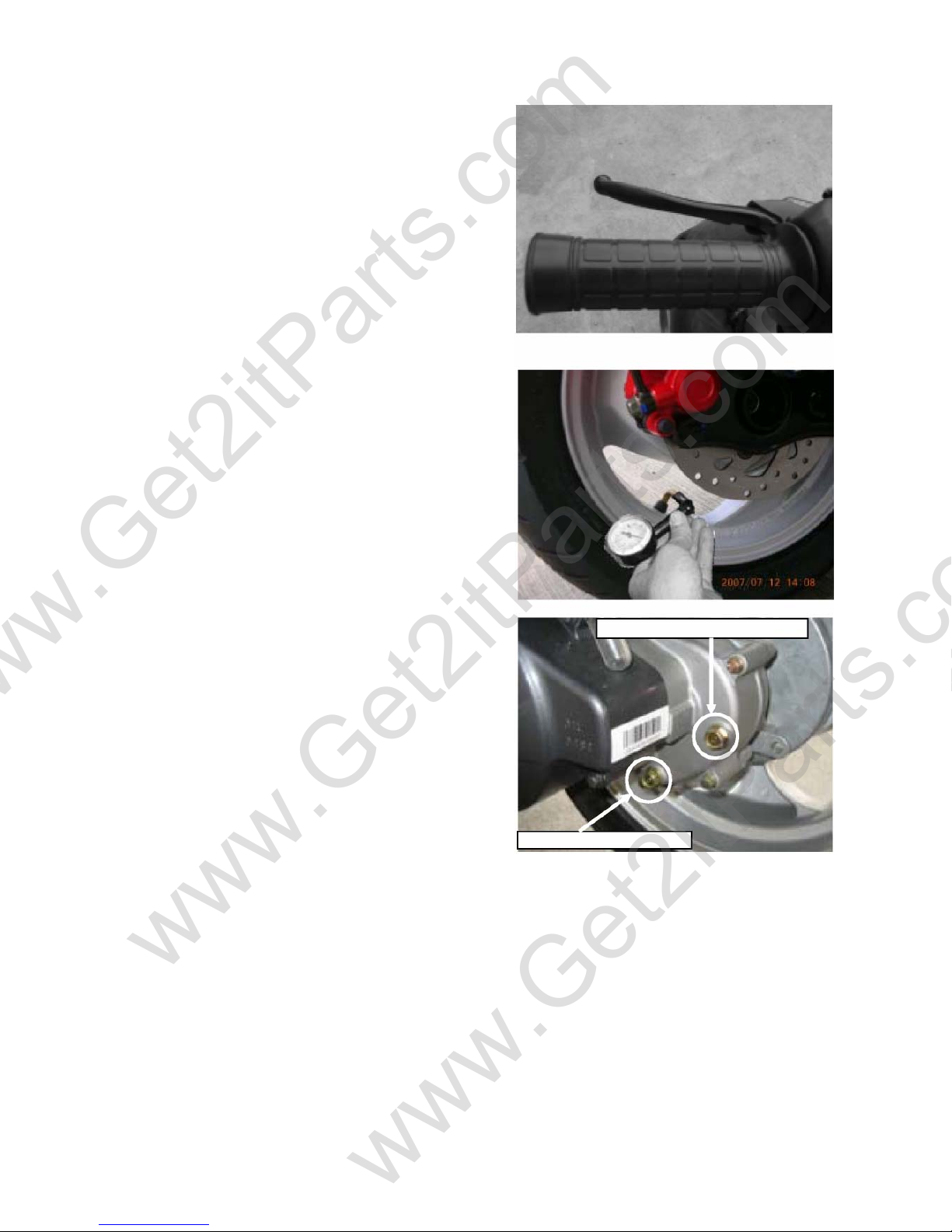
2.5 THROTTLE CABLE ADJUSTMENT
Slide the rubber cap of the adjuster off the throttle
housing, loosen the lock nut, and adjust the free play of
the throttle lever by turning the adjuster on the throttle
housing. Inspect the free play of the throttle lever.
This free play should be 5-10mm.
www.Get2itParts.com
www.Get2itParts.com
www.Get2itParts.com

2.6 AIR CLEANER
Unscrew the air cleaner cover screws.
Pull out the air filter from the air cleaner case.
Wash the component in non-flammable solvent and
squeeze out the solvent thoroughly. Let it dry completely.
Soak the filter in gear oil and then squeeze out the excess
oil.
Install the component into the air cleaner carefully.
2.7 SPARK PLUG
The spark plug is located at the front of the engine.
Disconnect the spark plug cap and unscrew the spark
plug. Check the spark plug electrodes for wear.
Replace the spark plug if the electrodes and insulator tip
appear unusually fouled or burned.
Discard the spark plug if there is apparent wear or if the
insulator is cracked or chipped.
The spark plug gap should be set to 0.6-0.7mm.
With the sealing washer attached, thread the spark plug
in by hand to prevent cross threading.
Tighten the spark plug to 10-12 N-m.
2.8 IDLE SPEED
Connect a tachometer to the engine. Warm up the engine
for about 10 minutes.
Tune the idle speed adjust screw on the carburetor to
obtain the idle speed. Turn clockwise for higher speed.
Turn counter-clockwise will for lower speed.
Idle speed: 1800±1 00 rpm
2.9 BRAKE SYSTEM
Inspect the front and brake lever and cable for excessive
play or other damage.
Replace or repair if necessary.
Measure the free play of the brake lever at the end of the
brake lever.
The standard free play in those two-brake handle levels
is 15-25 mm.
www.Get2itParts.com
www.Get2itParts.com
www.Get2itParts.com
Inspect the rear and brake lever and cable for excessive
play or other damage. Replace or repair if necessary.
Measure the free play of the brake lever at the end of the
brake lever.
The standard free play in those two-brake levels are
15-25 mm.
2.10 WHEELS AND TIRES
Inspect the tire surfaces for cuts, nails or other sharp
objects.
Check the tire surfaces when the tires are cold.
The standard tire pressure of front wheel is 18 psi.
The standard tire pressure of rear wheel is 25 psi.
2.11 GEAR OIL
Gear oil needs to be changed every year. There is a gear
oil release bolt at the rear of engine. Unscrew this
release bolt and let the dirty oil flow out. Allow 15minutes
for the gear oil to drain completely. Reinstall the oil drain
bolt and tighten it, then refill the oil to the gearbox
through the transmission oil filler hole. Then, reinstall
the transmission oil filler bolt.
Transmission Oil Drain
Transmission Oil Filler Hole
www.Get2itParts.com
www.Get2itParts.com
www.Get2itParts.com

2.12 ENGINE STOP SWITCH
2.13 UPPER – LOWER BEAM CONTROLLER
This controller is located beside right handle bar.
This controls the headlight.
The engine stop switch is located on left handle bar.
When the engine must be stopped quickly, push the
switch with your left hand thumb and the engine will stop
running immediately.
OFF
LOWE
R
UPPE
R
www.Get2itParts.com
www.Get2itParts.com
www.Get2itParts.com
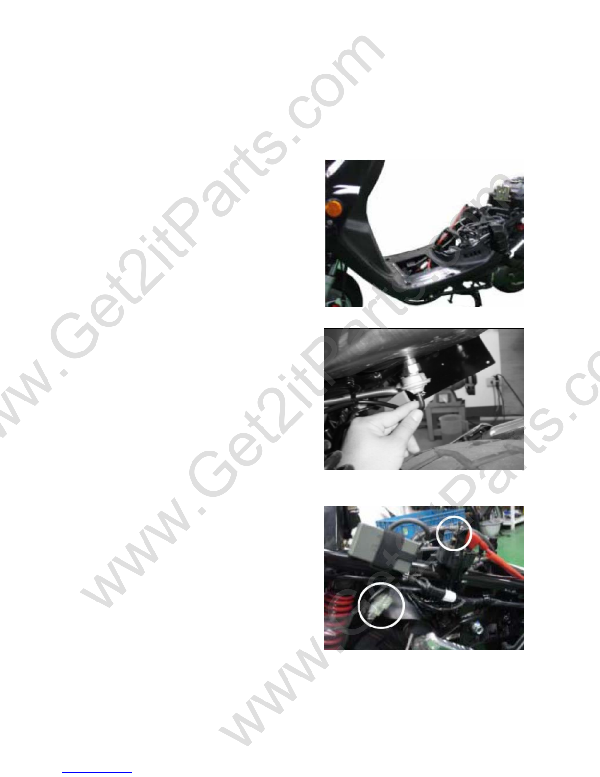
3. ENGINE REMOVAL AND INSTALLATION
3.1 ENGINE REMOVAL
Remove the seat, helmet box, and body cover.
Disconnect the oil tube, fuel tube, and vacuum tube.
Disconnect the AC generator and starter motor.
www.Get2itParts.com
www.Get2itParts.com
www.Get2itParts.com

Disconnect the carburetor and throttle cable wires.
Remove the spark plug cap.
Remove the muffler by removing the retaining bolts.
www.Get2itParts.com
www.Get2itParts.com
www.Get2itParts.com

Remove the air cleaner by removing the
retaining bolts as shown.
Remove the bolt at the bottom of the rear shock
absorber.
Remove the rear disc brake caliper bolts.
Remove the rear brake tube bolt.
www.Get2itParts.com
www.Get2itParts.com
www.Get2itParts.com

Remove engine hanger nut.
Remove the engine from the frame.
3.2 ENGINE INSTALLATION
Install engine in reverse order of disassembly.
Torque value: M8 nut: 20-30 N-m
M10 nut: 30-40 N-m
M12 nut: 50-60 N-m
After the engine is installed, check these parts:
Wires and connections
Carburetor and throttle cable
Rear brake cable
Oil tubes and fuel tubes
www.Get2itParts.com
www.Get2itParts.com
www.Get2itParts.com

4. CYLINDER HEAD AND VALVES
4.1 SERVICE INFORMATION
GENERAL
This section describes maintenance for the cylinder head, valves, camshaft, and related parts. The engine
must be removed from the frame to service cylinder head. Camshaft lubrication oil is fed to the cylinder head
through an oil orifice in the engine case. Before installing the cylinder head, be sure the orifice is not
clogged and the gasket, O-ring, and dowel pins are in place.
SPECIFICATIONS
ITEM STANDARD SERVICE LIMIT
CAM LOBE HEIGHT IN 29.795 29.395
EX 29.560 29.160
ROCKER ARM I.D. 10.000-10.018 10.10
ROCKER ARM SHAFT O.D. 9.972-9.987 9.91
CYLINDER HEAD WARPAGE 0.05
VALVE SPRING FREE LENGTH IN 32.3 31.2
OUT 35.0 34.1
VALVE STEM O.D. IN 4.975-4.990 4.90
EX 4.955-4.970 4.90
VALVE GUIDE I.D. IN/EX 5.000-5.012 5.30
STEM-TO-GUIDE CLEARANCE IN 0.010-0.037 0.08
EX 0.030-0.057 0.10
VALVE SEAT WIDTH IN 1.0 1.8
EX 1.0 1.8
TORQUE VALUES
Cylinder head bolts 10-14 N-m
Camshaft holder nuts 19-22 N-m
Tappet adjusting nut 7-11 N-m
www.Get2itParts.com
www.Get2itParts.com
www.Get2itParts.com

4.2 TROUBLE SHOOTING
Engine top-end problems usually affect engine performance. These problems can be diagnosed by a
compression test, or by tracing engine noise to the top end with a sounding rod or stethoscope.
Valve
•Incorrect valve adjustment
•Worn or damaged valve seats
•Burned or bent valve
•Incorrect valve timing
•Weak valve spring
Cylinder head
•Leaking or damaged head gasket
•Warped or cracked cylinder head
•Faulty cylinder or piston
Excessive noise
•Incorrect valve adjustment
•Sticking valve or broken valve spring
•Worn or damaged rocker arm or camshaft
•Worn or damaged cam chain
•Worn or damaged cam chain tensioner
•Worn cam sprocket teeth
Excessive smoke
•Damaged valve stem seal
•Faulty cylinder or piston rings
4.3 CAMSHAFT COMPOSITION REMOVAL
Remove the rubber tube of gas waste recovery.
Remove the cylinder head cover.
www.Get2itParts.com
www.Get2itParts.com
www.Get2itParts.com
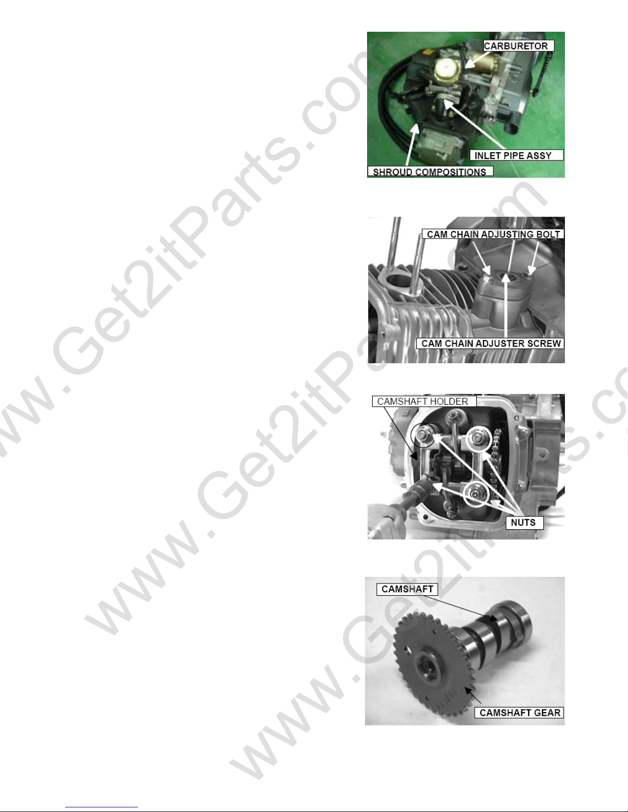
Remove the air cleaner and carburetor.
Remove the inlet pipe assembly.
Remove the shroud compositions.
Loosen the cam chain adjuster screw.
Remove the screw and O-ring and tighten the cam chain
adjusting bolt in the clockwise direction.
Remove the nuts and washers.
Remove the camshaft holder and dowel pins.
Loosen the camshaft gear from cam chain and remove
the camshaft.
www.Get2itParts.com
www.Get2itParts.com
www.Get2itParts.com
Table of contents
Other Eton America Scooter manuals


