ETT ET-BASE GSM SIM900 User manual

คู่มือการใช้งาน
ET-BASE GSM SIM900
http://www.etteam.com
Electronics Technology Team
บริษัท อีทีที จำกัด
ETT CO., LTD.

Manual of Board ET-BASE GSM SIM900
CONTENTS
1. Specifications of Board ET-BASE GSM SIM900 3
2. Initial Specifications of Module SIM900 3
3. Co positions of Board ET-BASE GSM SIM900 4
4. How to Enable/Disable Operation of Module SIM900 6
5. How to Co unicate with Module SIM900 7
6. Noteworthy Specifications of Signal 9
7. Exa ple of using AT Co and with Module SIM900 9
8. How to Test Operation of Board ET-BASE GSM SIM900 10
9. Exa ple of Using Co and about RS232 13
10. How to Setup and Check Configuration 15
11. How to Check Data of Module SIM900 16
12. How to Make, Receive, and Cancel a Call 17
13. How to Check Balance by USSD 18
14. How to Receive SMS 19
15. How to Send English SMS 20
16. Code of Thai SMS 21
17. Principles of Decoding Unicode 23
18. How to Send Thai SMS 26
19. How to Use SIM Co and (SIM Application Toolkit: STK) 28
20. How to Read Data fro Website by GPRS Connection (HTTP GET) 32
21. How to Connect Board ET-BASE GSM SIM900 with Board Microcontroller 34
ETT CO., LTD. -1- www.ettea .co

Manual of Board ET-BASE GSM SIM900
ET-BASE GSM SIM900
ET-BASE GSM SIM900 is a kit to learn and develop wireless
co unication by using Module GSM/GPRS odel SIM900 fro SIMCo to
be ain device; this SIM900 is a s all GSM/GPRS Module that supports
GSM Frequency in the range of 850/900/1800/1900MHz. It co unicates
through Port RS232 by AT Co and; it can be applied for various
applications such as trans itting/receiving signal in the for at of
Voice, SMS, Data, FAX, including Protocol TCP/IP Co unication.
Nor ally, it provides the Circuit and Fir ware internal Module
SIM900 co pletely but it is not ready to use because user has to
design the circuit of Peripheral device that is necessary to connect
with so e partial Pin of Module such as Circuit Power Supply,
circuit for connecting with SIM Card, including Circuit Line Driver
of RS232. So, ETT Tea provides the inter ediate board to connect
between Module SIM900 and external device, it assists custo er to
learn and test the operation conveniently before odifying and
adapting this Module for any application in the future. Although all
connective circuits that are provided by ETT Tea cannot support all
resources internal Module, it can support the ain capability of
this Module efficiently.
ETT CO., LTD. -2- www.ettea .co

Manual of Board ET-BASE GSM SIM900
1. Specifications of Board ET-BASE GSM SIM900
•Has Push-Button Switch to Enable/Disable the operation of
Module internal board
•Has Push-Button Switch to reset the operation of Module
internal board
•Has Socket SIM to support SIM Card with Circuit ESD to protect
SIM fro da aged
•Has 2 of isolated Regulates that can be used with Adapter 5-
12VDC; it can provide current for Module SIM900 and connective
devices enough.
oHas Circuit Regulate 4.2V/3A that can supply to Module
SIM900 enough, it can be used with SIM of GSM900MHz 2-
Watt without any proble
oHas Circuit Regulate 2.8V/150 A to supply to the circuit
that converts Signal Logic.
•Has Circuit Line Driver to convert Signal Logic fro Module
SIM900 into RS232 (1200bps-115200bps) for port co unication
that is used to co and Module.
•Has circuit to convert Signal Logic TTL 3V-5V to directly
connect with Microcontroller, without connecting through
Circuit Line Driver RS232
•Has LED to display the ready status of board; status of Power
Supply, status of Module, status of Network Connection, and
status of Power-ON/Power-OFF of Module
•Has Connector to connect with Handset ( icrophone and speaker
of ho e phone); it uses Connector Standard RJ11with Circuit
Voice Filter. In this case, it can interface Handset of ho e
phone with board through Connector RJ11 to ake and receive a
call conveniently.
2. Initial specifications of Module SIM900
•Support Frequency in the range of GSM/GPRS 850/900/1800/1900MHz
•Support GPRS Multi-Slot Class10 and GPRS Mobile Station Class B
•Support standard AT Co and (GSM 07.07/ 07.05 and additional
co ands fro SIMCOM)
•Support SIM Applications Toolkit
•Run by the Frequency in the range of 3.2V to 4.8V
•Support external connection
- Be co patible with SIM Card 1.8V and 3V
- Has Circuit Analog Audio (MIC & Speaker)
ETT CO., LTD. -3- www.ettea .co
Manual of Board ET-BASE GSM SIM900
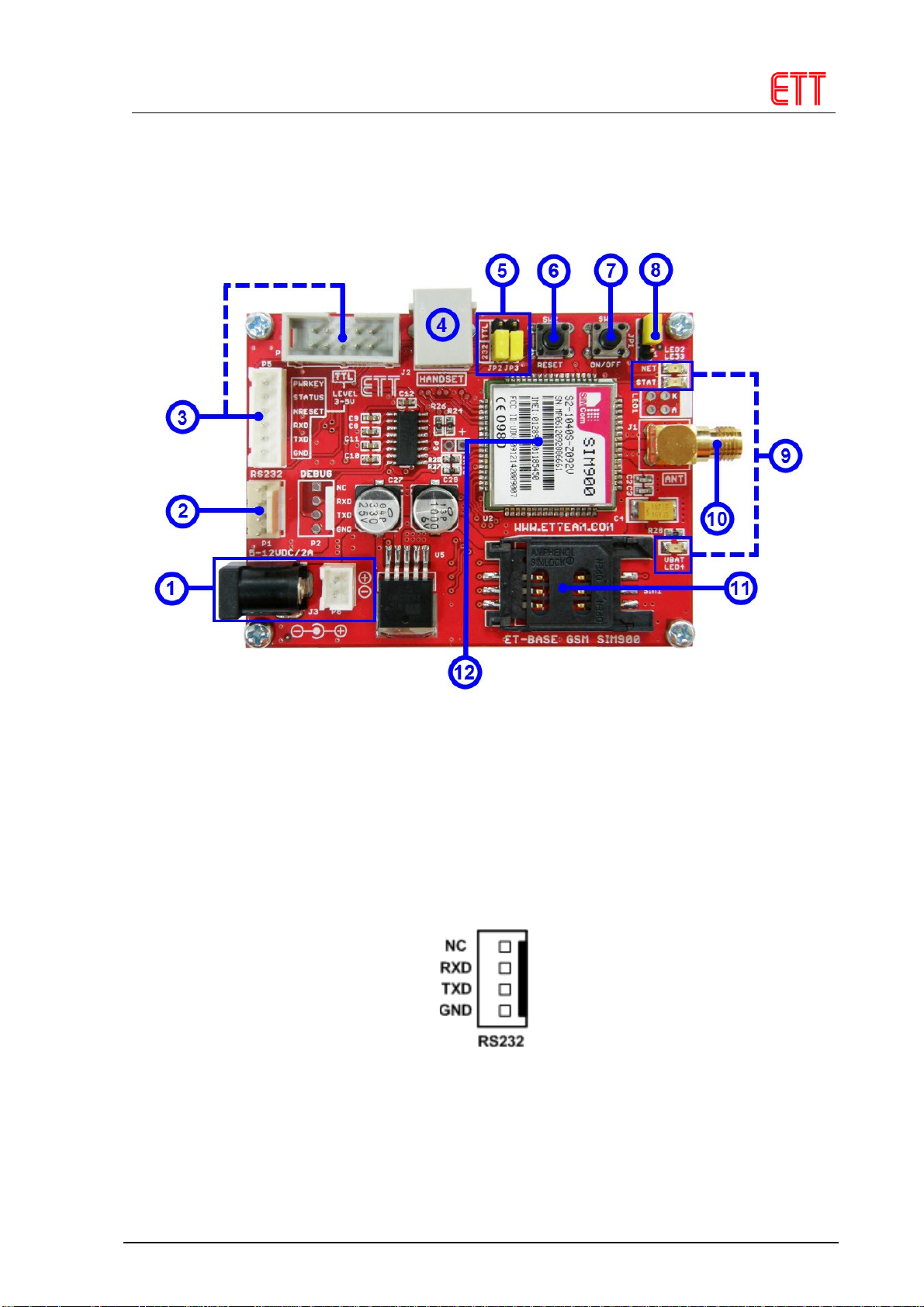
3. Co positions of Board ET-BASE GSM SIM900
•No.1: It is Connector Power Supply for board, there are 2
types. Firstly, it is DC JACK that is Anode-OUT(+) and Cathode-
IN(-); secondly, It is Connector JST. The Power Supply that
provides for board is 5-12VDC with at least 2A Current.
•No.2: It is Connector RS232 4PIN (ETT Standard); it interfaces
with device that trans its/receives data by RS232 such as
co puter or Board Microcontroller, especially be connected
through Circuit Line Driver RS232. It arranges signal pins as
shown in the picture below;
•No.3: It is Connector TTL 3.5V to connect with Microcontroller
directly, without interfacing through Circuit Line Driver
RS232. It arranges signal pins as shown in the picture below;
ETT CO., LTD. -4- www.ettea .co
Table of contents


