EUCHNER CTM-I2-BP User manual

EN
Operating Instructions
Transponder-Coded Safety Switch with Guard Locking
CTM-I2-BP/BR Unicode/Multicode

Operating Instructions
Transponder-Coded Safety Switch CTM-I2-BP/BR
2(translation of the original operating instructions) MAN20001437-01-10/21
Contents
1. About this document............................................................................................. 4
1.1. Scope............................................................................................................................................4
1.2. Target group ..................................................................................................................................4
1.3. Key to symbols...............................................................................................................................4
1.4. Supplementary documents ..............................................................................................................4
2. Correct use .......................................................................................................... 5
3. Description of the safety function .......................................................................... 6
4. Exclusion of liability and warranty ......................................................................... 7
5. General safety precautions ................................................................................... 7
6. Function............................................................................................................... 8
6.1. Guard locking for process protection................................................................................................8
6.2. Monitoring outputs/status bits .........................................................................................................8
6.2.1. Door position signal OD...................................................................................................8
6.2.2. Diagnostic signal OI.........................................................................................................8
6.2.3. Guard locking signal OL ..................................................................................................8
6.2.4. Status signal OM.............................................................................................................8
6.2.5. Locking element signal OLS.............................................................................................8
6.2.6. Communication connection C...........................................................................................8
6.3. Guard locking .................................................................................................................................9
6.3.1. Guard locking on version CTM-I2 and control via control input IMP.......................................9
6.3.2. Guard locking on version CTM-I2 and control via IO-Link communication ..............................9
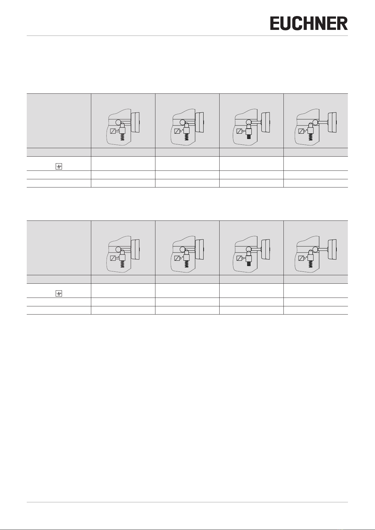
6.4. Switching states ...........................................................................................................................10
6.4.1. Switching states with control via the control input IMP......................................................10
6.4.2. Switching states with control via IO-Link communication ...................................................10
7. Manual release................................................................................................... 11
7.1. Auxiliary release............................................................................................................................11
7.1.1. Actuating auxiliary release .............................................................................................11
8. Mounting............................................................................................................ 12
9. Electrical connection .......................................................................................... 13
9.1. Notes about .........................................................................................................................14
9.2. Safety in case of faults..................................................................................................................14
9.3. Fuse protection for power supply...................................................................................................14
9.4. Requirements for connecting cables...............................................................................................14
9.5. Connector assignment of safety switch CTM-…-BR-…-SA-…
with plug connector M12, 8-pin......................................................................................................15
9.6. Notes on operation with safe control systems.................................................................................15
9.7. Connection without and with IO-Link communication.........................................................................15
9.7.1. Connection without IO-Link communication......................................................................15
9.7.2. Connection with IO-Link communication...........................................................................15

3
MAN20001437-01-10/21 (translation of the original operating instructions)
Operating Instructions
Transponder-Coded Safety Switch CTM-I2-BP/BR
EN
10. Connection of a single CTM-BP/BR (separate operation)...................................... 16
11. Connection of several devices in a switch chain (series connection) ..................... 18
11.1. Series connection with wiring in the control cabinet.........................................................................18
11.2. Series connection with Y-distributor................................................................................................18
11.2.1. Maximum cable lengths with BR switch chains.................................................................19
11.2.2. Determining cable lengths using the example table..........................................................19
11.2.3. Connector assignment of Y-distributor for series connection without IO-Link communication20
11.2.4. Connector assignment of Y-distributor for series connection with IO-Link communication ....22
12. Using communication data.................................................................................. 24
12.1. Connection to a BR/IO-Link Gateway GWY-CB..................................................................................24
12.2. Connection to a safety relay ESM-CB..............................................................................................24
12.3. Overview of the communication data ..............................................................................................24
12.3.1. Cyclical data (process data)...........................................................................................24
12.3.2. Acyclical data (device data and events)...........................................................................25
13. Setup ................................................................................................................. 26
13.1. Teach-in function for actuator (only for unicode evaluation) ...............................................................26
13.1.1. Actuator teach-in...........................................................................................................26
13.2. Functional check...........................................................................................................................27
13.2.1. Mechanical function test ................................................................................................27
13.2.2. Electrical function test...................................................................................................27
14. Factory reset...................................................................................................... 27
15. Status and error messages ................................................................................. 28
15.1. LED displays ................................................................................................................................28
15.2. Status messages..........................................................................................................................29
15.3. Error messages............................................................................................................................30
15.4. Acknowledging error messages.....................................................................................................31
16. Technical data .................................................................................................... 32
16.1. Technical data for safety switch CTM-I2 ..........................................................................................32
16.1.1. Typical system times.....................................................................................................33
16.2. Radio frequency approvals.............................................................................................................34
16.3. Dimension drawing for safety switch CTM… ...................................................................................35
16.4. Technical data for actuator A-B-A1-A1-….........................................................................................36
16.4.1. Dimension drawing for actuator A-B-A1-A1-… ..................................................................36
17. Ordering information and accessories................................................................. 37
18. Inspection and service ........................................................................................ 37
19. Service .............................................................................................................. 37
20. Declaration of conformity ................................................................................... 38

Operating Instructions
Transponder-Coded Safety Switch CTM-I2-BP/BR
4(translation of the original operating instructions) MAN20001437-01-10/21
1. About this document
1.1. Scope
These operating instructions are valid for all CTM-I2-BP/BR… from version V1.0.0. These operating instructions, the docu-
ment Safety information and any enclosed data sheet form the complete user information for your device.
1.2. Target group
Design engineers and installation planners for safety devices on machines, as well as setup and servicing staff possessing
special expertise in handling safety components.
1.3. Key to symbols
Symbol/depiction Meaning
Printed document
Internet
www Document is available for download at www.euchner.com
DANGER
WARNING
CAUTION
Safety precautions
Danger of death or severe injuries
Warning about possible injuries
Caution slight injuries possible
NOTICE
Important!
Notice about possible device damage
Important information
Tip Useful information
1.4. Supplementary documents
The overall documentation for this device consists of the following documents:
Document title
(document number) Contents
Safety information
(2525460) Basic safety information
Operating instructions
(MAN20001437) (this document)
Internet
www
Possibly enclosed data
sheet Item-specic information about deviations or additions
Important!
Always read all documents to gain a complete overview of safe installation, setup and use of the
device. The documents can be downloaded from www.euchner.com. For this purpose enter the doc.
no. in the search box.

5
MAN20001437-01-10/21 (translation of the original operating instructions)
Operating Instructions
Transponder-Coded Safety Switch CTM-I2-BP/BR
EN
2. Correct use
Safety switches series CTM-I.-… are interlocking devices with guard locking solenoid (type4) for process protection without
guard lock monitoring. The device complies with the requirements according to ENIEC60947-5-3. Devices with unicode
evaluation possess a high coding level, devices with multicode evaluation possess a low coding level.
In combination with a movable guard and the machine control, this safety component prevents dangerous machine functions
from occurring while the guard is open. A stop command is triggered if the guard is opened during the dangerous machine
function.
This means:
ÌStarting commands that cause a dangerous machine function must become active only when the guard is closed.
ÌOpening the guard triggers a stop command.
ÌClosing a guard must not cause automatic starting of a dangerous machine function. A separate start command must
be issued. For exceptions, refer to ENISO12100 or relevant C-standards.
Before the device is used, a risk assessment must be performed on the machine, e.g. in accordance with the following
standards:
ÌENISO13849-1
ÌENISO12100
ÌIEC62061
Correct use includes observing the relevant requirements for installation and operation, particularly based on the following
standards:
ÌENISO13849-1
ÌENISO14119
ÌEN60204-1
The safety switch is allowed to be operated only in conjunction with the intended EUCHNER actuator and the related connec-
tion components from EUCHNER. On the use of different actuators or other connection components, EUCHNER provides
no warranty for safe function.
Connection of several devices in a BR switch chain is permitted only using devices intended for series connection in a BR
switch chain. Check this in the specications of the device in question.
Important!
ÌThe user is responsible for the proper integration of the device into a safe overall system. For this
purpose, the overall system must be validated, e.g. in accordance with ENISO13849-2.
ÌIt is only allowed to use components that are permissible in accordance with the table below.
Table 1: Possible combinations for CTM components
Safety switch
Actuator
A-B-A1-…
CTM-… Unicode/Multicode
Key to symbols Combination possible, guard locking for process protection

Operating Instructions
Transponder-Coded Safety Switch CTM-I2-BP/BR
6(translation of the original operating instructions) MAN20001437-01-10/21
3. Description of the safety function
Devices from this series feature the following safety functions:
Monitoring of the guard position
(interlocking device with guard locking according to ENISO14119)
ÌSafety function (see chapter 6.4. Switching states on page 10):
- The safety outputs are switched off when the guard is open (monitoring of the door position).
- The following additionally applies in a BR series connection: the safety outputs are switched on only when the device
receives a corresponding signal from its predecessor in the chain.
ÌSafety characteristics: category, Performance Level, PFHD(see chapter 16. Technical data on page 32).
NOTICE
You can regard the complete BR device chain as one subsystem during calculation. The following
calculation method applies to the PFHDvalue:
#1
PFHD,1 PFHD,ext
BR-Device #1 ... n External Evaluation
(e.g. PLC)
PFHDges =∑ PFHD,k + PFHd,ext
n
k=1
#2
PFHD,2
#n
PFHD,n
Alternatively, the simplied method according to section 6.3 of EN 13849-1:2015 can be used for
calculation.

7
MAN20001437-01-10/21 (translation of the original operating instructions)
Operating Instructions
Transponder-Coded Safety Switch CTM-I2-BP/BR
EN
4. Exclusion of liability and warranty
In case of failure to comply with the conditions for correct use stated above, or if the safety regulations are not followed,
or if any servicing is not performed as required, liability will be excluded and the warranty void.
5. General safety precautions
Safety switches fulll personnel protection functions. Incorrect installation or tampering can lead to fatal injuries to personnel.
Check the safe function of the safeguard particularly
Ìafter any setup work
Ìafter the replacement of a system component
Ìafter an extended period without use
Ìafter every fault
Independent of these checks, the safe function of the safeguard should be checked at suitable intervals as part of the
maintenance schedule.
WARNING
Danger to life due to improper installation or due to bypassing (tampering). Safety components fulll
a personnel protection function.
ÌSafety components must not be bypassed, turned away, removed or otherwise rendered ineffec-
tive. On this topic pay attention in particular to the measures for reducing the possibility of bypass-
ing according to ENISO14119:2013, section 7.
ÌThe switching operation must be triggered only by actuators designated for this purpose.
ÌPrevent bypassing by means of replacement actuators (only for multicode evaluation). For this
purpose, restrict access to actuators and to keys for releases, for example.
ÌDamaged actuators can lead to limited prevention of inadvertent locking position (faulty closure
protection) when the machine is switched on. The guard locking function can no longer be ensured
if an actuator is broken. Opening the door will immediately turn off the safety outputs. Regularly
check the actuator for mechanical damage.
ÌMounting, electrical connection and setup only by authorized personnel possessing the following
knowledge:
- specialist knowledge in handling safety components
- knowledge about the applicable EMC regulations
- knowledge about the applicable regulations on operational safety and accident prevention.
Important!
Prior to use, read the operating instructions and keep these in a safe place. Ensure the operating
instructions are always available during mounting, setup and servicing. You can download the operating
instructions from www.euchner.com.

Operating Instructions
Transponder-Coded Safety Switch CTM-I2-BP/BR
8(translation of the original operating instructions) MAN20001437-01-10/21
6. Function
The device monitors the position of movable guards.
The system consists of the following components: coded actuator (transponder) and switch.
Whether the device learns the complete actuator code (unicode) or not (multicode) depends
on the respective version.
ÌDevices with unicode evaluation: The actuator must be assigned to the safety switch
by a teach-in operation so that it is detected by the system. This unambiguous assign-
ment ensures a particularly high level of protection against tampering. The system thus
possesses a high coding level.
ÌDevices with multicode evaluation: Unlike systems with unicode evaluation, on multi-
code devices a specic code is not requested but instead it is only checked whether the
actuator is of a type that can be detected by the system (multicode evaluation). There
is no exact comparison of the actuator code with the taught-in code in the safety switch
(unicode evaluation). The system possesses a low coding level.
When the guard is closed, the actuator is moved into the safety switch. When the operat-
ing distances are reached, power is supplied to the actuator by the switch and data are
transferred.
The door position signal OD is set and the safety outputs are switched on when a permissible
code is detected. Guard locking is activated when voltage is present at control input IMP.
The safety outputs are switched off and the door position signal OD is cleared when the guard is opened.
In the event of a fault in the safety switch, the safety outputs are switched off and the DIA LED illuminates red. The occurrence
of faults is detected at the latest on the next demand to close the safety outputs (e.g.on starting).
6.1. Guard locking for process protection
To prevent that, e.g., a production process is interrupted unintentionally by opening a guard, the device has guard locking
for process protection.
The position of the guard locking does not have any effect on the state of the safety outputs.
6.2. Monitoring outputs/status bits
Depending on version, the signals listed in the following are available as a status bit or at the monitoring output. The status
bits are evaluated via the BR/IO-Link Gateway. Please refer to the enclosed data sheet for further information.
6.2.1. Door position signal OD
The door position signal is sent as soon as the actuator is inserted into the switch head (state: guard closed and not locked).
The signal is also present if the guard locking is active.
6.2.2. Diagnostic signal OI
The diagnostic signal is present if there is an error (switch-on condition as for DIA LED).
6.2.3. Guard locking signal OL
The guard locking signal is present if the guard locking is active.
6.2.4. Status signal OM
The status signal is present if the device’s safety outputs are switched.
6.2.5. Locking element signal OLS
The locking element signal is present if the locking element is stuck and it is therefore not possible to activate/deactivate
guard locking. The signal is reset as soon as the actuator is no longer under tensile stress.
6.2.6. Communication connection C
A monitoring output with the sufx C has the additional function of providing a communication connection to a BR/IO-Link
Gateway. The switch delivers cyclical and acyclical data. You will nd an overview of the communication data in chapter12.
Transponder-coded
actuator
Safety switch

9
MAN20001437-01-10/21 (translation of the original operating instructions)
Operating Instructions
Transponder-Coded Safety Switch CTM-I2-BP/BR
EN
Using communication data on page 24.
If no BR/IO-Link Gateway is connected, this output behaves like a monitoring output.
6.3. Guard locking
Important!
Malfunctions due to incorrect use.
ÌThe actuator must not be under tensile stress during release.
The magnetically actuated guard locking operates in accordance with the open-circuit current principle. If the voltage is
interrupted at the solenoid, the guard locking is released and the guard can be opened directly.
The guard can be opened as long as no voltage is applied to the guard locking solenoid.
If a voltage is applied to the guard locking solenoid, the guard locking pin is held in the extended position and the guard is
locked.
6.3.1. Guard locking on version CTM-I2 and control via control input IMP
(guard locking actuated by power-ON and released by spring force)
Activating guard locking: close guard, apply voltage to control input IMP.
Releasing guard locking: interrupt voltage at control input IMP.
6.3.2. Guard locking on version CTM-I2 and control via IO-Link communication
Activating guard locking: guard locking powered by the device’s operating voltage and controlled by bitCL (bitCL=1).
Releasing guard locking: guard locking released by spring force and deactivated by bitCL (bitCL=0).

Operating Instructions
Transponder-Coded Safety Switch CTM-I2-BP/BR
10 (translation of the original operating instructions) MAN20001437-01-10/21
6.4. Switching states
6.4.1. Switching states with control via the control input IMP
The detailed switching states for your switch can be found in chapter 15. Status and error messages on page 28. All
safety outputs, signals and display LEDs are described there.
Guard closed and locked Guard closed and not locked Guard being opened Guard open
Control input IMP on off off irrelevant
Safety outputs FO1A and FO1B
on on off off
Guard locking signal OL on off off off
Door position signal OD on on on off
6.4.2. Switching states with control via IO-Link communication
Guard closed and locked Guard closed and not locked Guard being opened Guard open
Bit CL 1 0 0 irrelevant
Safety outputs FO1A and FO1B
on on off off
Guard locking signal OL on off off off
Door position signal OD on on on off

11
MAN20001437-01-10/21 (translation of the original operating instructions)
Operating Instructions
Transponder-Coded Safety Switch CTM-I2-BP/BR
EN
7. Manual release
Important!
ÌAll release functions latch when the device is electrically isolated.
ÌGuard locking remains released when the release function is reset.
Some situations require the guard locking to be released manually (e.g. malfunctions or an emergency). A function test must
be performed after release.
More information on this topic can be found in the standard ENISO14119:2013, section 5.7.5.1. The device can feature
the following release functions:
7.1. Auxiliary release
In the event of malfunctions, the guard locking can be released with the auxiliary release irre-
spective of the state of the solenoid.
The safety outputs are switched off when the auxiliary release is actuated. Use the safety
outputs to generate a stop command.
The guard locking signal OL is switched off; the door position signal OD can assume an unde-
ned state. Open the guard and close it again after resetting the auxiliary release. The device
will then operate normally again.
Important!
ÌThe actuator must not be under tensile stress during manual re-
lease.
ÌReset the auxiliary release and cover it with a new seal label after
use.
ÌLoss of the release function due to mounting errors or damage
during mounting.
ÌCheck the release function every time after mounting.
ÌAfter manual release, the solenoid must be energized briey to
re-establish guard locking.
ÌThe auxiliary release must be reset at the control system lev-
el, e.g. by means of a plausibility check (status of the safety
outputs does not match the guard locking control signal). See
ENISO14119:2013, sec. 5.7.5.4.
ÌThe auxiliary release is not a safety function.
ÌThe correct function must be checked at regular intervals.
ÌObserve the notes on any enclosed data sheets.
7.1.1. Actuating auxiliary release
1. Remove seal label or make a hole.
2. Using a screwdriver, turn the auxiliary release to in the direction of the arrow.
¨Guard locking is released.
Auxiliary re-
lease

Operating Instructions
Transponder-Coded Safety Switch CTM-I2-BP/BR
12 (translation of the original operating instructions) MAN20001437-01-10/21
8. Mounting
CAUTION
Safety switches must not be bypassed (bridging of contacts), turned away, removed or otherwise
rendered ineffective.
ÌObserve ENISO14119:2013, section 7, for information about reducing the possibilities for by-
passing an interlocking device.
NOTICE
Risk of damage to equipment and malfunctions as a result of incorrect installation.
ÌSafety switches and actuators must not be used as an end stop.
ÌObserve ENISO14119:2013, sections 5.2 and 5.3, for information about mounting the safety
switch and the actuator.
ÌProtect the switch against damage, as well as against penetrating foreign objects such as swarf,
sand and blasting shot, etc.
ÌObserve the min. door radii (see chapter 16.4.1. Dimension drawing for actuator A-B-A1-A1-… on
page 36).
ÌObserve the maximum permissible angle between switch and actuator (max. 5°).
ÌObserve the tightening torque for fastening the switch and the actuator (max. 2.9Nm).
ÌThe rear side of the switch and the actuator’s plate must lie fully on the mounting surface.
ÌActuator and safety switch must be mounted such that the actuator is vertically inserted into the
switch when the guard is closed.

13
MAN20001437-01-10/21 (translation of the original operating instructions)
Operating Instructions
Transponder-Coded Safety Switch CTM-I2-BP/BR
EN
9. Electrical connection
The following connection options are available:
ÌSeparate operation
ÌSeries connection with wiring in the control cabinet
ÌSeries connection with Y-distributor
ÌConnection without IO-Link communication
ÌConnection with IO-Link communication
WARNING
In the event of a fault, loss of the safety function due to incorrect connection.
ÌTo ensure safety, both safety outputs must always be evaluated.
ÌMonitoring outputs must not be used as safety outputs.
ÌLay the connecting cables with protection to prevent the risk of short circuits.
CAUTION
Risk of damage to equipment or malfunctions as a result of incorrect connection.
ÌDo not use a control system with pulsing or switch off the pulsing function in your control system.
The device generates its own test pulses on the safety outputs. A downstream control system
must tolerate these test pulses, which may have a length of up to 300µs.
The test pulses are output only with the safety outputs switched off during device start.
Depending on the inertia of the downstream device (control system, relay, etc.), this can lead to
short switching processes.
ÌThe inputs on a connected evaluation unit must be positive switching, as the two outputs on the
safety switch deliver a level of +24V in the switched-on state.
ÌAll the electrical connections must either be isolated from the mains supply by a safety transformer
according to IEC 61558-2-6 with limited output voltage in the event of a fault, or by other equivalent
insulation measures (PELV).
ÌAll electrical outputs must have an adequate protective circuit for inductive loads. The outputs
must be protected with a free-wheeling diode for this purpose. RC interference suppression units
must not be used.
ÌPower devices which are a powerful source of interference must be installed in a separate location
away from the input and output circuits for signal processing. The cable routing for safety circuits
should be as far away as possible from the cables of the power circuits.
ÌTo avoid EMC interference, the physical environmental and operating conditions at the installation
site of the device must comply with the requirements according to the standard EN60204-1
(EMC).
ÌPay attention to any interference elds from devices such as frequency converters or induction
heating systems. Observe the EMC instructions in the manuals from the respective manufacturer.
Important!
If the device does not appear to function when the operating voltage is applied (e.g. green STATE LED
does not ash), the safety switch must be returned to the manufacturer.

Operating Instructions
Transponder-Coded Safety Switch CTM-I2-BP/BR
14 (translation of the original operating instructions) MAN20001437-01-10/21
9.1. Notes about
Important!
ÌThis device is intended to be used with a Class 2 power source in accordance with UL1310.
As an alternative an LV/C (Limited Voltage/Current) power source with the following properties can
be used:
This device shall be used with a suitable isolating source in conjunction with a fuse in accordance
with UL248. The fuse shall be rated max. 3.3A and be installed in the max. 30 V DC power supply
to the device in order to limit the available current to comply with the UL requirements. Please note
possibly lower connection ratings for your device (refer to the technical data).
ÌFor use and application as per the requirements of UL 1) a connecting cable listed under the UL
category code CYJV/7, min. 24AWG, min. 80°C, must be used.
1) Note on the scope of the UL approval: the devices have been tested as per the requirements of UL508 and CSA/ C22.2 no. 14 (protection against electric shock
and re).
9.2. Safety in case of faults
ÌThe operating voltage UB and the control input IMP are reverse polarity protected.
ÌThe safety outputs FO1A/FO1B are short circuit-proof.
ÌA short circuit between FO1A and FO1B is detected by the switch.
ÌA short circuit in the cable can be excluded by laying the cable with protection.
9.3. Fuse protection for power supply
The power supply must be provided with fuse protection depending on the number of switches and the current required for
the outputs. The following rules apply:
Max. current consumption of an individual switch Imax
Imax = IUB + IFO1A+FO1B + IOX + IIMP
IUB = Switch operating current (max. 500mA)
IOX = Load current of monitoring outputs (max. 50mA per monitoring output)
IFO1A+FO1B = Load current of safety outputs FO1A + FO1B (2 x max. 150mA)
Important!
If there are further monitoring outputs, their load current must be taken into account.
Max. current consumption of a switch chain ΣImax
ΣImax = IFO1A+FO1B + nx (IUB + IOX)
n = Number of connected switches
9.4. Requirements for connecting cables
CAUTION
Risk of damage to equipment or malfunctions as a result of incorrect connecting cables.
ÌUse connection components and connecting cables from EUCHNER.
ÌOn the use of other connection components, the requirements in the following table apply.
EUCHNER provides no warranty for safe function in case of failure to comply with these require-
ments.

15
MAN20001437-01-10/21 (translation of the original operating instructions)
Operating Instructions
Transponder-Coded Safety Switch CTM-I2-BP/BR
EN
Observe the following requirements with respect to the connecting cables:
For safety switch CTM-…-BP/BR-…-SA-… with plug connector M12, 8-pin
Parameter Value Unit
Conductor cross-section, min. 0.25 mm²
R max. 80 W/km
C max. 120 nF/km
L max. 0.65 mH/km
Recommended cable type LIYY 8 x 0.34mm²
9.5. Connector assignment of safety switch CTM-…-BR-…-SA-…
with plug connector M12, 8-pin
Plug connector
(view of connection side) Pin Designation Function
Conductor coloring
of connecting ca-
ble 1)
1 x M12
8
5
6
7
2
4
3
1
1 FI1B Enable input, channel B WH
2 UB Electronics and solenoid operating voltage, 24V DC BN
3 FO1A Safety output, channel A GN
4 FO1B Safety output, channel B YE
5 Ox/C 2) Door position or guard lock monitoring output/communication GY
6 FI1A Enable input, channel A PK
7 0VUB Electronics and solenoid operating voltage, 0V DC BU
8 IMP Solenoid control input, 24VDC RD
1) Only for standard EUCHNER connecting cable
2) Monitoring output Ox can assume the function OD (door position) oder OL (guard locking). More detailed information about your device is available at
www.euchner.com. Simply enter the order number.
9.6. Notes on operation with safe control systems
Observe the following requirements for connection to safe control systems:
ÌUse a common power supply for the control system and the connected safety switches.
ÌA pulsed power supply must not be used for UB. Tap the supply voltage directly from the power supply unit. If the power
supply is connected to a terminal of a safe control system, this output must provide sufcient electrical current.
ÌThe safety outputs FO1A and FO1B can be connected to the safe inputs of a control system. Prerequisite: The input
must be suitable for pulsed safety signals (OSSD signals, e.g. from light grids). The control system must tolerate test
pulses on the input signals. This normally can be set up by parameter assignment in the control system. Observe the
notes of the control system manufacturer. For the test pulse duration of your safety switch, refer to chapter 16. Techni-
cal data on page 32.
ÌWith series connection: Always connect inputs FI1A and FI1B directly to a power supply unit or to outputs FO1A and
FO1B of another EUCHNER BR device. Pulsed signals must not be present at inputs FI1A and FI1B.
A detailed example of connecting and setting the parameters of the control system is available for many devices at
www.euchner.com, in the area Service/Downloads/Applications/CTM. The features of the respective device are dealt with
there in greater detail.
9.7. Connection without and with IO-Link communication
9.7.1. Connection without IO-Link communication
Only the safety and monitoring outputs are switched with this connection method.
With a series connection, the safety signals are looped through from device to device.
9.7.2. Connection with IO-Link communication
If, in addition to the safety function, detailed monitoring and diagnostic data are to be processed, a BR/IO-Link Gateway
is required. To poll the communication data from the connected device, communication connection C is routed to the BR/
IO-Link Gateway.
You will nd further information in the operating instructions for your BR/IO-Link Gateway.

Operating Instructions
Transponder-Coded Safety Switch CTM-I2-BP/BR
16 (translation of the original operating instructions) MAN20001437-01-10/21
10. Connection of a single CTM-BP/BR (separate operation)
WARNING
In the event of a fault, loss of the safety function due to incorrect connection.
ÌTo ensure safety, both safety outputs FO1A and FO1B must always be evaluated.
Important!
The example shows only an excerpt that is relevant for connection of the CTM system. The example
illustrated here does not show complete system planning. The user is responsible for safe integration
into the overall system. Detailed application examples can be found at www.euchner.com. Simply enter
the order number of your switch in the search box. You will nd all available connection examples for
the device in Downloads.
Connected load
BR evaluation
via PLC
Safety Outputs
Read Head
Actuator
CTM
Door
Monitoring
Monitoring Outputs
Diagnostic
Locking
active
FO1A
3
FO1B
4
OD/C
6
OL
7
-B1 UB
2
IMP
1
0 V
8
OI
5
13
14
-S1
1
2
-F1
1
2
-F2
24V DC
0 V
24V DC
0 V
Fig. 1: Connection example without control input IMM

17
MAN20001437-01-10/21 (translation of the original operating instructions)
Operating Instructions
Transponder-Coded Safety Switch CTM-I2-BP/BR
EN
Connected load
BR evaluation
via PLC
Safety Outputs
Read Head
Actuator
CTM
Door
Monitoring
Monitoring Outputs
Diagnostic
FO1A
3
FO1B
4
OD/C
6
IMM
8
-B1 UB
2
IMP
1
0 V
UB
7
OI
5
13
14
-S1
1
2
-F1
1
2
-F2
24V DC
0 V
24V DC
0 V
Fig. 2: Connection example with control input IMM

Operating Instructions
Transponder-Coded Safety Switch CTM-I2-BP/BR
18 (translation of the original operating instructions) MAN20001437-01-10/21
11. Connection of several devices in a switch chain (series connection)
WARNING
In the event of a fault, loss of the safety function due to incorrect connection.
ÌTo ensure safety, both safety outputs FO1A and FO1B must always be evaluated.
Important!
ÌA BR switch chain may contain a maximum of 20 safety switches.
ÌThe example shows only an excerpt that is relevant for connection of the CTM system. The exam-
ple illustrated here does not show complete system planning. The user is responsible for safe inte-
gration into the overall system. Detailed application examples can be found at www.euchner.com.
Simply enter the order number of your switch in the search box. You will nd all available connec-
tion examples for the device in Downloads.
ÌMake sure you use the correct Y-distributors. See chapter 11.2.3. Connector assignment of Y-dis-
tributor for series connection without IO-Link communication on page 20 and chapter 11.2.4.
Connector assignment of Y-distributor for series connection with IO-Link communication on page
22.
11.1. Series connection with wiring in the control cabinet
The series connection can be realized via additional terminals in a control cabinet.
The safety outputs are permanently assigned to the respective safety inputs of the downstream switch. FO1A must be routed
to FI1A and FO1B to FI1B. If the connections are interchanged (e.g. FO1A to FI1B), the device will switch to the fault state.
11.2. Series connection with Y-distributor
The series connection is shown here based on the example of the version with plug connector M12. The switches are con-
nected one behind the other with the aid of pre-assembled connecting cables and Y-distributors. If a safety door is opened
or if a fault occurs on one of the switches, the system shuts down the machine.

19
MAN20001437-01-10/21 (translation of the original operating instructions)
Operating Instructions
Transponder-Coded Safety Switch CTM-I2-BP/BR
EN
11.2.1. Maximum cable lengths with BR switch chains
Important!
The maximum number of switches in a BR switch chain depends on many factors, including the cable
length. This case example shows a standard application. You will nd further connection examples at
www.euchner.com.
SPS
PLC
l1l2
l
max
=200 m
ln
umin = 24 V
5 x 0,34 mm2
5 x 0,34 mm25 x 0,34 mm2
CTM-I2-BR # n CTM-I2-BR # n-1 CTM-I2-BR # 1
iout
11.2.2. Determining cable lengths using the example table
n
Max. number of switches depending on the cable
length
IOD (mA)
Possible output current per channel FO1A/FO1B
l1(m)
Max. cable length from the last switch to the
control system
0.34 mm²
1
10
70
25
50
100
150 60
2
10
20
25
50
100
150
3
10
20
25
50
100
150

Operating Instructions
Transponder-Coded Safety Switch CTM-I2-BP/BR
20 (translation of the original operating instructions) MAN20001437-01-10/21
11.2.3. Connector assignment of Y-distributor for series connection without IO-Link communication
Important!
ÌThe switch chain must always be terminated with a strapping plug 097645.
ÌAll guard locking solenoids are always controlled simultaneously on the use of these Y-distributors in a
series connection.
ÌA higher-level control system cannot detect which safety door is open or on which switch a fault has oc-
curred with this connection technology.
Plug connector X1 Y-distributor Plug connector X2 / X3
X1
Pin Function
X1.1 FI1B
X1.2 UB
X1.3 FO1A
X1.4 FO1B
X1.5 n.c.
X1.6 FI1A
X1.7 0VUB
X1.8 *
X1
Socket
6
5
8
4
3
2
7
1
097627
X1
X2
X3
X2
Plug
1
1
5
5
4
4
3
3
2
2
X3
Socket
X2
Pin Function
X2.1 UB
X2.2 FO1A
X2.3 0V
X2.4 FO1B
X2.5 *
X3
Pin Function
X3.1 UB
X3.2 FI1A
X3.3 0V
X3.4 FI1B
X3.5 *
X1
Socket
5
8
4
3
6
7
1
2
111696
112395
X1
X2
X3
With connecting cable
X2
Plug
5
1
43
2
5
1
4
3
2
X3
Socket
* Function and compatibility are dependent on the pin assignment of the device connected.
This manual suits for next models
1
Table of contents