Euphonic Audio iAMP DOUBLER 2 User manual
ACKNOWLEDGMENTS
Euphonic Audio would like to thank:
John Carey
MichaelArnopol
HughMcDonald
Todd VanSelus
LynnKeller
Michael Rhodes
KasimSulton
and
LelandSklar
for their invaluable contributions
to the development of the iAMP®
and this manual.
Copyright ©2016 Euphonic Audio
EUPHONICAUDIO,INC.
TOLL-FREE (609)894-3790
18 Newton Blvd •Robbinsville, NJ • 08691
Fax:(609)336-0002 •Email:info@eaamps.com
www.eaamps.com
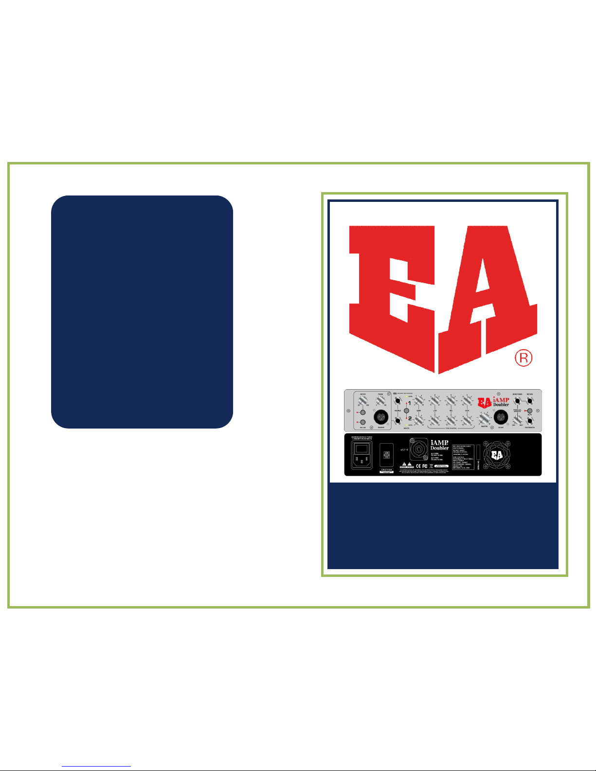
iAMP®DOUBLER 2
OPERATIONMANUAL
ACKNOWLEDGMENTS
Euphonic Audio would like to thank:
John Carey
MichaelArnopol
HughMcDonald
Todd VanSelus
LynnKeller
Michael Rhodes
KasimSulton
and
LelandSklar
for their invaluable contributions
to the development of the iAMP®
and this manual.
Copyright ©2016 Euphonic Audio
EUPHONICAUDIO,INC.
TOLL-FREE (888)894-3790
18 Newton Blvd •Robbinsville, NJ • 08691
Fax:(609)336-0002 •Email:[email protected]
www.eaamps.com
iAMP®DOUBLER 2
OPERATIONMANUAL

IMPORTANT SAFETY PRECAUTIONS
WARNING: When electrical products are
used,
basic precautions should be followed, including
:
•Read all instructions before using this
product.
•Do not use this product near water, for example, near a bathtub, sink, in a
wet
basement, near a swimming pool or the like. Prevent the unit from getting wet
from
rain, snow,
etc…
•Care should be taken so that objects do not fall, and liquids are not spilled into,
the
enclosure through the
openings.
•This product should be located so that its position or location does not interfere with
its
proper ventilation. It is important that the vents on the top, bottom, and sides of the unit
are
allowed “to
breathe.”
•The iAMP® should be located away from heat sources such as radiators,
heat
registers, or other products that produce heat
.
•Do not leave the unit in an extremely hot environment (such as inside a car)
for
extended periods of
time.
•The product should be serviced by qualified personnel
when:
-The power supply cord or the plug has been damaged;
or
-Objects have fallen, or liquid has been spilled into the product;
or
-The product has been exposed to rain or moisture;
or
-The product does not appear to operate normally or exhibits a
marked
change in performance;
or
-The product has been dropped, or the enclosure
damaged.
WARRANTY SERVICE FORM
1. Complete this
form.
2. Include a copy of your Bill of
Sale
3. Pack unit, this form and copy of original bill of sale and ship, insured
to:
Euphonic
Audio
11 Revere
Court
Princeton Jct., NJ
08550
Name:
Address:
____________________________________________________
Telephone Number:
Email:
Purchased
at: Date of
Purchase:
Model/Serial
Number
:
Brief
Description
of
Problem:
•The product should be connected to a power supply of the type described in the
operating
instructions or as
marked.
Return
Shipping:
COD:
Prepaid
Credit
Card
•If you live in area prone to frequent lightning strikes (e.g., Florida), as
a
precautionary measure, unplug the iAMP® from the AC power source,
especially
during severe
thunderstorms.
•Do not attempt to service the product yourself. All servicing should be referred
to
qualified service personnel at Euphonic Audio,
Inc.
•Use of the iAMP® may cause permanent hearing loss. Do not operate for
long
periods of time at a high volume level or at a volume level that is
uncomfortable,
particularly in a small, enclosed area. If you experience any ringing in the ears or
any
suspected hearing loss you should consult an
audiologist.
Credit Card
Number:
Expiration
Date:
If the billing address is not the same as the shipping address, please provide
billing
address:
Billing Address:
____________________________________________________
____________________________________________________
IMPORTANT SAFETY PRECAUTIONS
WARRANTY SERVICE FORM
2
3
DOUBLER SPECIFIC FEATURES
The Doubler 2 provides some specific
features designed for the
upright/acoustic player.
Notch Filter: To help with feedback, the
Doubler has a variable Notch Filter. The
Notch Filter attenuates the signal 15db from 50 to 600K at .05 octaves. THE NOTCH
FILTERISONLY AVAILABEONCHANNEL 2.
Microphone Input with Phantom Power:The Doubler has a Low Impedance Micro-
phone input with a phantom power option. The phantom power ON/OFF option is
controlled by a slide switch on the back of the preamp board (see photo). The
phantom power is ON with the switch in the left position, and OFF with the switch
in the right position. This switch is intended to be a set and forget feature. The MIC
ON switch on the front panel will turn a microphone ON and OFF and tell the ISS
circuitry that a microphone is in use.
Phase Control: The Doubler features an innovative 180 degree sweep able phase
control to adjust the phase between Channel 1 and Channel 2. This control only
works when BOTH Channel 1 and Channel2 inputs are being used.
PLEASE NOTE: If you want to use a single input and switch between 2 different EQ
settings (i.e. clean/solo) you MUST use Channel 2 as your “Master”channel
(DOUBLERONLY).
Unique Features of the iAMP® Doubler 2
The phase control can be useful when combining a pickup and a microphone or two
pickups. Anytime two different pickups or a pickup and a microphone are combined
there are phase interactions between the two. This can result with degrees of
cancellation at different frequencies. Typical phase controls can only reverse the
phase at one position. (180 degrees) The variable phase control on the Doubler offers
the flexibility to alter the phase from 0 degrees (fully counterclockwise) to 180 degrees
(fully clockwise). Experimentation is necessary to find the best sound. No two pickup
or microphone sources react the same when combined, but for the first time one is
able to fine tune the “sweet spot”. Please note that changes in the eq settings can
alter the phase relationships also. Bottom-line—experiment with the eq and phase
settings to find the best sound.
The Doubler offers a high quality microphone input. This can accommodate any low
impedance dynamic microphone or a condenser microphone that requires phantom
power. (48 volts). The phantom power switch should be in the “off”position unless
using a microphone requiring phantom power.
The notch filter on channel 2 is useful in eliminating feedback, especially when using
a microphone. A notch filter attenuates a very narrow frequency range (typically not
wider than one note). To use it, raise the volume on channel 2 until feedback begins
to occur. Then turn on the notch switch and rotate the knob until the feedback is
eliminated.
TONE SHAPING
The iAMP® Doubler 2 features a simple yet extremely musical, 3 Band EQ. The
elegant design and pristine sound of the 3 band tone shaping of the Doubler allows
for a totally neutral sound when set flat. Each band can add +/- 12dB of gain on each
channel. The low and high are shelving and the mid control is
centered around 600hz on Channel 1 and 800hz on Channel 2.
OUTPUT SECTION
Main Control: Adjusts the level going into the power amplifier section. The iAMP®
Doubler 2 was designed to be exceptionally clean, accurate and versatile. If you want
a “dirtier” overdriven-type sound, it is best to use an effects device through the
Effects loop.
Post/Pre EQ:The DI EQ can be set to send either a clean (PRE) or colored (POST)
signal created in the Tone Shaping section. See “A LookInside”for specific jumper
settings.
Mute Switch: The Mute Switch can be configured to mute the DI and/or the
Effects/Tuner Send in addition to the speaker out. The Mute Switch can be accessed
via the front panel switch or with an optional footswitch.
The red mute LED will illuminate if the Doubler is muted. Please note the amp is muted
at power on.
DI Output Jack: Balanced DI output for sending a balanced signal directly to low
noise studio equipment. The DI can be configured to either Pre (default) or Post EQ.
DOUBLER 2 FEATURES
TONE SHAPING
OUTPUT SECTION
14
15
DOUBLER SPECIFIC FEATURES
The Doubler 2 provides some specific
features designed for the
upright/acoustic player.
Notch Filter: To help with feedback, the
Doubler has a variable Notch Filter. The
Notch Filter attenuates the signal 15db from 50 to 600K at .05 octaves. THE NOTCH
FILTERISONLY AVAILABEONCHANNEL 2.
Microphone Input with Phantom Power:The Doubler has a Low Impedance Micro-
phone input with a phantom power option. The phantom power ON/OFF option is
controlled by a slide switch on the back of the preamp board (see photo). The
phantom power is ON with the switch in the left position, and OFF with the switch
in the right position. This switch is intended to be a set and forget feature. The MIC
ON switch on the front panel will turn a microphone ON and OFF and tell the ISS
circuitry that a microphone is in use.
Phase Control: The Doubler features an innovative 180 degree sweep able phase
control to adjust the phase between Channel 1 and Channel 2. This control only
works when BOTH Channel 1 and Channel2 inputs are being used.
PLEASE NOTE: If you want to use a single input and switch between 2 different EQ
settings (i.e. clean/solo) you MUST use Channel 2 as your “Master”channel
(DOUBLERONLY).
Unique Features of the iAMP® Doubler 2
The phase control can be useful when combining a pickup and a microphone or two
pickups. Anytime two different pickups or a pickup and a microphone are combined
there are phase interactions between the two. This can result with degrees of
cancellation at different frequencies. Typical phase controls can only reverse the
phase at one position. (180 degrees) The variable phase control on the Doubler offers
the flexibility to alter the phase from 0 degrees (fully counterclockwise) to 180 degrees
(fully clockwise). Experimentation is necessary to find the best sound. No two pickup
or microphone sources react the same when combined, but for the first time one is
able to fine tune the “sweet spot”. Please note that changes in the eq settings can
alter the phase relationships also. Bottom-line—experiment with the eq and phase
settings to find the best sound.
The Doubler offers a high quality microphone input. This can accommodate any low
impedance dynamic microphone or a condenser microphone that requires phantom
power. (48 volts). The phantom power switch should be in the “off”position unless
using a microphone requiring phantom power.
The notch filter on channel 2 is useful in eliminating feedback, especially when using
a microphone. A notch filter attenuates a very narrow frequency range (typically not
wider than one note). To use it, raise the volume on channel 2 until feedback begins
to occur. Then turn on the notch switch and rotate the knob until the feedback is
eliminated.
TONE SHAPING
The iAMP® Doubler 2 features a simple yet extremely musical, 3 Band EQ. The
elegant design and pristine sound of the 3 band tone shaping of the Doubler allows
for a totally neutral sound when set flat. Each band can add +/- 12dB of gain on each
channel. The low and high are shelving and the mid control is
centered around 600hz on Channel 1 and 800hz on Channel 2.
OUTPUT SECTION
Main Control: Adjusts the level going into the power amplifier section. The iAMP®
Doubler 2 was designed to be exceptionally clean, accurate and versatile. If you want
a “dirtier” overdriven-type sound, it is best to use an effects device through the
Effects loop.
Post/Pre EQ:The DI EQ can be set to send either a clean (PRE) or colored (POST)
signal created in the Tone Shaping section. See “A Look Inside”for specific jumper
settings.
Mute Switch: The Mute Switch can be configured to mute the DI and/or the
Effects/Tuner Send in addition to the speaker out. The Mute Switch can be accessed
via the front panel switch or with an optional footswitch.
The red mute LED will illuminate if the Doubler is muted. Please note the amp is muted
at power on.
DI Output Jack: Balanced DI output for sending a balanced signal directly to low
noise studio equipment. The DI can be configured to either Pre (default) or Post EQ.
DOUBLER 2 FEATURES
TONE SHAPING
OUTPUT SECTION
14
15

IMPORTANT SAFETY PRECAUTIONS
WARNING:Whenelectricalproducts are
used,
basic precautions should be followed, including
:
•Readallinstructionsbefore usingthis
product.
• Do notusethisproductnearwater,forexample,near a bathtub,sink, in a
wet
basement,near a swimmingpool or thelike.Preventtheunitfromgettingwet
from
rain,snow,
etc…
•Careshould be taken so thatobjects do notfall, andliquidsarenotspilledinto,
the
enclosurethroughthe
openings.
•Thisproductshould be located so thatitsposition or locationdoesnotinterferewith
its
properventilation. It is importantthat thevents on thetop,bottom,andsides of theunit
are
allowed“to
breathe.”
•TheiAMP®should be locatedawayfromheatsourcessuch as radiators,
heat
registers, or otherproductsthat produceheat
.
• Do notleavetheunit in an extremelyhotenvironment(such as inside a car)
for
extended periods of
time.
•Theproductshould be serviced by qualifiedpersonnel
when:
-Thepowersupplycord or theplughasbeendamaged;
or
-Objectshavefallen, or liquidhasbeenspilledintotheproduct;
or
-Theproducthasbeenexposed to rain or moisture;
or
-Theproductdoesnotappear to operatenormally or exhibits a
marked
change in performance;
or
-Theproducthasbeendropped, or theenclosure
damaged.
WARRANTYSERVICEFORM
1. Complete this
form.
2. Include acopy of your Bill of
Sale
3. Pack unit, this form and copy of original bill of sale and ship, insured
to:
Euphonic Audio Inc.
10 Brampton Way
Hamilton Square NJ 08690
Name:
Address:
____________________________________________________
TelephoneNumber:
Email:
Purchased
at:Date of
Purchase:
Model/Serial
Number
:
BriefDescription of Problem:
•Theproductshould be connectedto apowersupply of thetypedescribedin the
operating
instructionsor as
marked.
Return Shipping:COD:PrepaidCredit Card
• If youlive in areaprone to frequentlightningstrikes(e.g.,Florida), as
a
precautionarymeasure, unplug theiAMP®fromthe AC powersource,
especially
duringsevere
thunderstorms.
• Do notattempt to servicetheproductyourself.Allservicingshould be referred
to
qualifiedservicepersonnel at EuphonicAudio,
Inc.
•Use of theiAMP®maycausepermanenthearingloss. Do notoperatefor
long
periods of time at a highvolumelevel or at a volumelevelthat is
uncomfortable,
particularly in a small,enclosedarea. If youexperienceanyringing in theears or
any
suspectedhearing lossyoushouldconsult an
audiologist.
CreditCard
Number:
Expiration Date:
If the billing address is not the same as the shipping address, please provide
billing
address:
BillingAddress:
____________________________________________________
____________________________________________________
IMPORTANT SAFETY PRECAUTIONS
WARRANTY SERVICE FORM
2
3
DOUBLER SPECIFIC FEATURES
The Doubler 2 provides some specific
features designed for the
upright/acoustic player.
Notch Filter: To help with feedback, the
Doubler has a variable Notch Filter. The
Notch Filter attenuates the signal 15db from 50 to 600K at .05 octaves. THE NOTCH
FILTERISONLY AVAILABEONCHANNEL 2.
Microphone Input with Phantom Power:The Doubler has a Low Impedance Micro-
phone input with a phantom power option. The phantom power ON/OFF option is
controlled by a slide switch on the back of the preamp board (see photo). The
phantom power is ON with the switch in the left position, and OFF with the switch
in the right position. This switch is intended to be a set and forget feature. The MIC
ON switch on the front panel will turn a microphone ON and OFF and tell the ISS
circuitry that a microphone is in use.
Phase Control: The Doubler features an innovative 180 degree sweep able phase
control to adjust the phase between Channel 1 and Channel 2. This control only
works when BOTH Channel 1 and Channel2 inputs are being used.
PLEASE NOTE: If you want to use a single input and switch between 2 different EQ
settings (i.e. clean/solo) you MUST use Channel 2 as your “Master”channel
(DOUBLERONLY).
Unique Features of the iAMP® Doubler 2
The phase control can be useful when combining a pickup and a microphone or two
pickups. Anytime two different pickups or a pickup and a microphone are combined
there are phase interactions between the two. This can result with degrees of
cancellation at different frequencies. Typical phase controls can only reverse the
phase at one position. (180 degrees) The variable phase control on the Doubler offers
the flexibility to alter the phase from 0 degrees (fully counterclockwise) to 180 degrees
(fully clockwise). Experimentation is necessary to find the best sound. No two pickup
or microphone sources react the same when combined, but for the first time one is
able to fine tune the “sweet spot”. Please note that changes in the eq settings can
alter the phase relationships also. Bottom-line—experiment with the eq and phase
settings to find the best sound.
The Doubler offers a high quality microphone input. This can accommodate any low
impedance dynamic microphone or a condenser microphone that requires phantom
power. (48 volts). The phantom power switch should be in the “off”position unless
using a microphone requiring phantom power.
The notch filter on channel 2 is useful in eliminating feedback, especially when using
a microphone. A notch filter attenuates a very narrow frequency range (typically not
wider than one note). To use it, raise the volume on channel 2 until feedback begins
to occur. Then turn on the notch switch and rotate the knob until the feedback is
eliminated.
TONE SHAPING
The iAMP® Doubler 2 features a simple yet extremely musical, 3 Band EQ. The
elegant design and pristine sound of the 3 band tone shaping of the Doubler allows
for a totally neutral sound when set flat. Each band can add +/- 12dB of gain on each
channel. The low and high are shelving and the mid control is
centered around 600hz on Channel 1 and 800hz on Channel 2.
OUTPUT SECTION
Main Control: Adjusts the level going into the power amplifier section. The iAMP®
Doubler 2 was designed to be exceptionally clean, accurate and versatile. If you want
a “dirtier” overdriven-type sound, it is best to use an effects device through the
Effects loop.
Post/Pre EQ:The DI EQ can be set to send either a clean (PRE) or colored (POST)
signal created in the Tone Shaping section. See “A Look Inside”for specific jumper
settings.
Mute Switch: The Mute Switch can be configured to mute the DI and/or the
Effects/Tuner Send in addition to the speaker out. The Mute Switch can be accessed
via the front panel switch or with an optional footswitch.
The red mute LED will illuminate if the Doubler is muted. Please note the amp is muted
at power on.
DI Output Jack: Balanced DI output for sending a balanced signal directly to low
noise studio equipment. The DI can be configured to either Pre (default) or Post EQ.
DOUBLER 2 FEATURES
TONE SHAPING
OUTPUT SECTION
14
15

EA’S QUALITY CONTROL
To ensure your iAMP® meets its rigid design specifications:
•Every board is pre-tested before it is installed into the amp.
•Post assembly, each iAMP® is bench-tested before its burn-in phase.
•Each unit is burned-in (turned on and allowed to sit “in idle”).
•Each unit is individually tested with a bass and speaker cabinets.
Additionally, the preamplifier section uses state-of-the-art surface mount components
and construction techniques for lower noise and better reliably. These extensive and
time consuming procedures guarantee that EA’s production units are of a consistently
high quality. Careful packaging helps ensure safe transport to the customer.
WARRANTY SERVICE INFORMATION
There is no need to register your product at time of purchase. However, you may
register your product at www.eaamps.com. For warranty service you will need to
have your original bill of sale.
Please follow these steps if your Amplifier or Speaker Cabinet requires repair:
1. Locate your original Bill of Sale which should include date and place of
purchase.
2. Call, FAX, write or email Euphonic Audio describing the problem. Many
issues can be handled without having to return the unit.
3. Pack the unit carefully, preferably in its original shipping carton, enclose the
attached warranty service form, and a copy of the Bill of Sale. Ship the unit,
prepaid, to the factory. Please be sure to properly insure the unit when
shipping it.
4. It is the responsibility of the purchaser to pay shipping to and from the
Euphonic Audio repair facility.
5. If it is determined that the unit is under warranty, we will repair the unit as
deemed appropriate (repair or replacement parts) free of charge. The unit will
be returned by either COD or by prepaid credit card for actual shipping
charges.
6. If it is determined that the unit is not under warranty, EA will notify you of
the repair cost. Upon your approval we will return the repaired unit COD for
the cost of repair, shipping and insurance.
WARNINGS USED ON THE EQUIPMENT
WARNING–ATTENTION OUTLETSWITHATHIRDPRONG GROUNDARE
REQUIRED. DO NOT USE WITHOUT A GROUNDING PLUG.
WARNING TO REDUCE THE RISK OF FIRE OR ELECTRIC SHOCK, DO NOT
EXPOSE THIS APPARATUS TO RAIN OR MOISTURE.
The lightning flash symbol is intended to alert the user to the
presence of uninsulated “dangerous voltage” within this
product’s enclosure that may be of sufficient magnitude to
constitute risk of electric shock.
The unit contains no user serviceable components, under no circumstances should
the unit be turned on or plugged in with the top cover removed.
The exclamation point is intended to alert the user to the pres-
ence of important operating and maintenance (servicing)
instructions in the literature accompanying this product.
GROUNDING INSTRUCTIONS This product must be grounded. If it should
malfunction or break down, grounding provides a path of least resistance for
electric current to travel, which will reduce the risk of electric shock. The product
is equipped with a power cord having an equipment grounding conductor and
a grounding plug. It must be plugged into an appropriate outlet that is properly
installed and grounded in accordance with local codes and ordinances.
DANGER Improper connection, lack of connection, or modification of the
equipment grounding conductor can result in a risk of electric shock. Check with a
qualified electrician or serviceperson if you are in doubt as to when the product is
properly grounded. Do not modify the plug provided with the product if it will not
fit an outlet; instead, have a proper outlet installed.
Make sure that the speaker connections and AC power connections are both
properly made before powering on the amplifier. Likewise, power off the amplifier
before disconnecting the speaker connections and before removing the AC power
cord from the rear connecto
EA’S QUALITY CONTROL
WARNINGS USED ON THE EQUIPMENT
WARRANTY SERVICE INFORMATION
4
5
EFFECTS SECTION
The default setting for the Effects/Tuner Send and Return makes it available on
Channels 1 and 2 (see “A Look Inside”). Via jumper settings the Effects/Tuner Send
and Return can be available on both channels. This can be changed as a custom
configuration only.
Parallel Effects/Tuner Send Jack: Connect the
cord going to the effects box, pedal or tuner
here.
Dry/Wet Control: Use this control to adjust the
level of the signal returning from the effects
chain.
Footswitch: An optional mono or dual momentary footswitch can be plugged into the
footswitch jack. When using a mono footswitch you will be able to control the IIS
channel switching function as you would with the front panel switch. When using a
dual momentary footswitch (with a stereo plug) you can additionally control the mute
function as you would with the front panel switch. The footswitch does not disable
the front panel controls; rather they continue to work in parallel and picks up where
one leaves off. With a dual footswitch the “tip” controls the IIS while the “ring”
controls muting functions. The configuration of the Footswitch is handled by
S7. See “A Look Inside”for specific jumper settings. The factory default setting is for a
mono footswitch.
REAR PANEL FUNCTIONS
INPUT SECTION
Source: Two, 1 MEG Ohm, instrument inputs designed for maximum flexibility for all
musical instrument applications. On channel 2, one optional low impedance Microphone
input with phantom power may be used in place of the ¼” instrument input.
IIS or Intelligent Input Switching, which can be actuated from the front panel or with
an optional footswitch, is a microprocessor controlled CIRCUIT that senses which
channel is activated and allows for different combinations of channel control. With
your bass plugged into channel 1, the switch will let you access the EQ on channel 1
or channel 2 (i.e. clean/solo). With basses plugged into channels 1 and 2, the IIS will
toggle between Channel 1, Channel 2, or both Channels 1 and 2.
Level Indicator Yellow LED: The Level Indicator LED is a visual representation of
your input level. The LED should illuminate moderately under normal playing
conditions. Input gain can be adjusted with the Gain control knob.
Gain Knobs: The Gain knobs allow for maximum signal level and headroom. Gain for
each channel can be adjusted by the Gain knob located on top of the amp.
Power Switch: Turns unit on/off.
A/C Input: Use appropriately grounded, three-prong A/C plug.
Speaker Output: One Speakonconnectors, wired 1+, 1-.
Cooling Vents: The vents on the top and sides of your Micro or Doubler need
to be kept clear.
Using the Gain Knobs: The yellow LED for each channel
should illuminate moderately under normal playing
conditions with the gain knob about half way up
EFFECTS SECTION
REAR PANEL FUNCTIONS
INPUT SECTION
12
13
EFFECTS SECTION
The default setting for the Effects/Tuner Send and Return makes it available on
Channels 1 and 2 (see “A Look Inside”). Via jumper settings the Effects/Tuner Send
and Return can be available on both channels. This can be changed as a custom
configuration only.
Parallel Effects/Tuner Send Jack: Connect the
cord going to the effects box, pedal or tuner
here.
Dry/Wet Control: Use this control to adjust the
level of the signal returning from the effects
chain.
Footswitch: An optional mono or dual momentary footswitch can be plugged into the
footswitch jack. When using a mono footswitch you will be able to control the IIS
channel switching function as you would with the front panel switch. When using a
dual momentary footswitch (with a stereo plug) you can additionally control the mute
function as you would with the front panel switch. The footswitch does not disable
the front panel controls; rather they continue to work in parallel and picks up where
one leaves off. With a dual footswitch the “tip” controls the IIS while the “ring”
controls muting functions. The configuration of the Footswitch is handled by
S7. See “A Look Inside”for specific jumper settings. The factory default setting is for a
mono footswitch.
REAR PANEL FUNCTIONS
INPUT SECTION
Source: Two, 1 MEG Ohm, instrument inputs designed for maximum flexibility for all
musical instrument applications. On channel 2, one optional low impedance Microphone
input with phantom power may be used in place of the ¼” instrument input.
IIS or Intelligent Input Switching, which can be actuated from the front panel or with
an optional footswitch, is a microprocessor controlled CIRCUIT that senses which
channel is activated and allows for different combinations of channel control. With
your bass plugged into channel 1, the switch will let you access the EQ on channel 1
or channel 2 (i.e. clean/solo). With basses plugged into channels 1 and 2, the IIS will
toggle between Channel 1, Channel 2, or both Channels 1 and 2.
Level Indicator Yellow LED: The Level Indicator LED is a visual representation of
your input level. The LED should illuminate moderately under normal playing
conditions. Input gain can be adjusted with the Gain control knob.
Gain Knobs: The Gain knobs allow for maximum signal level and headroom. Gain for
each channel can be adjusted by the Gain knob located on top of the amp.
Power Switch: Turns unit on/off.
A/C Input: Use appropriately grounded, three-prong A/C plug.
Speaker Output: One Speakonconnectors, wired 1+, 1-.
Cooling Vents: The vents on the top and sides of your Micro or Doubler need
to be kept clear.
Using the Gain Knobs: The yellow LED for each channel
should illuminate moderately under normal playing
conditions with the gain knob about half way up
EFFECTS SECTION
REAR PANEL FUNCTIONS
INPUT SECTION
12
13

EA’S QUALITY CONTROL
To ensure your iAMP® meets its rigid design specifications:
•Every board is pre-tested before it is installed into the amp.
•Post assembly, each iAMP® is bench-tested before its burn-in phase.
•Each unit is burned-in (turned on and allowed to sit “in idle”).
•Each unit is individually tested with a bass and speaker cabinets.
Additionally, the preamplifier section uses state-of-the-art surface mount components
and construction techniques for lower noise and better reliably. These extensive and
time consuming procedures guarantee that EA’s production units are of a consistently
high quality. Careful packaging helps ensure safe transport to the customer.
WARRANTY SERVICE INFORMATION
There is no need to register your product at time of purchase. However, you may
register your product at www.eaamps.com. For warranty service you will need to
have your original bill of sale.
Please follow these steps if your Amplifier or Speaker Cabinet requires repair:
1. Locate your original Bill of Sale which should include date and place of
purchase.
2. Call, FAX, write or email Euphonic Audio describing the problem. Many
issues can be handled without having to return the unit.
3. Pack the unit carefully, preferably in its original shipping carton, enclose the
attached warranty service form, and a copy of the Bill of Sale. Ship the unit,
prepaid, to the factory. Please be sure to properly insure the unit when
shipping it.
4. It is the responsibility of the purchaser to pay shipping to and from the
Euphonic Audio repair facility.
5. If it is determined that the unit is under warranty, we will repair the unit as
deemed appropriate (repair or replacement parts) free of charge. The unit will
be returned by either COD or by prepaid credit card for actual shipping
charges.
6. If it is determined that the unit is not under warranty, EA will notify you of
the repair cost. Upon your approval we will return the repaired unit COD for
the cost of repair, shipping and insurance.
WARNINGS USED ON THE EQUIPMENT
WARNING–ATTENTION OUTLETSWITHATHIRDPRONG GROUNDARE
REQUIRED. DO NOT USE WITHOUT A GROUNDING PLUG.
WARNING TO REDUCE THE RISK OF FIRE OR ELECTRIC SHOCK, DO NOT
EXPOSE THIS APPARATUS TO RAIN OR MOISTURE.
The lightning flash symbol is intended to alert the user to the
presence of uninsulated “dangerous voltage” within this
product’s enclosure that may be of sufficient magnitude to
constitute risk of electric shock.
The unit contains no user serviceable components, under no circumstances should
the unit be turned on or plugged in with the top cover removed.
The exclamation point is intended to alert the user to the pres-
ence of important operating and maintenance (servicing)
instructions in the literature accompanying this product.
GROUNDING INSTRUCTIONS This product must be grounded. If it should
malfunction or break down, grounding provides a path of least resistance for
electric current to travel, which will reduce the risk of electric shock. The product
is equipped with a power cord having an equipment grounding conductor and
a grounding plug. It must be plugged into an appropriate outlet that is properly
installed and grounded in accordance with local codes and ordinances.
DANGER Improper connection, lack of connection, or modification of the
equipment grounding conductor can result in a risk of electric shock. Check with a
qualified electrician or serviceperson if you are in doubt as to when the product is
properly grounded. Do not modify the plug provided with the product if it will not
fit an outlet; instead, have a proper outlet installed.
Make sure that the speaker connections and AC power connections are both
properly made before powering on the amplifier. Likewise, power off the amplifier
before disconnecting the speaker connections and before removing the AC power
cord from the rear connecto
EA’S QUALITY CONTROL
WARNINGS USED ON THE EQUIPMENT
WARRANTY SERVICE INFORMATION
4
5
EA’S QUALITY CONTROL
To ensure your iAMP® meets its rigid design specifications:
•Every board is pre-tested before it is installed into the amp.
•Post assembly, each iAMP® is bench-tested before its burn-in phase.
•Each unit is burned-in (turned on and allowed to sit “in idle”).
•Each unit is individually tested with a bass and speaker cabinets.
Additionally, the preamplifier section uses state-of-the-art surface mount components
and construction techniques for lower noise and better reliably. These extensive and
time consuming procedures guarantee that EA’s production units are of a consistently
high quality. Careful packaging helps ensure safe transport to the customer.
WARRANTY SERVICE INFORMATION
There is no need to register your product at time of purchase. However, you may
register your product at www.eaamps.com. For warranty service you will need to
have your original bill of sale.
Please follow these steps if your Amplifier or Speaker Cabinet requires repair:
1. Locate your original Bill of Sale which should include date and place of
purchase.
2. Call, FAX, write or email Euphonic Audio describing the problem. Many
issues can be handled without having to return the unit.
3. Pack the unit carefully, preferably in its original shipping carton, enclose the
attached warranty service form, and a copy of the Bill of Sale. Ship the unit,
prepaid, to the factory. Please be sure to properly insure the unit when
shipping it.
4. It is the responsibility of the purchaser to pay shipping to and from the
Euphonic Audio repair facility.
5. If it is determined that the unit is under warranty, we will repair the unit as
deemed appropriate (repair or replacement parts) free of charge. The unit will
be returned by either COD or by prepaid credit card for actual shipping
charges.
6. If it is determined that the unit is not under warranty, EA will notify you of
the repair cost. Upon your approval we will return the repaired unit COD for
the cost of repair, shipping and insurance.
WARNINGS USED ON THE EQUIPMENT
WARNING–ATTENTION OUTLETSWITHATHIRDPRONG GROUNDARE
REQUIRED. DO NOT USE WITHOUT A GROUNDING PLUG.
WARNING TO REDUCE THE RISK OF FIRE OR ELECTRIC SHOCK, DO NOT
EXPOSE THIS APPARATUS TO RAIN OR MOISTURE.
The lightning flash symbol is intended to alert the user to the
presence of uninsulated “dangerous voltage” within this
product’s enclosure that may be of sufficient magnitude to
constitute risk of electric shock.
The unit contains no user serviceable components, under no circumstances should
the unit be turned on or plugged in with the top cover removed.
The exclamation point is intended to alert the user to the pres-
ence of important operating and maintenance (servicing)
instructions in the literature accompanying this product.
GROUNDING INSTRUCTIONS This product must be grounded. If it should
malfunction or break down, grounding provides a path of least resistance for
electric current to travel, which will reduce the risk of electric shock. The product
is equipped with a power cord having an equipment grounding conductor and
a grounding plug. It must be plugged into an appropriate outlet that is properly
installed and grounded in accordance with local codes and ordinances.
DANGER Improper connection, lack of connection, or modification of the
equipment grounding conductor can result in a risk of electric shock. Check with a
qualified electrician or serviceperson if you are in doubt as to when the product is
properly grounded. Do not modify the plug provided with the product if it will not
fit an outlet; instead, have a proper outlet installed.
Make sure that the speaker connections and AC power connections are both
properly made before powering on the amplifier. Likewise, power off the amplifier
before disconnecting the speaker connections and before removing the AC power
cord from the rear connecto
EA’S QUALITY CONTROL
WARNINGS USED ON THE EQUIPMENT
WARRANTY SERVICE INFORMATION
4
5
EFFECTS SECTION
The default setting for the Effects/Tuner Send and Return makes it available on
Channels 1 and 2 (see “A Look Inside”). Via jumper settings the Effects/Tuner Send
and Return can be available on both channels. This can be changed as a custom
configuration only.
Parallel Effects/Tuner Send Jack: Connect the
cord going to the effects box, pedal or tuner
here.
Dry/Wet Control: Use this control to adjust the
level of the signal returning from the effects
chain.
Footswitch: An optional mono or dual momentary footswitch can be plugged into the
footswitch jack. When using a mono footswitch you will be able to control the IIS
channel switching function as you would with the front panel switch. When using a
dual momentary footswitch (with a stereo plug) you can additionally control the mute
function as you would with the front panel switch. The footswitch does not disable
the front panel controls; rather they continue to work in parallel and picks up where
one leaves off. With a dual footswitch the “tip” controls the IIS while the “ring”
controls muting functions. The configuration of the Footswitch is handled by
S7. See “A Look Inside”for specific jumper settings. The factory default setting is for a
mono footswitch.
REAR PANEL FUNCTIONS
INPUT SECTION
Source: Two, 1 MEG Ohm, instrument inputs designed for maximum flexibility for all
musical instrument applications. On channel 2, one optional low impedance Microphone
input with phantom power may be used in place of the ¼” instrument input.
IIS or Intelligent Input Switching, which can be actuated from the front panel or with
an optional footswitch, is a microprocessor controlled CIRCUIT that senses which
channel is activated and allows for different combinations of channel control. With
your bass plugged into channel 1, the switch will let you access the EQ on channel 1
or channel 2 (i.e. clean/solo). With basses plugged into channels 1 and 2, the IIS will
toggle between Channel 1, Channel 2, or both Channels 1 and 2.
Level Indicator Yellow LED: The Level Indicator LED is a visual representation of
your input level. The LED should illuminate moderately under normal playing
conditions. Input gain can be adjusted with the Gain control knob.
Gain Knobs: The Gain knobs allow for maximum signal level and headroom. Gain for
each channel can be adjusted by the Gain knob located on top of the amp.
Power Switch: Turns unit on/off.
A/C Input: Use appropriately grounded, three-prong A/C plug.
Speaker Output: One Speakonconnectors, wired 1+, 1-.
Cooling Vents: The vents on the top and sides of your Micro or Doubler need
to be kept clear.
Using the Gain Knobs: The yellow LED for each channel
should illuminate moderately under normal playing
conditions with the gain knob about half way up
EFFECTS SECTION
REAR PANEL FUNCTIONS
INPUT SECTION
12
13
EFFECTS SECTION
The default setting for the Effects/Tuner Send and Return makes it available on
Channels 1 and 2 (see “A Look Inside”). Via jumper settings the Effects/Tuner Send
and Return can be available on both channels. This can be changed as a custom
configuration only.
Parallel Effects/Tuner Send Jack: Connect the
cord going to the effects box, pedal or tuner
here.
Dry/Wet Control: Use this control to adjust the
level of the signal returning from the effects
chain.
Footswitch: An optional mono or dual momentary footswitch can be plugged into the
footswitch jack. When using a mono footswitch you will be able to control the IIS
channel switching function as you would with the front panel switch. When using a
dual momentary footswitch (with a stereo plug) you can additionally control the mute
function as you would with the front panel switch. The footswitch does not disable
the front panel controls; rather they continue to work in parallel and picks up where
one leaves off. With a dual footswitch the “tip” controls the IIS while the “ring”
controls muting functions. The configuration of the Footswitch is handled by
S7. See “A Look Inside”for specific jumper settings. The factory default setting is for a
mono footswitch.
REAR PANEL FUNCTIONS
INPUT SECTION
Source: Two, 1 MEG Ohm, instrument inputs designed for maximum flexibility for all
musical instrument applications. On channel 2, one optional low impedance Microphone
input with phantom power may be used in place of the ¼” instrument input.
IIS or Intelligent Input Switching, which can be actuated from the front panel or with
an optional footswitch, is a microprocessor controlled CIRCUIT that senses which
channel is activated and allows for different combinations of channel control. With
your bass plugged into channel 1, the switch will let you access the EQ on channel 1
or channel 2 (i.e. clean/solo). With basses plugged into channels 1 and 2, the IIS will
toggle between Channel 1, Channel 2, or both Channels 1 and 2.
Level Indicator Yellow LED: The Level Indicator LED is a visual representation of
your input level. The LED should illuminate moderately under normal playing
conditions. Input gain can be adjusted with the Gain control knob.
Gain Knobs: The Gain knobs allow for maximum signal level and headroom. Gain for
each channel can be adjusted by the Gain knob located on top of the amp.
Power Switch: Turns unit on/off.
A/C Input: Use appropriately grounded, three-prong A/C plug.
Speaker Output: One Speakonconnectors, wired 1+, 1-.
Cooling Vents: The vents on the top and sides of your Micro or Doubler need
to be kept clear.
Using the Gain Knobs: The yellow LED for each channel
should illuminate moderately under normal playing
conditions with the gain knob about half way up
EFFECTS SECTION
REAR PANEL FUNCTIONS
INPUT SECTION
12
13

JP3 JP4
C 1
Trim
Pot
C 2
Trim
Pot
HPF
Trim
Pot
DI
Out
Specifications
Model iAMP®Doubler 2
Type: Solid State, Integrated Musical Instrument
Amplifier with Class D Power Amp and Switching
Power Supply
Power: 450 watts RMS@8 ohms, 625
watts RMS@4 ohms,
A LOOK INSIDE
In order to make the iAMP Micro and Doubler the smallest and most versatile musical
instrument amplifiers on the market, EA has designed in three levels of configuration/
adjustment. The first two levels, the front panel and the top mounted trim pots have
already been examined. The third level of configuration represents one time settings
that reflect the way you play and your setup. There are no user serviceable parts
inside the iAMP, an authorized EA dealer can configure your iAMP® Doubler2 to suit
your playing needs and styles.
Location of Jumpers and Trim Pots as viewed from the top of the Micro and Doubler
Jumper location illustration (from top looking down)
Line Voltage: 85-132; 170-264 selectable
JP2 JP6
Weight: Doubler 4 pounds
Country of Manufacture: United States of America
There are four internal jumpers (JP2, JP3, JP4 and JP6) that can be configured as
follows:
JP2 - Assigns Channel 2 to the Effects Send circuitry. Channel 1 is always there no matter what
position the jumper is in. Repositioning the jumper adds channel 2.
Euphonic Audio, Inc. reserves the right to modify design
or specifications when deemed necessary, or when
materials or procedures dictate.
Jumper on JP2 pins 1 & 2 =
Channels
1 & 2 (DEFAULT)
Jumper on JP2 pins 2 & 3 =
Channels 1 only
JP3 - Assigns the DI signal to either pre (clean) or post (colored) EQ.
Jumper on JP3 pins 3 & 5 = DI is
post EQ
Jumper on JP3 pins 4 & 6 = DI is
pre EQ (DEFAULT)
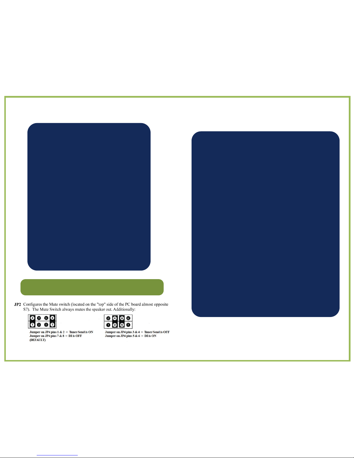
JP4 - Configures the Mute Switch. The Mute Switch always mutes the speaker out. Additionally:
Jumper on JP4 pins 1 & 2 = Tuner/Send is ON
Jumper on JP4 pins 7 & 8 = DI is OFF
(DEFAULT)
Jumper on JP4 pins 3 & 4 = Tuner/Send is OFF
Jumper on JP4 pins 5 & 6 = DI is ON
JP6 - Configures the function of the Footswitch
JP4 –Configures the Mute Switch. The Mute Switch always mutes the speaker out. Additionally:
Jumper on JP4 pins 1 & 2 = Tuner/Send is ON
Jumper on JP4 pins 7 & 8 = DI is OFF
(DEFAULT)
Jumper on JP4 pins 3 & 4 = Tuner/Send is OFF
Jumper on JP4 pins 5 & 6 = DI is ON
10
11
A LOOK INSIDE
A NOTE FROM
EUPHONIC
A
UDIO
Thank you for purchasing the EA® iAMP®
Integrated
Musical
Instrument
Amplifier.
We’re extremely proud of our iAMP® and
pleased that you have chosen it.
You will receive many years of satisfaction
from your iAMP®, which has been carefully
designed to create accurate and exceptional
sound from any musical instrument.
Our confidence is the result of an extensive
research and development program, our
innovative design philosophy, the use of the
finest quality components and state of
the art
manufacturing. Every EA product incor-
porates the input from the many talented
and respected musicians who use EA’s
other products, from the critically acclaimed
Wizzy 12 to the “classic” iAMP 800 and
our one-of-a-kind RUMBLE SEAT™.
LIMITED WARRANTY
The warranty for Euphonic Audio Amplifiers and Speaker Cabinets is
THREE YEARS from the date of purchase. This covers defects in material
and workmanship for the ORIGINAL owner.
The warranty is void under the following conditions:
•If the unit has been damaged due to accident, improper
handling, installation or operation
• If the unit has been damaged in shipping
•Abuse or misuse. This includes exceeding the physical limitations
of amplifier or speaker cabinet, i.e. using excessive bass boost in
the Wizzy 10.
• Unauthorized repair or attempted repair
• If the serial number has been defaced or removed
Euphonic Audio, Inc. reserves the right to make such determination of the
above on the basis of factory inspection.
All liability for any incidental or consequential damage for breach or any
expressed or implied warranties is disclaimed and excluded here from.
Some states do not allow limitations on how long an implied warranty lasts,
or the exclusion or limitation of incidental and/or consequential damages, so
that the above limitation or exclusion may not apply to you. This warranty
gives specific legal rights and you may also have other rights, which vary
from state to state.
6
7
JP3 JP4
C 1
Trim
Pot
C 2
Trim
Pot
HPF
Trim
Pot
DI
Out
Specifications
Model iAMP®Doubler 2
Type: Solid State, Integrated Musical Instrument
Amplifier with Class D Power Amp and Switching
Power Supply
Power: 450 watts RMS@8 ohms, 625
watts RMS@4 ohms,
A LOOK INSIDE
In order to make the iAMP Micro and Doubler the smallest and most versatile musical
instrument amplifiers on the market, EA has designed in three levels of configuration/
adjustment. The first two levels, the front panel and the top mounted trim pots have
already been examined. The third level of configuration represents one time settings
that reflect the way you play and your setup. There are no user serviceable parts
inside the iAMP, an authorized EA dealer can configure your iAMP® Doubler2 to suit
your playing needs and styles.
Location of Jumpers and Trim Pots as viewed from the top of the Micro and Doubler
Jumper location illustration (from top looking down)
Line Voltage: 85-132; 170-264 selectable
JP2 JP6
Weight: Doubler 4 pounds
Country of Manufacture: United States of America
There are four internal jumpers (JP2, JP3, JP4 and JP6) that can be configured as
follows:
JP2 - Assigns Channel 2 to the Effects Send circuitry. Channel 1 is always there no matter what
position the jumper is in. Repositioning the jumper adds channel 2.
Euphonic Audio, Inc. reserves the right to modify design
or specifications when deemed necessary, or when
materials or procedures dictate.
Jumper on JP2 pins 1 & 2 =
Channels
1 & 2 (DEFAULT)
Jumper on JP2 pins 2 & 3 =
Channels 1 only
JP3 - Assigns the DI signal to either pre (clean) or post (colored) EQ.
Jumper on JP3 pins 3 & 5 = DI is
post EQ
Jumper on JP3 pins 4 & 6 = DI is
pre EQ (DEFAULT)
JP4 - Configures the Mute Switch. The Mute Switch always mutes the speaker out. Additionally:
Jumper on JP4 pins 1 & 2 = Tuner/Send is ON
Jumper on JP4 pins 7 & 8 = DI is OFF
(DEFAULT)
Jumper on JP4 pins 3 & 4 = Tuner/Send is OFF
Jumper on JP4 pins 5 & 6 = DI is ON
JP6 - Configures the function of the Footswitch
JP4 –Configures the Mute Switch. The Mute Switch always mutes the speaker out. Additionally:
Jumper on JP4 pins 1 & 2 = Tuner/Send is ON
Jumper on JP4 pins 7 & 8 = DI is OFF
(DEFAULT)
Jumper on JP4 pins 3 & 4 = Tuner/Send is OFF
Jumper on JP4 pins 5 & 6 = DI is ON
10
11
A LOOK INSIDE
A NOTE FROM
EUPHONIC
A
UDIO
Thank you for purchasing the EA® iAMP®
Integrated
Musical
Instrument
Amplifier.
We’re extremely proud of our iAMP® and
pleased that you have chosen it.
You will receive many years of satisfaction
from your iAMP®, which has been carefully
designed to create accurate and exceptional
sound from any musical instrument.
Our confidence is the result of an extensive
research and development program, our
innovative design philosophy, the use of the
finest quality components and state of
the art
manufacturing. Every EA product incor-
porates the input from the many talented
and respected musicians who use EA’s
other products, from the critically acclaimed
Wizzy 12 to the “classic” iAMP 800 and
our one-of-a-kind RUMBLE SEAT™.
LIMITED WARRANTY
The warranty for Euphonic Audio Amplifiers and Speaker Cabinets is
THREE YEARS from the date of purchase. This covers defects in material
and workmanship for the ORIGINAL owner.
The warranty is void under the following conditions:
•If the unit has been damaged due to accident, improper
handling, installation or operation
• If the unit has been damaged in shipping
•Abuse or misuse. This includes exceeding the physical limitations
of amplifier or speaker cabinet, i.e. using excessive bass boost in
the Wizzy 10.
• Unauthorized repair or attempted repair
• If the serial number has been defaced or removed
Euphonic Audio, Inc. reserves the right to make such determination of the
above on the basis of factory inspection.
All liability for any incidental or consequential damage for breach or any
expressed or implied warranties is disclaimed and excluded here from.
Some states do not allow limitations on how long an implied warranty lasts,
or the exclusion or limitation of incidental and/or consequential damages, so
that the above limitation or exclusion may not apply to you. This warranty
gives specific legal rights and you may also have other rights, which vary
from state to state.
6
7

Changing Line Voltage: Changing the line voltage can easily be
done by the user via the line voltage switch on the back of the amp.
The unit must be powered OFF when changing the switch position.
Similarly, plugging the unit into 240VAC with the line voltage switch
at 120VAC will cause irreparable damage to the unit.
DESIGN PHILOSOPHY / OVERVIEW
Our goal was to create extremely small yet powerful, state of the art, fully featured
integrated musical instrument amplifiers whose exceptional sound and volume
belies their size and weight. The 4 pound, 650 watts, dual channel iAMP®Doubler 2
might just be the perfect amps for doublers, teachers, players’ riding mass transit or
those that are just tired of hauling gear.
With a revolutionary new ultra-lightweight, switching power supply and power
amplifier, Intelligent Input Switching, 3 levels of configuration, a balanced DI,
effects loop, variable high pass filter and more, in a compact footprint, the Micro is
the most technically advanced, best sounding musical instrument amplifier on the
market today.
Although perfect for all bass players the unique set of features of the Doubler 2
such as Mic In, Phantom Power, variable 180o Phase Control, and variable Notch
Filter, makes it particularly well-suited to tailoring the sound of the electric or upright
bass, making it the perfect doubling amp. The Doubler 2 is the perfect amp for those
who use a mic with a magnetic/piezo or the electric/upright player.
Intelligent Input Switching (IIS): The Intelligent Input Switching feature of the
Micro and Doubler is a microprocessor controlled input section that automatically
senses how many instruments are plugged in and changes the way the amp
functions. If you have one instrument and want a “normal” and “solo” option, the
IIS will switch between the EQ on Channels 1 and 2. If you switch back and forth
between two instruments the IIS will allow you to access either instrument or both.
The Doubler 2 has 3 levels of configuration. The first level represents those
controls that the player uses on a daily basis. These are input level, Intelligent
Input Switching, EQ, Master Volume, Wet/Dry control of the effects loop, and
Muting. Additionally, on the Doubler, the Notch Filter, Phantom Power and Phase
Control can be accessed via the front panel.
The second level of control, are those things that are adjusted very infrequently. Via
switches on the back of the preamplifier circuit board, players can adjust the input
gain for each channel and the DI level as well as the variable High Pass Filter.
Finally, EA or an EA dealer can further configure the amp via internal jumpers. These
adjustments are usually one-time changes that reflect the way in which you use the
amp. The DI can be configured to be pre or post EQ. The Mute Switch, which
mutes the speaker, can also be configured to mute the DI out and/or Tuner/Effects
send. The Effects/Tuner send can be configured to be active on either channel 1 or
on both channel 1 and channel 2.
DESIGN PHILOSOPHY / OVERVIEW
8
Changing Line Voltage: Changing the line voltage can easily be
done by the user via the line voltage switch on the back of the amp.
The unit must be powered OFF when changing the switch position.
Similarly, plugging the unit into 240VAC with the line voltage switch
at 120VAC will cause irreparable damage to the unit.
DESIGN PHILOSOPHY / OVERVIEW
Our goal was to create extremely small yet powerful, state of the art, fully featured
integrated musical instrument amplifiers whose exceptional sound and volume
belies their size and weight. The 4 pound, 625 watts, dual channel iAMP®Doubler 2
might just be the perfect amps for doublers, teachers, players’ riding mass transit or
those that are just tired of hauling gear.
With a revolutionary new ultra-lightweight, switching power supply and power
amplifier, Intelligent Input Switching, 3 levels of configuration, a balanced DI,
effects loop, variable high pass filter and more, in a compact footprint, the Micro is
the most technically advanced, best sounding musical instrument amplifier on the
market today.
Although perfect for all bass players the unique set of features of the Doubler 2
such as Mic In, Phantom Power, variable 180o Phase Control, and variable Notch
Filter, makes it particularly well-suited to tailoring the sound of the electric or upright
bass, making it the perfect doubling amp. The Doubler 2 is the perfect amp for those
who use a mic with a magnetic/piezo or the electric/upright player.
Intelligent Input Switching (IIS): The Intelligent Input Switching feature of the
Micro and Doubler is a microprocessor controlled input section that automatically
senses how many instruments are plugged in and changes the way the amp
functions. If you have one instrument and want a “normal” and “solo” option, the
IIS will switch between the EQ on Channels 1 and 2. If you switch back and forth
between two instruments the IIS will allow you to access either instrument or both.
The Doubler 2 has 3 levels of configuration. The first level represents those
controls that the player uses on a daily basis. These are input level, Intelligent
Input Switching, EQ, Master Volume, Wet/Dry control of the effects loop, and
Muting. Additionally, on the Doubler, the Notch Filter, Phantom Power and Phase
Control can be accessed via the front panel.
The second level of control, are those things that are adjusted very infrequently. Via
switches on the back of the preamplifier circuit board, players can adjust the input
gain for each channel and the DI level as well as the variable High Pass Filter.
Finally, EA or an EA dealer can further configure the amp via internal jumpers. These
adjustments are usually one-time changes that reflect the way in which you use the
amp. The DI can be configured to be pre or post EQ. The Mute Switch, which
mutes the speaker, can also be configured to mute the DI out and/or Tuner/Effects
send. The Effects/Tuner send can be configured to be active on either channel 1 or
on both channel 1 and channel 2.
DESIGN PHILOSOPHY / OVERVIEW
9
Table of contents
Other Euphonic Audio Amplifier manuals


