manuals.online logo
Brands
  1. Home
  2. •
  3. Brands
  4. •
  5. Bouyer
  6. •
  7. Amplifier
  8. •
  9. Bouyer AR 1050 User manual

Bouyer AR 1050 User manual

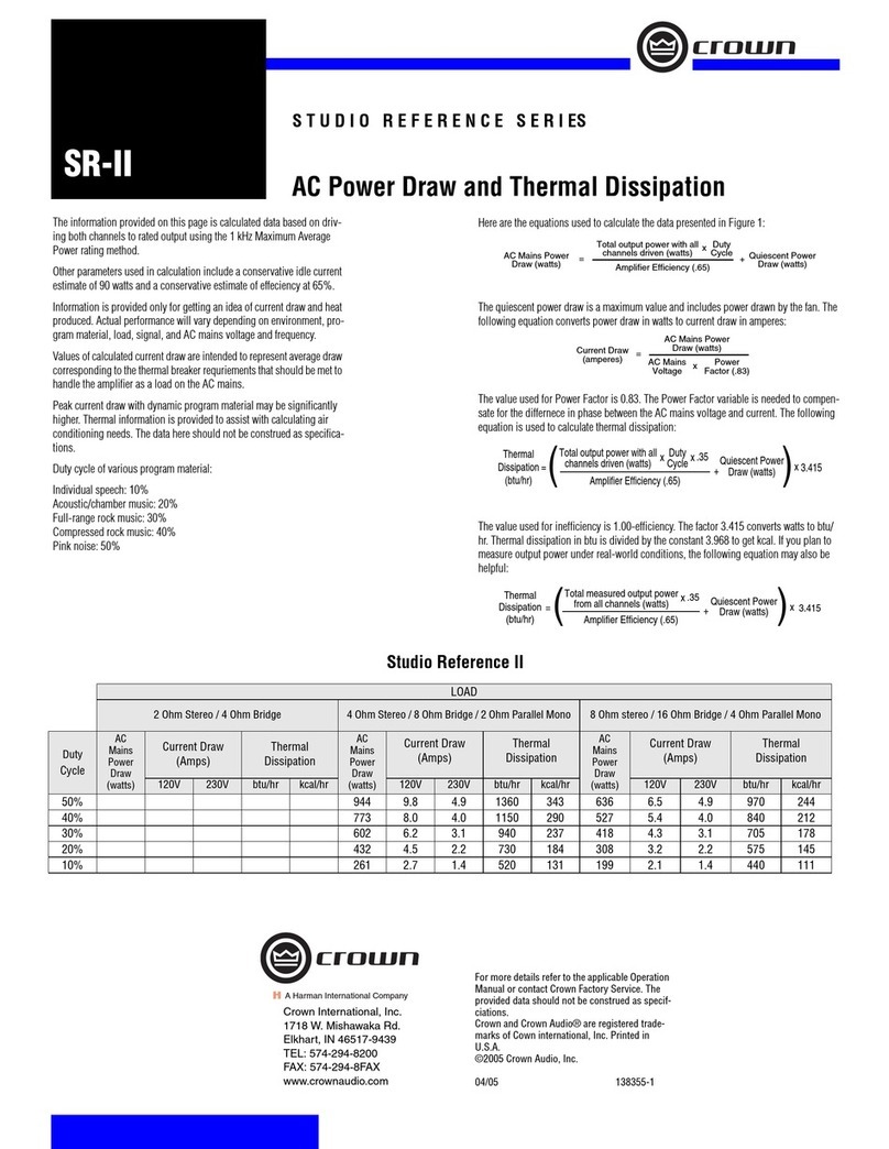
These 50W, 100W, 150W and 180W
amplifiers may be used on the mains or bat-
tery for safety duties.
They are built in 19” half format; two units
can be assembled side-by-side, taking up
less space.
These units have the tone correctors and
light indicators required for optimal use.
•Output powers (RMS)
50 W - 100 W - 150 W - 180 W
(
in accordance with model)
•Distortion ....................................................< 1%
• Bandwidth (-3dB)
65 - 20 000 Hz .................... for the AR1050,
AR1100 and AR1150
75 - 20 000 Hz ......................for the AR1180
• Tone control
Bass ..........................................±8 dB at 100 Hz
Treble ........................................±8 dB at 10 kHz
•Signal/noise ratio (unweighted)......
≥80dB
• Input................ 0dB balanced 10kΩ (transfo)
•Outputs
Line ................0 dB balanced parallel at input
Low impédance ............................................4 Ω
High impedance 70 V 100V
AR 1050 100 Ω 200 Ω
AR 1100 50 Ω 100 Ω
AR 1150 33 Ω 66 Ω
AR 1180 27 Ω 55 Ω
•Power supply
mains............................ 230V+terre 50/60Hz
battery .................................................... 20-32V
•Consumption (
in accordance with model)
mains ..................110 / 200 / 300 / 460 VA
battery .................................. 3 / 5,5 / 8 / 10 A
• Dimensions ....212 x 325 x 135 mm (Fig. I)
•Weight ..............................6 / 8 / 8,8 / 9,3 kg
•Rack 19" mounting with set handles AZ 8
(Fig. II).
•Options
AZ 1330 : amplifier fault detection board
for AR 1050, AR 1100 and AR 1150.
AZ 1310 : amplifier fault detection board
for AR 1180.
AZ 8 -
Handle set for rack mounting
•Feature
Cooled by fan with thermostat.
A
AR
R
1
10
05
50
0
A
AR
R
1
11
10
00
0
A
AR
R
1
11
15
50
0
A
AR
R
1
11
18
80
0
AMPLIFICATEURS
50W-100W-150W-180W
50W-100W-150W-180W
AMPLIFIERS
Ce document n'est pas contractuel; toute modification pouvant intervenir sans préavis / This document is not legally binding, we reserve the right to modify descriptions and specifications without notice.
Code 595 795 - 12/2003
AZ 8 - Jeu de poignées
Handle set AZ 8
Fig. I
Fig. II
Ces amplificateurs de 50W, 100W, 150W
et 180W sont utilisables sur secteur ou sur
batterie pour les applications de sécurité.
Leurs dimensions, demi-format 19", per-
mettent d'assembler deux appareils côte à
côte pour un encombrement réduit.
Ces appareils sont dotés de correcteurs de
tonalité et de témoins lumineux néces-
saires à une utilisation optimale.
•Puissances de sortie (RMS)
50 W - 100 W - 150 W - 180 W
(
suivant modèle)
•Distorsion ....................................................< 1%
• Bande passante (-3dB)
65 - 20 000 Hz ................ pour les AR1050,
AR1100 et AR1150
75 - 20 000 Hz ........................pour l’AR1180
• Correction de tonalité
Graves........................................±8 dB à 100 Hz
Aigus ..........................................±8 dB à 10 kHz
•Rapport signal/bruit (non pondéré)
≥80dB
• Entrée ........ 0dB symétrique 10kΩ (transfo)
•Sorties
Ligne ....0 dB symétrique parallèle à l’entrée
Basse impédance..........................................4 Ω
Haute impédance 70 V 100V
AR 1050 100 Ω 200 Ω
AR 1100 50 Ω 100 Ω
AR 1150 33 Ω 66 Ω
AR 1180 27 Ω 55 Ω
•Alimentation
secteur.......................... 230V+terre 50/60Hz
batterie .................................................... 20-32V
•Consommation (
suivant modèle)
sur secteur ........110 / 200 / 300 / 460 VA
sur batterie.......................... 3 / 5,5 / 8 / 10 A
• Dimensions ....212 x 325 x 135 mm (Fig. I)
•Poids ..................................6 / 8 / 8,8 / 9,3 kg
•Montage en rack 19" avec le jeu de poi-
gnées AZ 8 (Fig. II).
•Options
AZ 1330 : carte de surveillance d’amplifica-
teurs AR 1050, AR 1100 et AR 1150.
AZ 1310 : carte de surveillance d’amplifica-
teur AR 1180.
AZ 8 - Jeu de poignées 3U
•Particularité
Refroidissement par ventilation thermostatée.
480, avenue de Paris • 82042 MONTAUBAN CEDEX • FRANCE
Tél : 33 (0)8 92 70 20 82* (*0,34 €la minute TTC) • Fax : 33 (0)5 63 03 08 26 • http://www.bouyer.com
I - DESCRIPTION I - DESCRIPTION
II - CARACTÉRISTIQUES TECHNIQUES II - TECHNICAL SPECIFICATIONS
Front face (Fig. III)
1 “On/Off” switch
2 ON indicator lamp
3 Modulation indicator lamp
4 Crest limitation indicator light
5 Overheat indicator lamp
6 Volume control
7 Bass tone control
8 Treble tone control
9 Ventilation grille
Rear face (Fig. II)
10 Mains plug 230V with ground
11 Mains supply fuse (5 x 20)
12 Power output terminals
13 Information default terminals (optional)
14 + and - battery power supply terminals
15 Balanced XLR output, 0 dBm (parallel at input)
16 Balanced XLR input, 0 dBm
17 Ventilation grille
ATTENTION
The unit is neither water - nor splash proof.
Before any manipulation, disconnect the mains cable.
After manipulation, put back the cover and check that the
ground wire (yellow + green) is connected properly.
• Mains Connection
The unit is supplied for use with 230V with ground.
•24 V Battery Connection
Connect the + and - terminals to the battery by means of a
≥2mm2 cross-section lead.
The battery fuse 6x35 is on the main circuit at the back of the
cabinet.
•Modulation source connection
The modulation source is connected on the female XLR socket
(balanced input on the transformer). An identical output signal is
available on the male XLR plug.
• Loudspeaker connection
Connect the appropriate loudspeaker output on the amplifier to
the loudspeaker line.
A l’avant (Fig. III)
1 Interrupteur “Marche / Arrêt”
2 Témoin lumineux de mise sous tension
3 Témoin lumineux de modulation
4 Témoin lumineux d’écrêtage
5 Témoin lumineux de température excessive
6 Réglage de volume
7 Réglage de tonalité grave
8 Réglage de tonalité aiguë
9 Grille de ventilation
A l’arrière (Fig. IV)
10 Prise secteur 230V avec terre
11 Fusible (5 x 20) secteur
12 Borniers sorties de puissance
13 Bornes d’information de défaut (option)
14 Bornes + et - d’alimentation batterie
15 Sortie XLR symétrique 0 dBm (parrallèle à l'entrée)
16 Entrée XLR symétrique 0 dBm
17 Grille de ventilation
ATTENTION :
L’appareil ne doit pas être exposé aux chutes d’eau et
aux éclaboussures.
Avant toute intervention, déconnecter le câble secteur.
Après l’intervention, refermer l’appareil et vérifier que le
fil de terre (jaune et vert) soit bien connecté.
• Branchement secteur
L’appareil est livré pour un fonctionnement en 230V avec terre.
•Branchement batterie 24 V
Raccorder les bornes + et - à la batterie avec des conducteurs de
section ≥ 2 mm2.
Le fusible batterie 6x35 est situé sur la carte principale à l’arrière de
l’appareil.
• Branchement source de modulation
Raccorder la source de modulation à la prise XLR femelle (entrée
symétrique sur transfo). Un signal de sortie identique est disponible
sur la prise XLR mâle.
• Branchement des haut-parleurs
Raccorder la sortie HP appropriée de l'amplificateur à la ligne des
haut-parleurs.
2AR 1050 - AR 1100 - AR 1150 - AR1180
Fig. III
4
Fig. IV
!!
III - PRESENTATION III - PRESENTATION
IV - INSTALLATION IV - INSTALLATION
Joining the two AR together and loosen the
front and rear stops 1 (Fig.V) which are
fastened by Pozidriv screws.
Slide the 4 coupling pieces 2 .
AZ 2030 as shown in the drawing (Fig.VI).
(2 pieces in front and 2 in the rear).
Tighten the screws.
Once assembled, two devices can be moun-
ted in a 19” rack. Remove the stops and the
lateral covers.
Replace the lateral covers with the handles
supplied in kit AZ 8 (Fig. VII and Fig. VIII).
After connection, but before switching on,
adjust the volume to "0". Switch the device
ON using the ON/OFF switch 1 (Fig. III).
The ON indicator LED 2 lights up. Adjust
the volume and the tone to the desired
level.
Maximum power is obtained using a 0 dB
input signal.
For use with grounded equipment,
switch SW1 on board should be
opened to avoid hum due to
ground loops.
Adjustment of the tone control can
be limited by closing switches
SW6 and SW7 on the main board.
In case of failure :
Check the status of the fuses and
replace them if needed by fuses
with the same caracteristics as
those indicated on the product.
Wait until the product has cooled
off, to be sure that the failure is
not caused by the thermal relay.
If not, unit must be returned to
the factory, or repaired by an
official service station.
Accoler deux appareils AR et desserrer les
butées avant et arrière 1 (Fig. V) fixées par
des vis cruciformes.
Glisser les 4 pièces de jumelage 2
AZ2030 suivant le croquis (Fig. VI).
(2 pièces à l'avant et 2 à l'arrière).
Serrer les vis.
Pour le montage en rack 19"(après avoir
assemblé deux appareils), démonter les
butées et les caches latéraux. Remplacer les
caches latéraux par les poignées fournies
dans le kit AZ8 (Fig. VII et Fig. VIII).
Après branchement et avant la mise sous
tension, tourner le volume en position "0".
Mettre l'appareil sous tension à l'aide de l'in-
terrupteur 1 (Fig. III). Le témoin 2 de
mise sous tension s'allume. Ajuster le niveau
sonore et la tonalité en fonction de l'utilisa-
tion désirée.
La puissance maximale est obtenue par un
signal d'entrée de 0 dB.
En cas d'utilisations avec d'autres
appareils reliés à la terre, il est
conseillé d'ouvrir l'épingle SW1
située sur la carte pour éviter des
ronflements dûs aux boucles de
masse.
L'inhibition des réglages de tonali-
té est possible en fermant les
épingles SW6 et SW7 de la carte
principale.
En cas de panne :
Vérifier l’état des fusibles et les
remplacer si besoin par des
fusibles de mêmes caractéris-
tiques tel qu’indiqué sur l’appa-
reil.
Attendre que l’appareil refroidis-
se pour s’assurer que la panne
n’est pas due à la protection ther-
mique.
Sinon retourner l’appareil à
l’usine, ou faire appel à un dépan-
neur professionnel.
AR 1050 - AR 1100 - AR 1150 - AR1180 3
Fig. VIII
Fig. VII
Fig. VI
Fig. V
! !
!•
•
•
!•
•
•
V- ASSEMBLAGE 2 APPAREILS V- ASSEMBLY OF 2 DEVICES
VI - MONTAGE EN RACK VI - RACK MOUNTING
VII - UTILISATION VII - USE
VIII - MAINTENANCE VIII - MAINTENANCE

This manual suits for next models

3

Other Bouyer Amplifier manuals

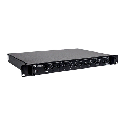
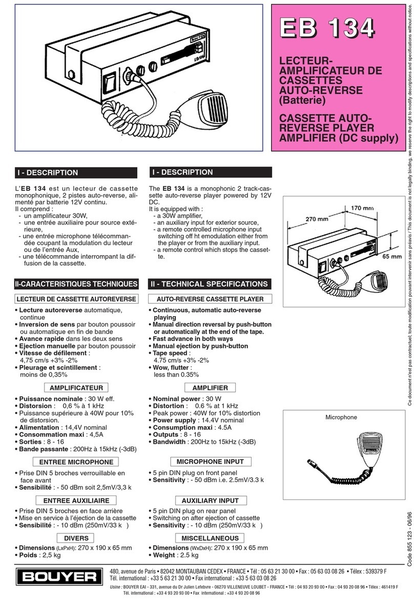
Bouyer AP 3804 User manual

Bouyer

Bouyer AP 3804 User manual

Bouyer AM-2015-PACK User manual

Bouyer

Bouyer AM-2015-PACK User manual

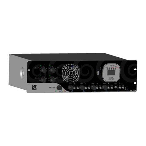
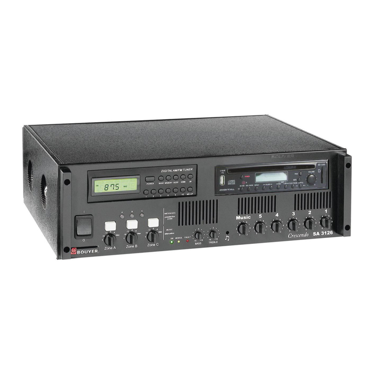
Bouyer SA-3126 Series User manual

Bouyer

Bouyer SA-3126 Series User manual

Bouyer AS-4000 Series User manual

Bouyer

Bouyer AS-4000 Series User manual

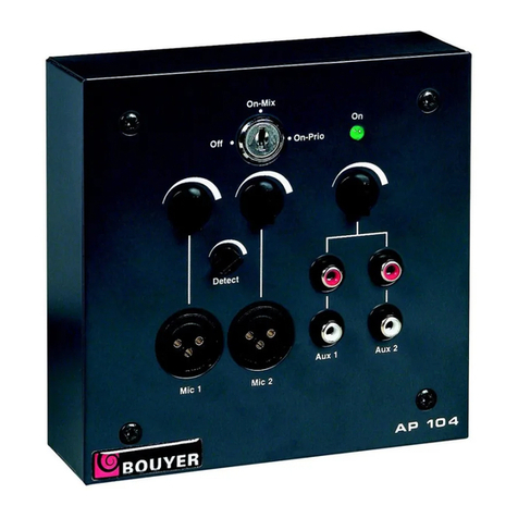
Bouyer AP-104 User manual

Bouyer

Bouyer AP-104 User manual

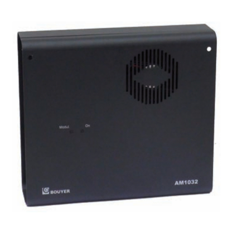
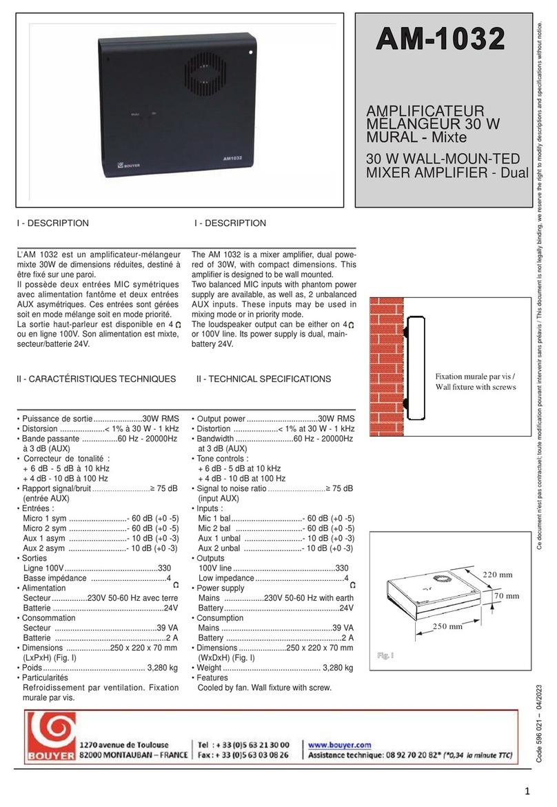
Bouyer AM 1032 I User manual

Bouyer

Bouyer AM 1032 I User manual

Bouyer IL 100 User manual

Bouyer

Bouyer IL 100 User manual

Bouyer EB 134 User manual

Bouyer

Bouyer EB 134 User manual

Bouyer GE 3067 User manual

Bouyer

Bouyer GE 3067 User manual

Bouyer SA-1127 User manual

Bouyer

Bouyer SA-1127 User manual

Bouyer AM-2015 User manual

Bouyer

Bouyer AM-2015 User manual

Bouyer AR 1402 User manual

Bouyer

Bouyer AR 1402 User manual

Bouyer EXCELLENCE Series User manual

Bouyer

Bouyer EXCELLENCE Series User manual

Bouyer EXCELLENCE PR 1406 User manual

Bouyer

Bouyer EXCELLENCE PR 1406 User manual

Bouyer SA 3126 User manual

Bouyer

Bouyer SA 3126 User manual

Bouyer AD1-1075 User manual

Bouyer

Bouyer AD1-1075 User manual

Bouyer AS 3066 User manual

Bouyer

Bouyer AS 3066 User manual

Bouyer GE 3267 User manual

Bouyer

Bouyer GE 3267 User manual

Bouyer AM-1032 User manual

Bouyer

Bouyer AM-1032 User manual

Bouyer Crescendo SA 3126 Instruction manual

Bouyer

Bouyer Crescendo SA 3126 Instruction manual

Popular Amplifier manuals by other brands

FONESTAR MAX-360Z instruction manual

FONESTAR

FONESTAR MAX-360Z instruction manual

BLUENOTE DEMIDOFF owner's manual

BLUENOTE

BLUENOTE DEMIDOFF owner's manual

Bugera 1990 user manual

Bugera

Bugera 1990 user manual

Marshall Amplification 2061X user manual

Marshall Amplification

Marshall Amplification 2061X user manual

Fishman AGP-2 Template

Fishman

Fishman AGP-2 Template

AR 300T2G8 Series Operating and service manual

AR

AR 300T2G8 Series Operating and service manual

Carver Professional PM-300 owner's manual

Carver Professional

Carver Professional PM-300 owner's manual

Richwood Performer 65 owner's manual

Richwood

Richwood Performer 65 owner's manual

Sony TA-N731 Service manual

Sony

Sony TA-N731 Service manual

Demeter Amplification HBP-1 H series user guide

Demeter Amplification

Demeter Amplification HBP-1 H series user guide

MUSETEC AUDIO MH-SA001 user manual

MUSETEC AUDIO

MUSETEC AUDIO MH-SA001 user manual

Studiomaster Professional PA Series owner's manual

Studiomaster Professional

Studiomaster Professional PA Series owner's manual

NuWaves NuPower 05E05A user manual

NuWaves

NuWaves NuPower 05E05A user manual

Carver PM-300 owner's manual

Carver

Carver PM-300 owner's manual

Omega OMNI-AMP IV Series user guide

Omega

Omega OMNI-AMP IV Series user guide

PYLE Audio PT610 user manual

PYLE Audio

PYLE Audio PT610 user manual

Omnitronic B-600 user manual

Omnitronic

Omnitronic B-600 user manual

Crest Audio VS450 Specifications

Crest Audio

Crest Audio VS450 Specifications

manuals.online logo
manuals.online logoBrands
  • About & Mission
  • Contact us
  • Privacy Policy
  • Terms and Conditions

Copyright 2025 Manuals.Online. All Rights Reserved.