Euroalpi Pasubio User manual

Use and maintenance
manual for pellet
stove

2
English User Manual
Dear Customer
We thank you and we are honoured that you have chosen one of our products. Please read this manual
carefully; in it you will find all the information and helpful advice for using the product with the maximum
safety and efficiency.
The manual supplied with the stove should be guarded and in case of loss or destruction, it is necessary to
request a copy from your dealer or from the company, specifying the serial number of the stove, on the
back side.
Summary
1 Misconduct
Pag. 2
2 Safety
Pag. 3
3 Warnings
Pag. 3
4 Regulations and declaration of conformity
Pag. 4
5 Warranty
Pag. 4
6 Responsibility
Pag. 7
7 Installation
Pag. 7
8 Technical specifications
Pag. 13
9 First ignition
Pag. 14
10 Modes of operation
Pag. 16
11 The menu
12 Alarms
13 Maintenance, cleaning, testing the stove
14 Spare parts
15 Wiring diagram
16 Duct
17 Notes
Pag. 21
Pag. 30
Pag. 34
Pag. 38
Pag. 40
Pag. 41
Pag. 43
1 Misconduct
In this section, we will list some small rules to follow for the correct working of the stove and safety.
All the operations not considered in the manual and not authorized by a technician
recommended by the company, must be considered dangerous. Otherwise, the ZF
company does not assume any responsibility both civil and criminal.
Strictly forbidden
-Not observing the use and maintenance manual.
-Using the stove for any other use not provided (exclusively for heating).
-Touching the surfaces of the stove when it is hot.
-The use of the stove by children or unable people without assistance.
-The use of the stove by people who don’t know the minimal safety regulations.
-The manual introduction of pellet into the brazier.
-Operating the stove with broken or not compliant parts (irregular flue, splintered glass, non-
original spare parts, etc.)
-In case of firing failure, restarting the stove without first having emptied the brazier.
-In case of firing failure, restarting the stove without first having waited 10-15 minutes.
-Throwing away unburnt pellets (still burning), after having cleaned the brazier.
-Introducing pellets recycled from the combustion chamber or brazier.
-Neglecting stove cleaning (glass and flue included).
-Cleaning the stove with water (water could filter inside of the stove and damage its electric parts).

3
-Igniting the stove in case of any component failure.
-Exposing oneself for a long time directly to the hot air of the stove.
-Exposing animals, plants and any flammable thing to the air of the stove.
-Placing any kind of object on the stove.
-Drying clothes or objects on the stove
-Tamper with the parameters of the stove.
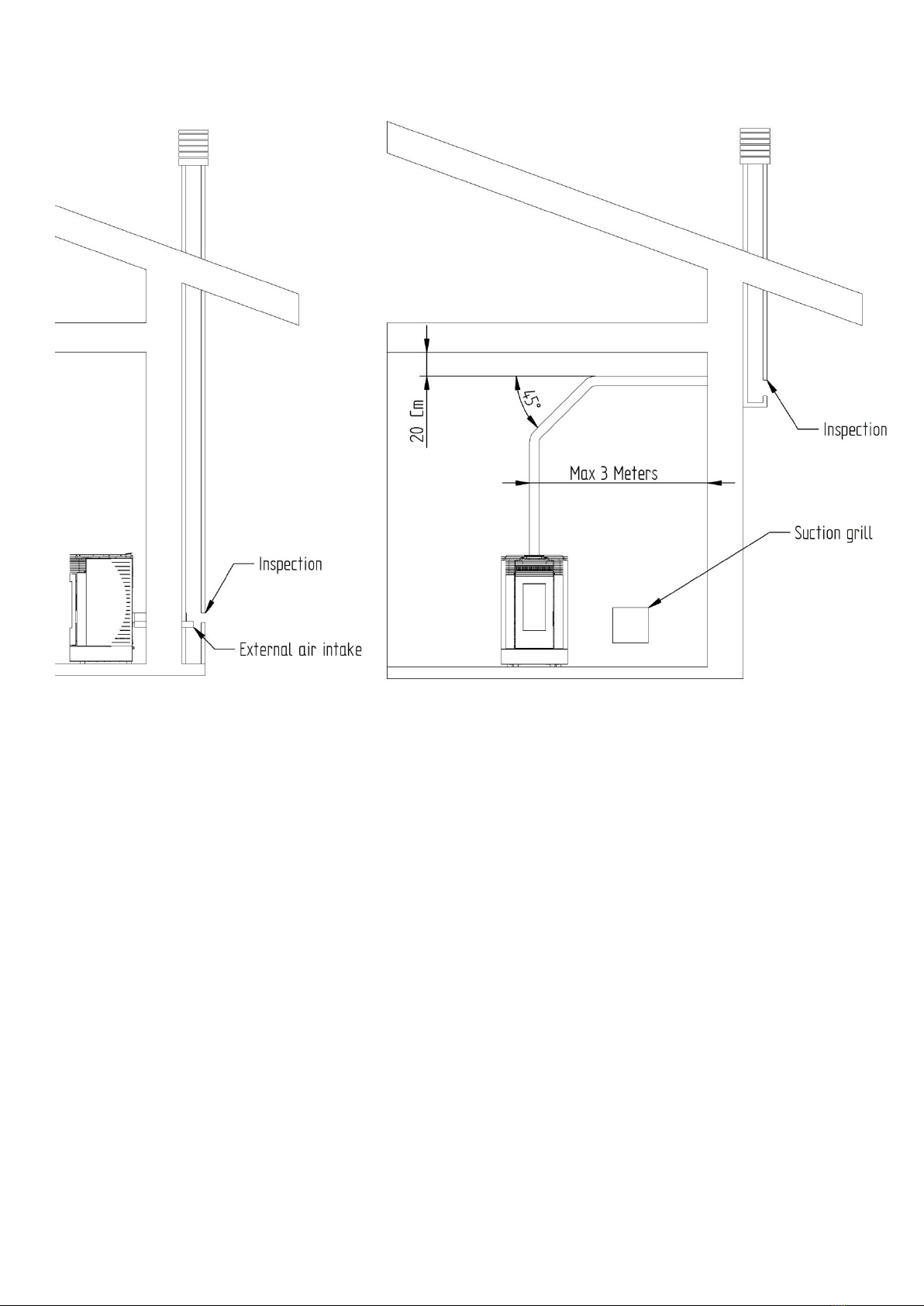
-Installing the stove in not specific conditions and rooms.
-Using the device as an incinerator and fuels other than those recommended.
-Using a quality of pellet that doesn’t meet the regulations DIN 51731.
-Not executing the maintenance operations provided.
-Staying within 2 meters from the stove in case of firing failure for the first 10 minutes.
-Operating the stove with the door open.
-Touching the stove with bare hands.
-It is forbidden to turn on more devices simultaneously in the same room; installing multiple
devices with forced ventilation can cause the malfunction of the stove.
2 Safety
-The installation of the stove, the flue, electrical connections, checking its operation, should always
be carried out by authorized and qualified personnel.
-Install the stove in accordance with the regulations of the local area, region or state.
-For the proper use of the stove and electronic parts, you must follow the instructions in the user's
manual.
-Use only pellets with a diameter of 6 mm regulations DIN 51731.
-Incorrect installation or poor maintenance (not in compliance with the provisions in this booklet of
"Use and Maintenance") can cause damage to people and things. In this case, the company ZF is
released from any civil or criminal responsibility.
-Before performing any operation, the user must have read and understood all the contents of this
manual of "Use and Maintenance".
-Tampering and misuse of the stove can be dangerous for the user’s safety. In these cases, the ZF
Company declines any civil or criminal responsibility, resulting from damages to people and things.
-When the stove is in operation, most of the surfaces are very hot (glass, handles, tubes and shells);
you must then use the appropriate protections for the contact.
-It is forbidden to operate the stove with broken glass, the door opened or any part broken (fans,
motors, etc..).
-Before carrying out any cleaning or maintenance, disconnect the stove from the power supply with
the power switch; after that, remove the cable on the back of the stove, check the cooling of the
entire internal and external structure, and of the ash in the combustion chamber.
-In case of fire in the flue: switch off the stove, disconnect the power supply and never open the
door of the stove. Call the authorities (fire department).
-The stove must be electrically powered by a system of earthing conductor, as provided by law
73/23 and 93/68 EEC.
3 Warnings
-Turn the stove off in case of breakdown or malfunctioning.
-Never introduce pellets manually into the brazier.
-Make sure the brazier is empty before turning on the stove (even in case of previous firing failure).

4
-Every initiative or operation not considered in this manual must be considered dangerous. In this
case, the ZF company does not assume any responsibility both civil and criminal.
-Do not clean the interior and exterior parts of the stove with water.
-Do not expose plants, animals, things and people to the hot air of the stove for too long.
-Install the stove in locations suitable for the prevention of fire and already prearranged for safety.
-The storage of the stove and the covering of all its parts (even those in ceramic) must take place in
rooms without humidity and far from bad weather.
-Do not set the body of the stove directly on wood or flammable floors, in these cases always put
an insulating material between the stove and the floor.
-The pellet stove is not an apparatus for cooking or heating up foods and drinks.
-Carry out all operations in maximum safety.
-Do not place any object on the stove.
-Do not dry any cloth, object, or being (animals, plants, etc.) on the stove.
4 Regulations and declaration of conformity
The ZF company states that the stove complies with the following directives and regulations for the CE
marking European Directive:
2014/30/UE (EMCD Directive) and following amendments.
2014/35/UE (Directive on the safety of electrical equipment LVD) and following amendments.
2011/65/UE RoHS
European Standards: EN 55014-1; EN 55014-2; EN 61000-3-2; EN 61000-3-3; EN 60335-1;
EN 60335-2-102; EN 62233; EN 50581; EN 14785.
For the installation and the use of the stove all the local and national and all European standards must be
met.
5 Warranty
Warranty conditions
ZF s.r.l. located in Dino Fochesato Street n.1 Meledo of Sarego (VI) guarantees its products for 2 years
from the date of purchase, for manufacturing or material defects. This warranty falls if the flaw of
conformity is not reported within 2 months from the date of its detection.
ZF s.r.l. limits its responsibility to the supply of the stove, which has to be installed in accordance with the
state-of-the-art, following the instructions contained in the manual supplied with the product and in
accordance with the laws in force. The installation must be carried out by qualified staff and under the
responsibility of the person who designates him, who will assume responsibility for the final installation
and the consequent good operation of the installed product. ZF s.r.l. declines any responsibility in case of
non-observance of these precautions. The installer will have to release a Declaration of conformity of
the installation in accordance with the state-of-the-art, in accordance with the laws in force.
Examples of installation technicians:
-Authorized Service Centers technicians
-Technicians and companies associated Anfus (National Association Stove Fitting) (Italy)
-Technicians adherent to national school training plans Fuspa (Italy)
-Your trusted technicians (qualified thermotechnics)

5
Territorial expansion of the warranty: Italian territory
Validity of the warranty
The warranty is valid on condition that:
-The buyer sends within 8 days from the date of purchase the coupon in his possession completed
in its entirety. The date of purchase must be validated by the possession of a valid tax record
released by the seller
-The device is installed by qualified staff, in accordance with the laws in force and the instructions
contained in the provided manual
-The device is used as illustrated in the provided manual
-The guarantee certificate has been filled in and signed by the costumer and validated by the dealer
-Presence of the document certifying warranty, filled in and accompanied with the tax record
released by the dealer, to show to the ZF s.r.l. Technical Service Center in case of assistance
Revocation of the warranty
The warranty is not valid in the following cases:
-The above warranty terms have not been observed
-The installation is not carried out in full obedience of the laws in force and the instructions
contained in the provided manual
-Non-maintenance or wrong maintenance of the product by the customer
-Presence of electrical and/or hydraulic systems not in accordance with the laws in force
-Damages caused by weather conditions, chemical, electrochemical agents, improper use of the
product, natural calamities, modifications or tampering with the product, flaws of the electrical
system or of the flue, use of non-original spare parts, sudden change in voltage or overloaded
power supply or other causes not attributable to the product
-The combustion of materials not in accordance with the type and the quality indicated in the use
and maintenance manual supplied with the stove.
-Damages caused during transport. We invite you to properly check your goods at the time of
receipt. In case of anomalies, inform immediately the dealer and report everything in the transport
document and in the copy which will remain in the possession of the carrier.

6
The warranty covers possible spare parts and the necessary labour for their substitution (with the
exception of products installed outside the Italian territory).
In case of products installed outside the Italian territory only the Italian warranty is valid, therefore the
local importers or distributors are not obliged to recognize warranty interventions on what has not been
purchased through them. In these cases, the spare parts will be sent directly from our headquarter and the
replacement and maintenance costs will be debited to the customer by the area technicians.
The ZF s.r.l. company is not responsible for possible damages caused, directly or indirectly, to people,
things, animals due to a total or partial failure to comply with the rules contained in the use and
maintenance manual supplied with the stove.
Limited warranty
Electric and electronic components, fans, motors and motherboard are not included in the warranty. The
warranty covers these components for 12 months from the date of purchase.
Warranty exclusion
All components of the stove likely to wear out are excluded from the warranty and they are:
Gaskets Ceramic/tempered glass Upholstery and grills
Varnished details Chromate/gilded Satinized
Majolica Handles Electric cables
Vermiculite Refractory material Brazier
-Chromatic variations, crackles and slight dimensional differences of the parts in majolica are not
contestable as they are all physical features of the materials not attributable to the manufacturing
process
-The details of the installation for the production of sanitary water not furnished by ZF s.r.l. (for
water products)
-Finally, all interventions carried out by qualified technicians aimed at the adjustment and setting of
the product due to the type of combustible used or the typology of installation requested by the
customer are excluded from the warranty
-In case of replacement of faulty components under warranty, any warranty extension won’t be
provided. Any type of reimbursement for the rest period of the machine won’t be provided
-The warranty is valid only for the buyer and cannot be transferred to a third-party
Warranty interventions
The request for intervention must be submitted to the dealer within 2(two) months from the detection of
the damage; the warranty intervention, according to the law, provides for the reparation of the product
without any charge to the customer.

7
6 Responsibility
The ZF company refuses any responsibility whether civil or criminal, for any damage that may directly or
indirectly result from non-compliance, partial or total, of the instructions contained in the booklet "manual
of use and maintenance".
The ZF company refuses any responsibility whether civil or criminal, arising from the incorrect or improper
use of the stove by the end-user, refuses any civil or criminal responsibility in the case of unauthorized
repairs and the use of non-original spare parts, moreover, it is not liable for damages to the stove due to
transport and does not recognize compensation for forced stopping of the stove.
The manufacturer disclaims any responsibility whether civil or criminal direct or indirect due to:
-Non-compliance with the instructions contained in the booklet
-Inadequate maintenance and cleaning
-Installation errors
-Non-compliance with safety regulations
-Installation by unqualified and untrained personnel
-Installation not in accordance with the regulations in force in the country
-Use of non-original spare parts
-Exceptional events (weather, power surges, strange places of installation)
-The ZF s.r.l. does not recognize any compensation for direct or indirect damages caused or
depending on the product.
In the above cases the warranty falls.
7 Installation
Recommendations for the installer
The installation of the stove must be carried out by qualified technicians who have to install the stove in
accordance with the European laws and the laws in force in the place, Region or State.
The stove must be electrically powered by a system in accordance with the regulation 72/23 and 93/68
CEE on the power grid.
The stove must be sized according to the space in which it is installed.
The stove must be positioned vertically.
The stove mustn’t be installed in bedrooms, bathrooms or where there is another heating system without
a self-sufficient air flow (fireplace, etc.).

8
Spaces and distances
It is essential to check the space where the stove will operate for an optimal operation.
-The volume of the house or the working space mustn’t be smaller than 40m³.
-There has to be a permanent opening of airflow to the outside of the place of the installation,
minimum 800 cm², not obstruable and protected with a permanent grill, or the stove has to be
connected to the outside by an air intake tube (as shown below), do not exceed 80 cm in length
with 2 curves maximum.
-The air can be taken by the rooms contiguous to the room where the stove has been installed on
condition that there are air intakes, not located in the bedroom, bathroom or where there are
flammable materials.
-If the stove is installed in a room with
wooden or flammable floor, you must
protect the floor by using (in addition
to the anti-vibration feet provided)
also an insulating slab, protruding at
least 20 cm on the side and 40 cm on
the front.
-In the space where the stove is placed, it is compulsory the presence of a suitable fumes
evacuation system
-It is not compulsory to connect the air intake tube of the stove directly outside (see picture) but it
is recommended for a better efficiency (energy-saving). In any case, it is necessary to ensure at
least 50 m³/h of air. Grill 800 cm².
-The electrical system must be in accordance with the law; check the efficiency of the earthing
circuit. The supply line must be of an appropriate section to the power of the device.
-When you place the stove in a room you must
check that the walls are not flammable and that
flammable materials such as curtains,
wallpaper, etc. have not been applied on the
walls. You must place the stove at a distance
not less than 20 cm laterally and not less than
10 cm at the back. If there is an internal flue it’s
advisable to keep a distance of 10 cm between
the flue and the wall.
-Do not place flammable materials at a distance
less than 1 meter from the stove.
-We also recommend to keep out of the thermal
radiation area, anyway at a distance of at least
1 m from the warming block, all types of
combustible or flammable materials such as:
trusses, wooden fittings, curtains, flammable
liquids.

9
Flue
The flue of a pellet stove is a very important component because it affects the correct working of the
stove.
The flue must be needed only for the stove and cannot be shared with other devices; you can’t make fixed
or movable openings to connect other air adduction pipes and pipes for plant-engineering use.
The flue must be provided with a chamber for the gathering of solid materials and possible
condensations, placed under the entrance of the flue outlet duct, so that you can easily open it and
inspect it from an air-tight small door.
The installer has to make sure that the opening do not cross
flammable materials, or in the absence of alternative
solutions, he has to use an insulating protection on the pipe
(with wall junctions with a diameter of 13 cm at least,
insulating the pipe with insulating materials 1,5-5 cm thick,
with a suitable thermal conductivity), even though it passes
near flammable materials (minimum distance 200 mm).
As for the assembly of the pipes you must always use pipes
and junctions with hermetically sealed gaskets.
It’s important that the curvature of 90° provides for a T
junction with inspection; it is advisable to use curves of 45°.
Using nets or filters at the extremity of the flue or any
extremity which could turn into a nest is forbidden. Use only
extremity in accordance with the regulation.
The horizontal segments must have a minimum inclination of
3% upward.
As for the connection of the flue, the horizontal segment
must be minimum and you mustn’t exceed 3 meters, the
number of direction changes, including that as a result of the
use of the T element, mustn’t be bigger than 4, never exceed
6 m of pipes, use curves of 45° and obey the regulations UNI 10683, using pipes in accordance with the
law.
Examples of connections with isolated and non-isolated external pipes
Connections that include the use of pipes not larger than 20 cm in diameter, which must have at the base
an inspection system and a forced draught minimum 10 Pa. The internal section must be uniform,
preferably circular; the sides of the pipe must be smooth as much as possible and without narrowings; the
curves must be regular and without discontinuities; the pipes mustn’t be subjected to deviations from the
axis higher than 45°.
It is compulsory the installation of a windproof roof in accordance with the regulations. The T inspection,
placed at the base, can also be placed inside the house (better if external).

10
NB: This system always guarantees the fumes evacuation, also in case of non-electric tension
Connection with multiple junctions
Connection that is exclusively done in cases of particular disadvantages in positioning. In this case, the
horizontal section must have a minimum slope of 3% upwards and must not exceed 3 meters, the vertical
section that goes from the stove to the second curve must be at least 1.5 meters long. The T inspection, at
the base, can also be applied inside the house (preferably external). If there is a fireplace, it must have a
preferably circular internal section; the square or rectangular sections must have rounded corners with a
radius of at least 20mm, the rectangular sections, with a maximum ratio of 1.5 between the sides, must
have a constant internal section, free and independent; at the base there must be an inspection hole.
Always verify a minimum forced draught of 10Pa and follow the regulation UNI 10683.
NB: In case of obstruction of the pipe, due to damages, or birds’ nest, the stove will stop (see the alarms
section) and it will be necessary to clean or repair the pipe, and ventilate the room as quickly as possible,
otherwise, it will saturate with smoke.
NB:The cleaning of the pipe should be done annually.

11
Chimney pot
The chimney pot must meet the following requirements:
-Have the section and the internal form equivalent to that of the flue.
-Have a useful exit section not less than twice that of the flue.
-Be constructed to prevent the penetration of rain, snow, foreign bodies in the flue so that in case
of winds in any direction and inclination, the discharge of the combustion products is assured
(windproof chimney pot).
-The chimney pot must be positioned to guarantee an adequate dispersion and dilution of the
combustion products and, however, outside the reflux area. This area has different sizes and
shapes, depending on the angle of slope of the roof, so it is necessary to adopt the minimum
heights (see figure).
-The chimney pot must be windproof and exceed the height of the peak or, where it is not possible,
comply with the values indicated in the table.
-Any buildings or other obstacles, which exceed the height of the chimney pot, must not be close
to the same chimney pot.

12
Draught
The draught of the stove is essential to have good performances in specific adverse weather conditions
(rain, fog, snow, altitude, cold, wind), and it is conditioned by the position of the flue. Adverse weather
conditions that affect negatively the draught are various; particularly burdensome is the wind, which can
be: ascending, horizontal, descending.
-Ascending wind: increases the depression and consequently the draught.
-Horizontal wind: it increases the depression, only in the case of a right installation in the direction
of the wind.
-Descending wind: decreases the depression and consequently the draught.
The flue, if placed in the upwind side, increases the overpressure and consequently, in the opposite
situation, increases the depression, decreasing the draught.
To overcome these drawbacks, the installer must act directly on the stove, modifying the parameter to
adjust the speed of fume extraction and verify all safeties. This operation is particularly delicate, it must
always be carried out by authorized personnel. The ZF company declines any liability, whether civil or
criminal, for missed control by the installer of all safeties.
Distances and positioning
Roof inclination
Distance between the peak
and the chimney
Minimum height of the chimney
(Measured from the block)
β
A
H
15°
<1,85
50 centimeters beyond the top
>1,85
1 meter from the roof
30°
<1,5
50 centimeters beyond the top
>1,5
1,3 meters from the roof
45°
<1,3
50 centimeters beyond the top
>1,3
2 meters from the roof
60°
<1,2
50 centimeters beyond the top
>1,2
2,6 meters from the roof

13
Characteristics
Model PASUBIO
Thermal power introduced (at rated power)
6,82 kW
Thermal power introduced (at reduced power)
3,43 kW
Nominal thermal power (at rated power)
6,20 kW
Reduced thermal power (at reduced power)
3,17 kW
Yield (at rated power)
90,89 %
Yield (reduced power)
92,49 %
Fumes temperature (at rated power)
104,6 °C
Fumes temperature (at reduced power)
68,4 °C
Carbon dioxide (at rated power)
6,89 %
Carbon dioxide (at reduced power)
4,95 %
CO at 13% O₂ (at rated power)
140,8 mg/m³
CO at 13% O₂ (at reduced power)
580,2 mg/m³
Fumes speed (rated power)
6,9 g/s
Fumes speed (reduced power)
4,7 g/s
Min. and Max. draft
10 Pa –12 Pa
Pellets tank capacity
17 Kg
Pellet consumption (at rated power)
1,4 Kg/h
Pellet consumption (at reduced power)
0,7 Kg/h
Pellets autonomy (at rated power)
12 h
Pellets autonomy (at reduced power)
24 h
Air inlet diameter
Ø 50 mm
Fumes outlet diameter
Ø 80 mm
Voltage and frequency of power supply
230V~ 50/60Hz
Electrical power absorbed Min - Max
150 W -380 W
Fuel
Wood
Kind of fuel
Pellet
Size of the fuel
Ø 6 mm - Length 30 mm
Weight of the stove
Kg 103,5
Note: The data reported in the table may vary substantially depending on the pellets used (calorific value). To
calculate the power of the stove to be installed, depending on the needs, take into account that 1 kW = 9.2 m²
(with h = 2.70 m.).
8 Technical specifications

14
The pellet
To obtain the maximum performance, the ZF company suggests to use pellets of the quality prescribed by
the regulations DIN51731.
Length: 30mm
Diameter: 6mm
Calorific value: 4.9 ÷ 5.3 kWh / kg
Humidity max: 6%
The pellets must be stored in a dry place away from heat sources. The ZF company assumes no
responsibility for malfunction due to the use of poor quality pellets.
9 First ignition
Warning
The first ignition will have to be carried out by a qualified technician who will have to check:
-That all the regulations mentioned above and the current regulations in the place of installation
have been applied.
-The correct installation: of the stove, the flue, the chimney pot.
-That there is no risk of damage to the stove or to the room of installation. In case of problems, the
ZF company assumes no liability both civil and criminal.
First steps
Check that there are no objects on the stove (manual included) and proceed as follows:
-Fill the hopper with pellets, opening the upper door and closing it again, making sure that no
foreign body is in the hopper. Take off the cover of the hopper only during its charging.
-Check that the brazier is well positioned in its place.
-Check that the door is hermetically closed.
-Supply power, put the general switch ON (it is placed in the back down side); the control display
will light up.
-During the first few times, there may be cases of unpleasant smells due to the presence of greases
and oils on the components used during the production phase. Ventilate the space and avoid
staying there for long periods until the smells disappear.
9.1 User interface
The console unity permits to talk to the controller by simply pressing some buttons. A display and other
LED indicators inform the operator that the stove is working. In programming mode are displayed the
different parameters that can be modified by pressing some buttons.

15
9.2 Console description
In the figure below it is described the use of the standard console that can be supplied to be fitted
horizontally.
9.3 Function of the buttons
Button
Description
Mode
Action
1
Temperature
Increment
WORK/OFF
It increments the room temperature value
PROGRAMMING
It modifies/increments the selected parameter
2
Temperature
Decrement
WORK/OFF
Decrement of the room temperature value
PROGRAMMING
It modifies/decrements the selected parameter
value
3
SET/MENU
-
Enter the menu
SET/MENU
Enter the next submenu level
PROGRAMMING
It sets the selected value and passes to the next
entry
4
ON/OFF
WORK
Pressed for 2 seconds, it turns on and off the
stove
PROGRAMMING
It passes to the next level of the menu and all
modifications carried out are memorized
BLOCK
It unblocks and turns off the stove
5
Power
Decrement
WORK/OFF
It reduces the value of the stove power
PROGRAMMING
It passes to the next submenu entry and all
modifications carried out are saved
MENU
It passes to the next submenu entry
6
Power
Increment
WORK/OFF
It increases the value of the stove power
PROGRAMMING
It passes to the previous submenu entry and all
modifications carried out are saved
MENU
It passes to the previous submenu entry

16
9.4 Meaning of the LED
Led
Meaning when turn on
Icon
CHRONO
Chrono enabled
ALARM
Stove on the alert
IGNITION
Ignition on
AUGER
Auger in motion
FUMES ASPIRATOR
Fumes aspirator on
EXCHANGER-PUMP
Exchanger \ pump on
NOT USED
Not used
9.5 Display
10 MODES OF OPERATION
Premise
The installer must make the first start by taking precautions, and must ensure that the safeties are working
properly (pressure switch, hopper temperature protection etc...). Any anomalies with the installation can
not be attributed directly to the ZF company. The installer must carry out any other try he deems
necessary and verify the operation of the buttons on the console.
10.1 Igniting the stove
Once the installation of the stove and the compulsory verification of the safeties are over, the operation
phase begins. To power the stove, simply connect the cable to the electrical outlet, press the power switch
located on the back of the stove at the bottom, moving from position 0to position 1as shown in (Figure
1).
Figure 1
Display
Function
Conditions
Visualization
DISPLAY
Power
state
parameter
name
OFF
OFF+ROOM TEMPERATURE+WORK POWER+HOUR
ON
ON+ ROOM TEMPERATURE+WORK POWER+HOUR
LOAD
FED PELLET+ ROOM TEMPERATURE+WORK POWER+HOUR
WORK
ROOM TEMPERATURE+WORK POWER+HOUR
PROGRAMMATION
SELECTED PARAMETER

17
Before switching on the stove, the display appears as shown in Figure 2.
Figure 2
To turn on the stove, press on P4 for a few seconds. The successful ignition is indicated in the display with
the message "START" as in (Figure 3). This phase lasts for a time given by the parameter PR01. Under these
conditions, the stove will go in the state of preheating, the ignition turns on (shown by the ignition LED)
and so does the smoke extractor. Malfunctions during the ignition phase are shown on the display and the
stove goes into an alarm state.
(Refer to chapter 9).
Figure 3
10.2 Pellet loading
After about 1 minute, the pellet loading phase begins, the message "LOAD PELLET" passes on the display.
In a first phase the auger provides to load the pellets in the brazier for a time given by the parameter
PR40 (auger LED on), the speed of the fumes is defined by parameter PR42 and the ignition is always on
(ignition LED on). In the second phase, after the time of the parameter PR40 has passed, the auger turns
off (auger LED off) for a time given by the parameter PR41, while the speed of the fumes and the ignition
remain in the previous state. If the stove does not turn on after this phase, the auger turns on for a period
given by the parameter PR04, the fumes speed is given by the parameter PR16 and the ignition is on.
(Figure 4).
Figure 4
14:15
22.5°c P-2
OFF
14:15
22.5°c P-2
START
14:15
22.5°c P-2
LOAD
Pellet

18
10.3 Fire Present
After the fumes temperature has reached and overcome the value contained in the parameter PR13, the
system goes into power mode displaying "FLAME LIGHT" on the display. In this phase, it is checked that
the temperature remains stable for a predefined time given by parameter PR02. The fumes speed is given
by the parameter PR17, the auger will turn on for a time given by the parameter PR05 (auger LED on
intermittent) and the ignition is switched off (ignition LED off). (Figure 5)Any anomalies will stop the board
and this will report the error state. (Refer to chapter 9).
Figure 5
10.4 Stove on working mode
After the fumes temperature has reached and overcome the value contained in PR13 and maintained it for
at least a time PR02, the stove goes into working mode which is the normal operating. The display will
show the word "WORK". The power can be set by holding down the button P5 and P6 and the room
temperature can be set by pressing the button P1 and P2. (Figure 6). If the fumes temperature reaches the
threshold set by parameter
PR15, the air exchanger fan
lights on. (Led exchanger on).
Figure 6
During this phase, after a time given by the parameter PR03, the stove carries out a cleaning of the
brazier. The message " CLEANING FIRE-POT " will pass on the display, the auger is turned on (auger LED
on) with a speed given by the parameter PR09, the smoke extractor speed given by parameter PR08.
(Figure 6a) Once the given time by the parameter PR12 has passed, the stove backs in working state.
Figure 6a
14:15
22.5°c P-2
Flame
light
14:15
22.5°c P-2
WORK
14:15
22.5°c P-2
CLEANING
FIRE - POT

19
10.5 Changing the heating power set
During the normal operation of the stove (Work), you can change the heat power output by using the
buttons P5 (Decrease) and P6 (Increase). The power level set is shown on the display. (Figure 7) To exit
from the menu wait 5 seconds without performing any operation on the keyboard, or press P3.
Figure 7
10.6 Changing the room temperature
To change the room temperature it is enough to act on the button P1. The display shows the set room
temperature (SET temperature). Thus acting on the buttons P1 (increase) and P2 (decrease) it is possible to
change the value. After about 5 seconds the value is saved and the display returns to the normal mode, or
press P3 to exit. (Figure 8).
Figure 8
10.7 The room temperature reaches the set temperature
(SET temperature)
When the room temperature has reached the set value, the heating power of the stove is automatically
decreased to the minimum value. Under these conditions, the display shows the message
"MODULAT-". (Figure 9). If the room temperature decreases below the set one (Set temperature) the
stove goes back to "Work" mode and to the power previously set (Set power).
Figure 9
03
set
power
30.0°C
Set room
temp
14:15
22.5°c P-2
work
Modulat-

20
10.8 Stand-by
If enabled in the menu, standby function allows to turn off the stove once the conditions explained below
are respected. It is enabled if, at a given time by the parameter PR44, the room temperature is higher than
the set temperature (Set environment) plus the parameter PR43. The display shows " STANDBY " and the
minutes left. (Figure 10).
Figure 10
At the end of the time given by the parameter PR44, the display shows the message "WAIT COOLING". In
this state, the stove has turned off the auger (auger LED off), the exchanger switches off when it reaches
the threshold given by the parameter PR15 and the LED ON \ OFF flashes. (Figure 10a).
Figure 10a
When the fumes temperature reaches the threshold given by the parameter PR13, the stove goes into
stand-by mode and "WAIT COOLING-" passes on the display. The auger is off (auger LED off), the
exchanger is off (exchanger LED off), as well as the smoke extractor. (Figure 10b).
Figure 10b
If the room temperature drops below the set temperature (Set environment) minus the threshold given by
the parameter PR43, the stove will switch on again.
Standby
WAIT
COOLING
WAIT
COOLING -
Table of contents
Other Euroalpi Pellet Stove manuals
Popular Pellet Stove manuals by other brands

Piazzetta
Piazzetta P963 THERMO Instructions for installation, use and maintenance

MCZ
MCZ EGO-STAR AIR installation guide

IronStrike
IronStrike Bella Installation and operation manual

Harman Stove Company
Harman Stove Company P68 owner's manual

PRITY
PRITY PLS Technical description and operating instructions

HearthStove
HearthStove Manchester 8330 owner's manual

Ariterm
Ariterm MYSINGE Installation and operating instructions

SPI
SPI EasyFire Series Replacement Instruction

England's Stove Works
England's Stove Works 25-EP Installation & operation manual

Enviro
Enviro Alliance EF3 owner's manual

Enviro
Enviro Alliance EF3 owner's manual

Ravelli
Ravelli o-ring user manual