Euroheat Edition D N1087 User manual

©EUROHEAT DISTRIBUTORS (H.B.S) LTD. March 2006 Technical Guide IN1087 Edition C
1
The Flue Guide
3.
%
7
Conventional Flue Systems
IN1087 Edition D

©EUROHEAT DISTRIBUTORS (H.B.S) LTD. March 2006 Technical Guide IN1087 Edition C
2
Cannot
be
assumed to work
The installer is responsible under the health and safety at work act 1974 vi the caustic nature
of re cement and the possibility of disturbing asbestos and other materials such as ceramic in
existing installations and to suggest appropriate protection to be given to the person (s) carrying
out the installation. The complete installation must be carried out with due reference to the British
Standards, Codes of Practice and Building Regulations relevant to the fuel type being installed,
and the manufacturers installation instructions.
This document is a General Installation Guide only. It does not replace the installation instructions
or building regulations. No installation should be undertaken unless the installer is suitably
qualied.
Flue Size comparison / volume increase
4” or 100 mm to 5” or 125 mm is an increase of 62.4 %
4” or 100 mm to 6” or 150 mm is an increase of 134 %
5” or 125 mm to 6” or 150 mm is an increase of 44 %
5” or 125 mm to 7” or 175 mm is an increase of 228 %
6” or 150 mm to 7” or 175 mm is an increase of 38.5 %
Pipe Diameter / Cross sectional area
4” or 100 mm = 11.7 sq. ” or 7854 sq. mm
5” or 125 mm = 19.0 sq. “ or 12271 sq. mm
6” or 150 mm = 27.4 sq. “ or 17671 sq. mm
7” or 175 mm = 38.5 sq. ” or 24825 sq. mm
Euroheat have provided this document for general help and assistance
with your ue requirements. The documents aim is to assist with the correct
installation with our product range of Wood, Multifuel, Oil and Gas Stoves.
However much of the enclosed information can be of assistance with other
professionally designed stoves.
It is more than a coincidence that flue is ananagram of fuel; both need to be correct.
Use full documents and those referred to in this document
Building Regulations
Approved document J April 2002
Approved Document J: 2002 Edition:
Guidance and Supplementary Information on the UK
Implementation of European
Standards for Chimneys and Flues October 2004.
Approved Document L1A 6th April 2006
Approved Document L1B 6th April 2006
Approved Document L2A 6th April 2006
Approved Document L2B 6th April 2006
Approved Document F Means of Ventilation 2006

©EUROHEAT DISTRIBUTORS (H.B.S) LTD. March 2006 Technical Guide IN1087 Edition C
3
Flue
Flue liner
Thermal insulation
Outer wall
Chimney section
Cladding
Chimney fitting
Connecting flue pipe
Heating appliance
Chimney
(Multi-wall)
CHIMNEY TERMINOLOGY.
Not identified in
the Standard
(As defined in the European
Standard EN 1443)

©EUROHEAT DISTRIBUTORS (H.B.S) LTD. March 2006 Technical Guide IN1087 Edition C
4
Conventional Gas Flue Installation
ABC
ATwin wall insulation internal to property
B. Top ue routed externally
C. Rear ue routed externally

©EUROHEAT DISTRIBUTORS (H.B.S) LTD. March 2006 Technical Guide IN1087 Edition C
5
Chimney Construction

©EUROHEAT DISTRIBUTORS (H.B.S) LTD. March 2006 Technical Guide IN1087 Edition C
3
Why is a ue necessary?
Combustion is a chemical reaction which gives off heat when the chemical components of the
fuel are broken down and combined with oxygen. The oxygen needed for this reaction to occur is
obtained from the air brought into the stove, and the ue allows both the products of combustion and
the air which is depleted of oxygen to be passed directly into the atmosphere and diluted. The ue
performs this task, but the speed at which it carries away these gases regulates the supply of fresh
air to the stove. That this is controlled within dened parameters is vital to any stove achieving high
combustion efciency because insufcient air will not allow the complete oxidisation of the fuel and
any air passing through the stove unnecessarily only serves to cool the stove.
What is ue draught?
Because the ue plays such an important part in the efciency and controllability of all naturally
aspirated fuel burning appliances, its performance is quantied under the term “ue draught”. This is
the measurement of either the speed at which the gases travel in the ue or the difference in pressure
between the incoming air and the outgoing gases.
What causes ue draught?
Flue draught is caused by two very different effects the ue is subjected to. Firstly the ow induced
by the difference in temperature between the gases within the ue and that of the air outside the
ue, and secondly the ow of wind around the property and the ue termination. Both of these are
often misunderstood, so we have attempted to explain their causes and effects in detail.
Flue draught without wind.
After being involved in the combustion process the gases making up the products
of combustion are heated and have expanded to become less dense than the
surrounding air, and so rise because they weigh less than an equal volume of the
surrounding air. Why they should rise is not complicated and can be illustrated by
releasing water (a dense substance) over a bucket containing air (a less dense
substance), where the water will fall to the bottom of the bucket, forcing the air
upwards. Whilst air and water have very differing densities, cold and hot gases
behave in the same way, and it is the weight of cold air which forces the hot air up
the ue. With the greater the differences in temperatures, the greater differences
in densities and the faster the gases will be driven up.
From this we can establish several important facts:-
1. A hot ue does not “draw” air into a stove, it is the
differences of densities that motivate the lighter gases
upwards.
2. The greater the temperature difference between
the gases within the ue and the surrounding air, the
greater the difference in densities and the greater the
motivation.
3. The taller the ue, the greater the weight of the
equivalent volume of denser air, the greater the
motivation.

©EUROHEAT DISTRIBUTORS (H.B.S) LTD. March 2006 Technical Guide IN1087 Edition C
4
A ue system for an open re has an enormous margin for design error because it receives so much
of the heat generated by the re, and the re is not expected to be controlled beyond the rate at which
it is refueled. The efciency of a stove is achieved because less of the heat generated by the re is
lost to the ue, and that the ue design allows consistent control of the re. These impose design
constraints which become progressively more restrictive as the stove’s efciency increases. With
less motivation the ue route taken must provide the smoothest path possible to retain as much of
the heat in the gases as possible.
If we look at the ue’s prime function, which is to remove the harmful products of combustion, we nd
that even the chemicals themselves become more difcult to deal with at reduced ue temperatures.
One of the more important chemicals formed by the combustion process is oxygen dihydrate, a
chemical better known as water. The ability of the gases to “absorb” water is dependent on their
temperature and when the gases are “saturated”, the water will begin to condense out as the
temperature falls. The point at which the water will be shed by the gases is known as the “dew
point”, but unlike the picturesque dew covered image of dawn, this condensate will combine with
all the nasty acidic chemicals in the ue gases as it runs down the ue wall. Evidence of this can be
seen on the walls of old properties where this acidic water has been absorbed by the masonry ue
and has eaten away the lime mortar. This will be worse where the ue has been for a range or oven
which take out more heat from the re. If the re has been primarily fueled with wood, the creosote
and resinous tars may even reach the internal plaster not only staining them but posing a re risk
because these tars are combustible. The ue needs to maintain the gases above the dew point
and this is achieved by making the ue as smooth as possible to reduce any friction between the
wall and the gases which will allow the smallest possible diameter to be used and so minimize the
surface area through which heat may be lost. A ue constructed from stainless steel satises all the
requirements because it is smooth, impervious to the chemicals, its low mass allows rapid warming
and it can be easily cleaned. Flexible metal ue liners should be installed in one unbroken length.
Other than the sealing at the top and bottom the void between the ue and the chimney should be
left empty except in circumstances where the void is deamed to be large.
Existing chimneys should have a stainless steel liner tted. If the void between the liner and masonry
is large it may be lled with vermiculite to provide insulation it will then reach its operating temperature
more rapidly. Where no chimney exists, a twin walled, interlocking stainless steel system should be
used. The walls are separated by an insulating material.
An appliance produces a known quantity
of hot gases, capable of generating a
flue draught, whatever the flue size, if
its temperature difference is maintained.
All ues allow heat loss and reduce the
potentialavailable.Toreduceheatlostfrom
the ue the most basic design consideration
is to ensure its surface area is kept to a
minimum, by tting the smallest diameter
recommended for the appliance.
©EUROHEAT DISTRIBUTORS (H.B.S) LTD. March 2006 Technical Guide IN1087 Edition C
5
No flue operates in isolation, but is a
component part of a complete system,
with the stove and house affecting its
performance. Whilst we normally think of
ues only when the stove is operating, the
same rules of heat induced ow in the ue
apply when the stove is not lit. If the house
is hotter than the outside air, the ue will
perform as if the stove was lit, with the
warm air from the house travelling up the
ue. However, on those odd days when it
suddenly becomes warm and the outside
temperature is higher than the temperature
in the house, the ue will operate in reverse
with the possibility of sooty smells being introduced into the house, and will make it very difcult to light
the stove. This reversed air ow may provide sufcient air for the stove to ignite and burn poorly, but
the products of combustion will spill into the house. Because none of the heat from the re is passing
into the ue it will not warm to correct the air ow until the heat from the re has warmed the stove
to allow conduction of this heat to the ue. If reverse ow is noticed before lighting the stove a fan
heater should be directed into the stove through the open door for several minutes before attempting
to light the stove. (see page 28, Spring and Autumn syndrome)
X
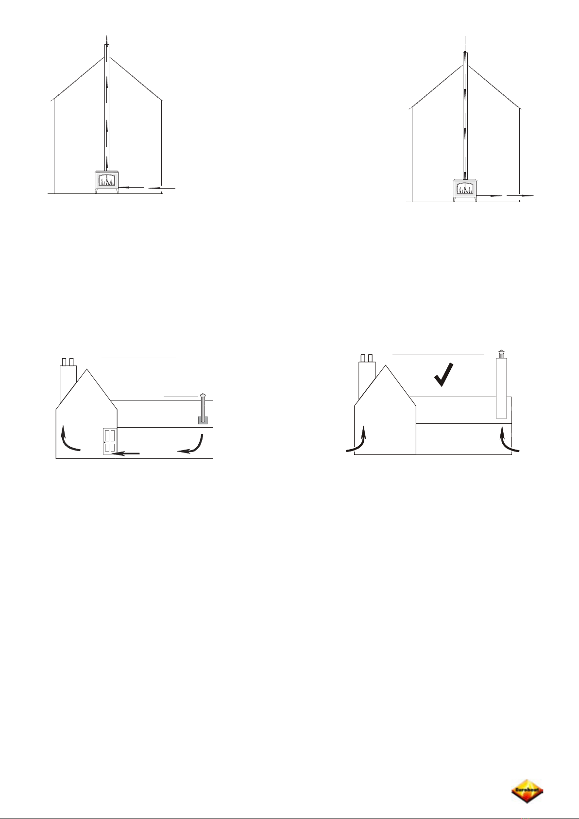
A more complex example of reversed ow in ues is caused by multiple ues and differences in
ue heights and again the effects will become evident even before any re is lit. All the ues will
tend to aspirate as in the previous example, but with increasing numbers of ues the throughput of
air increases resulting in considerable loss of heat from the house. Reducing these heat losses, by
improving the sealing of doors and windows has led to the loss of numerous small ventilation areas
and unless provision has been made for specic ventilation to each ue the air ow in each ue will
depend upon the balance of temperature and height of them and will inevitably result in the coldest
or shortest ue acting as the incoming air supply. This will not only cause smells and difculty in
lighting the reverse owing ue, this imbalance has the potential of becoming dangerous. A typical
example would be where an open re is in use and a stove is installed with a shorter ue. Because
an open re allows so much of its heat to escape up the ue the ue operates at a very much higher
temperature than that of a stove’s ue resulting in an imbalance of draft motivation. If this imbalance
is increased by a difference in height it is quite possible for the shorter ue to stall or even reverse
ow when operating, allowing the oxygen depleted air from the stove to spill into the house.
Adequate permanent ventilation must always be provided for each re in the house, whether open
res or stoves.
Ventilation must allow for any air extraction systems such as kitchen or shower room fans.
The heights of all ue terminals should be equal.

©EUROHEAT DISTRIBUTORS (H.B.S) LTD. March 2006 Technical Guide IN1087 Edition C
6
What effect does wind have?
Because wind is inconsistent its effects pose an ever changing challenge for its control. We have
already established that the ue cannot be looked at in isolation from the house and this will become
even more evident as wind is taken into consideration. Regulations demand that permanent air
venting must be provided for fuel burning appliances, but whilst their specied openings will operate
as intended on a windless day, unless thought is given to their placement it is possible that an air
vent may become worthless or even dangerous on a windy day.
If we look at the terminals we carefully balanced to perform similarly, we will nd that when the wind
blows in one direction, air will be pushed into one air vent increasing the air pressure into the stove
whilst the other vent will be situated in an area of reduced pressure and may even allow air to be
drawn out from the room. This problem can be minimized by siting air vents away from obvious wind
traps and by tting several vents, whose combined area is to the requirements, in different locations
so that wind will affect each one differently, simultaneously.
The opening of windows and doors, even in light winds, may also affect the air ow, and may make
lighting the stove difcult if the opening is down wind. If the stove is seen to be affected by wind at
certain times it is worth investigating if extraction fans being turned on is a cause or that people having
a discrete cigarette at an open window are unwittingly causing the problem.
If an air stream passes across the ue terminal it induces ue draught, which if we are to maintain
a quantiable air supply to our stove, it needs to be controlled. If wind caused an air stream which
was consistent in all but speed, the effect it has on the terminal could be cancelled out by placing
a system of bafes or vanes over the terminal. However, wind is not simply a stream of air, it is a
constantly changing mixture of speed, direction and pressure, and controlling the effect it has on the
ue draught begins with ensuring that the terminal is not sited where this combination is too complex
to deal with.
Allobstructionstothewindwillchangeitsqualitiesand the mostobviousobstructionwillbe thehouse
itself. The impressive chimney structures which are found on many old houses were built to put the
terminals well above the roof and the air pressures and turbulence caused by the roof. Changes in
house designs, and the mistaken belief that tall chimneys were simply an extravagance has resulted
in this clearance being reduced to a minimum and in some houses to the inadequate. This erroneous
trend may well have been caused by the use of simplistic drawings of wind passing over a house. In
the following illustrations wind is shown blowing towards the house from both directions.
It would seem logical to assume the terminal in the left hand illustration would have wind blowing in
the upwards direction with a resultant high draught. The wind in the right hand drawing blowing down
the terminal to reduce the ue draught. These types of drawings only show wind direction and make
no allowances for pressure, but putting an obstruction in the face of wind causes high pressure to
form at the wind side of the obstruction and low pressure at the other side. Now if pressures are
taken into account the situations become more complex.
©EUROHEAT DISTRIBUTORS (H.B.S) LTD. March 2006 Technical Guide IN1087 Edition C
7
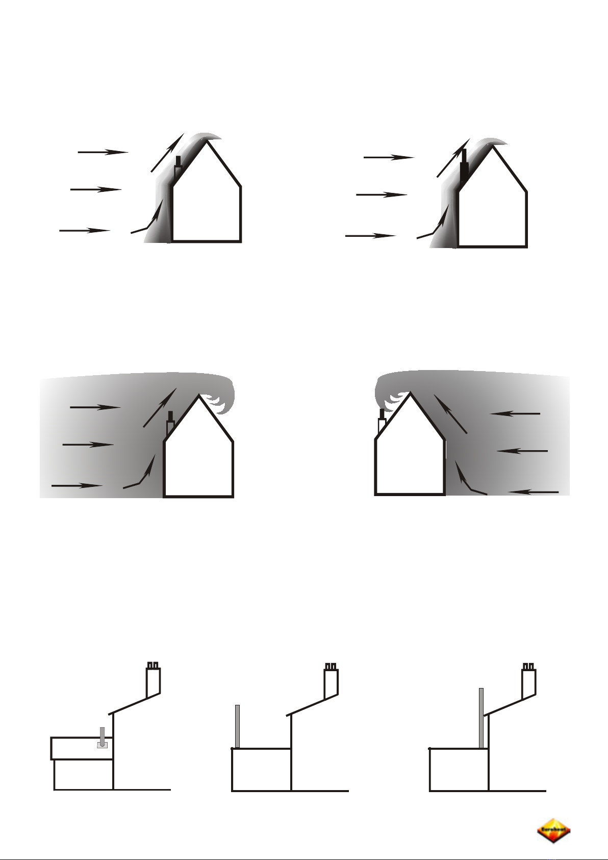
The following drawings remain simplistic but with the addition of even simplistic representations of
pressure the original expectations have changed. In the left hand drawing the high pressure may well
be high enough to negate the effects of wind speed and even stall the ue. The effect of pressure
will become greater with the steepening of the roof angle and the lower the terminal. The theory of
raising the terminal a little to clear the depth of the high pressure supposes this to exist only as a
shallow skin over the roof, which is not true.
Abuilding has more in common with a sail than the wind slipping properties of an aircraft and not only
is the depth of high pressure far deeper than has been presupposed, the turbulence and pockets of
varying pressures are more unpredictable.Again the following drawings are simplistic but they begin
to illustrate the complexity of wind and pressures. The left hand drawing shows that simply raising the
terminal a metre or so will have little effect and the right hand drawing shows the random conditions
the terminal will be subjected to.
Perhaps the best illustration of air ow around a building is a windy day with ne snow falling. Several
minutes spent watching the snow’s direction changes will not teach you the ability to predict air ow
over and around a terminal but it will teach you that it is very much more complex and less predictable
than drawings like these can show.
It should be obvious by now that the next illustrations are of ues which are fundamentally wrong for
many reasons.
X
X
X

©EUROHEAT DISTRIBUTORS (H.B.S) LTD. March 2006 Technical Guide IN1087 Edition C
8
Even by putting the terminal in what should be an ideal position there is no certainty that consistent
resultscanbeobtainedbecausethewindrarelyarrivesatthepropertyunaffectedbyobstructionsalong
its path or indeed by the very contours of the ground itself. Before looking for potential problems with
the property that may be caused by obstructions nearby a far wider area should be looked at, taking
time to look at other chimneys. If every old house nearby has what seems to be a disproportionately
tall chimney it will be because of difcult wind patterns in the area and not because every builder liked
working at high altitudes. Ask about smoking res and try to relate the problem with wind direction
and features which may cause turbulence over an area rather than just the property itself.
Having looked at the surrounding landscape, the obstructions nearby will need to be noted. Not only
will the terrain cause problems in this illustration, the houses will be affected by each other and the
effects will be completely different with each change of wind direction.
The effect of trees in particular should not be underestimated because they may have no effect for
many years, but begin to affect the terminal with increasing intensity as they grow. They will also
have different effects with or without leaves and when laden with snow.
There is rarely a simple and totally satisfactory solution to overcoming the problem of the effects of
wind turbulence.
TIME

©EUROHEAT DISTRIBUTORS (H.B.S) LTD. March 2006 Technical Guide IN1087 Edition C
9
Methods of controlling the ue.
If there is to be any hope of controlling the ue it must be installed to put the terminal in the best
possible position, it must have sufcient height and it must maintain temperature. So returning to the
situation where the ue needs to operate on a still day we have had to ensure sufcient height and
a minimum heat loss to enable the ue to give sufcient negative pressure in the stove on a mild
day, it will cause too much negative pressure on a cold day, when the density differences between
the atmosphere and the ue gases are greater. The device for sorting out this little problem is called
a “barometric damper” or “ue stabilizer”, which can be tted either in the ue or the ue way of the
stove. It consists of a hinged ap with an adjustable balance weight which is adjusted to allow the ap
to open when the negative pressure within the ue is too high. This immediately limits the pressure
and by spilling cold air into the ue the resultant ow of gases are cooled and the ability for the ue
to generate pressure is reduced.
This device will also open whenever wind induces too much ow in the ue and so would seem to
have solved all potential problems caused by an over enthusiastic ue, however, the more astute
reader may have already spotted the weakness of this device, which is that it operates at only one
setting. For a stove capable of burning fuel at different rates, the negative pressure induced by the
ue will need to match the air supply to the fuel supply. An increase in ue temperature, as the fuel
rate is increased, will achieve this, but if the damper blade has to be set to limit the negative pressure
at any point below the stoves maximum rate the ue will probably be unable to achieve pressure
required for the maximum rate. If the ue induces too much negative pressure in the stove throughout
the entire range of ring rates it is possible to t a plate to throttle the ue but because the throttling
effect increases with the increasing ow within the ue it will only be an effective cure over a limited
range and it will not control the effects of wind. The reality of these devices are that they are set to
open at a mythical “ideal” with the hope that good fortune takes care of everything else. One stove
manufacturer has developed a variable stabilizer which magnetically adjusts the pressure at which
theblade opensto the required pressure at all burningrates, whatever the weather.Astrongly biased
opinionofthisdevicepreventsmewritingfurtherdetailsofthisamazingstabilizer,butbecausesetting
it up correctly is simple, none is needed.
Now we move to the other end of the ue and look at the terminal itself. While you were outside
watching the snow swirling and travelling in any direction other than those drawn in “wind passing
terminal” drawings you may have noticed that the simple chimney pot, which has been used for
hundreds of years, is nally being replaced by more scientic terminals. With so many diverse shapes
andsizesyouwouldbeforgivenforwonderingwhichsciencetheywerebasedon,andindeedmanyof
uswonder. Inanagewheretechnologywithcomputermodellingandallthenecessarytestequipment
have narrowed the discrepancies between the designs of solutions to problems it is interesting that
cowls would seem to be the exception. But perhaps even more interesting is that each cowl design
will have a number of people who will regard it to be a perfect solution and a similar number of people
who regard it as worse than useless.

©EUROHEAT DISTRIBUTORS (H.B.S) LTD. March 2006 Technical Guide IN1087 Edition C
10
In its simplest form the chimney cowl is nothing more than a rain cap. These were unnecessary in a
brick chimney because most of the rain falling down was absorbed by the bricks and the absorbed
water evaporated out whenever the re was lit. With appliances like stoves so little heat is wasted
that we have to line and insulate the ue which gives a direct passage to the stove. The moment
you t anything above the ue terminal is the moment everything becomes horribly more complex
than you ever imagined. The following drawings show that tting a rain cap on a chimney pot will
almost reverse the effect of vertically rising or falling wind. I accept that these winds are not normal
but provide the extremes of possibility and between them are angles of wind that make the words
“almost reverse” important.
Almost all winds moving in an upward direction will be caught by the cowl to form an area of high
pressure above the ue, but wind moving in a downward direction will also be able to blow into the
ue as its angle decreases. When this angle is reached the effect will be a sudden change and all
sudden changes are difcult to control. Changing the diameter of the cowl and its height above the
ue in an attempt to stop this will make the ue worse in upward wind directions or let the rain in.
Beforedismissingthesimpleraincapcowlitmustberememberedthatwehavegivennoconsideration
toeffectsthehouseitselfwillhaveonthewinddirectionandthosetogetherwithotherpressurefactors
might make a cowl like this of certain proportions the perfect terminal.
It is this unknown element which makes the choice of cowl so difcult. A cowl which gives the solution
to one problem ue may exacerbate the problems of a ue with identical problems in a similar house
in a different location, but cowls can be put into very loose categories as to their purpose. Whilst
almostall cowls claim to be “anti down draught”otherspurportto do more.Of themoresimpleshapes
are those illustrated next.
The left hand snorkel is mounted above the chimney pot on a bearing allowing it to be rotated by
windblowingatits vane and causingtheopeningtofacedown wind consistently.Whilstsolvingsome
problems, by maximizing the effect of wind, the resultant difference in ue draught between wind
and windless conditions is too great for any stove and draught control system to cope with. The cowl
on the right is often seen as an enormous terracotta affair on low or badly sited old chimneys and
works by ensuring that all air passing results in the air ow causing air to be drawn out of the ue.
This cowl manages to cope with almost every wind direction and a modern, light weight version is
available, but as with the snorkel it tends to amplify the differences in the ue’s performance making
it difcult to control the draught within the parameters necessary for stoves.

©EUROHEAT DISTRIBUTORS (H.B.S) LTD. March 2006 Technical Guide IN1087 Edition C
11
There are many variations using the basic principles of these cowls with varying degrees of success
but all are capable of increasing the ue draught beyond the limitation of our control for stoves because
they were originally designed for open res.
Another approach to a cowl which should give less variation in wind generated ue draught is to cover
the mouth of the ue with a box vented with slots, louvers or course mesh in an attempt to slow the
wind speed passing the mouth of the ue. These may slow the air speed but because the box will
need to be large enough to spread the area of the ue diameter it creates its own negative pressure
on the downwind side while the upwind side, if the slots are doing anything at all will be limiting the
high pressure entering. The net result will be a slower air ow but an increase in the negative pressure
over the ue mouth caused by the box obstructing the air ow and creating a negative pressure
pocket on the downwind side.
The effects of winds blowing in anything but a horizontal direction will depend on many things but
the angle of the air stream may be such that it is not prevented from acting directly onto the ue
mouth. Increasing the diameter of the box to prevent this will only increase the negative pressures
generated at the downwind side.
Another solution to the problem of varying wind speed is to direct air passing over the ue downwards,
and so create a high pressure zone above the ue which is proportional to the negative pressure and
thereby cancelling each other out.
If the ue terminal was some hundred feet in the air, with nothing but at land for a radius of a mile,
the air would be passing the terminal in only one plane and this would work well. However ue
terminals do not exist in isolation, they exist in close proximity to obstructions which divert the wind
to act in many planes which will vary with wind direction. Whatever shape above the ue caused a
high pressure zone when the wind passed it horizontally will not produce an identical effect with an
air stream at anything other than horizontal ow. It can be improved by adding disks to divert the air
into a horizontal ow and these will improve the ability to cope with air ow away from the horizontal,
but the efcacy of the disks will be related to their diameter and at some point away from horizontal
the air will simply slip past the discs.At the point at which the discs fail they will only serve to increase
the effective diameter of the ue resulting in a greater negative pressure if the air stream is upwards.
What happens when the air stream is downwards will depend on the proximity of any obstruction.

©EUROHEAT DISTRIBUTORS (H.B.S) LTD. March 2006 Technical Guide IN1087 Edition C
12
A more complex approach to the problem is the range of cowls that would seem to have been designed
on a kitchen table using an assortment of mixing bowls. These cowls are designed to divert the air
over the larger bowl creating a high pressure zone at the middle. This bowl has an open top through
which a smaller bowl protrudes. The high pressure restricts the ue gases passing up through the
cowl, sending them downwards to exit under the rim of the larger bowl. The shape and combination
of the two bowls restricts the air ow out of the cowl when the air stream is in an upwards direction
creatinga positive pressureto counteract thenegative pressure thatwould have been created above
the ue mouth. The effect of a downwards owing air stream will be diverted away from the ue
mouth and again the combination of openings at the top and bottom of the larger bowl will prevent
ue down draught affecting the ue.
Unfortunately, the differing sizes and shapes of the dishes means that their inuence will not remain
consistent with each for all wind speeds and all directions.
No cowl will solve all problems and no cowl will perform identically in every installation because no
ue operates consistently. A ue which
is operating at a low temperature is very
different to one operating at its maximum
temperature and ow rate. Cowls are
tested as an isolated piece of equipment
and many cowl manufacturers recognize
that so many other factors will affect its
performance that they offer a guarantee
to accept its return if it fails to perform as
anticipated in any particular installation.
Although this gives the opportunity to
try several cowls, simply tting cowls
randomly is not recommended because
the novelty of scaffolding and the
adrenaline rush of roof walking are ckle
emotions and may evaporate before you
nd a suitable model. The correct choice
of cowl is often a case of two wrongs
nearly making a right and before seeking
the advice of cowl manufacturers you
should identify what the problem is and
if possible rectify it before resorting to
the expense of having a complex cowl
tted.
Strong
wind
Blustery
wind
No
wind

©EUROHEAT DISTRIBUTORS (H.B.S) LTD. March 2006 Technical Guide IN1087 Edition C
13
With all ues needing to work within well dened parameters if the appliance is to operate correctly
and simply telling the appliance or cowl manufacturer that your ue has a good or bad draught is
meaningless; it has to be measured and quantied. The measurement is not difcult with the correct
equipment but it requires patience because it needs to be measured at all operating temperatures
and different weather conditions if a full picture is to emerge.
What are we ultimately trying to achieve?
Our aim is to ensure the correct amount of air is being supplied to the appliance for whatever rate
of fuel we are burning. If the appliance is burning solid fuel, insufcient air will not only limit the rate
at which it will burn but prolong the recovery of the re with each fuel loading resulting in smoke
and soot, too much air will make controlling the re difcult. If the appliance is burning oil insufcient
air will mean a percentage of the oil will only partially burn to give copious amounts of soot and
less heat, too much air will cause noise similar to blowing at a ame, cool the ame to extinguish
it prematurely, wasting potential heat and again cause sooting. The stove manufacturer will have
calculated the total effective aperture for the air to pass into the stove and the pressure needed to
pass the correct amount of air into the combustion chamber, to achieve complete combustion. By
measuring the difference in pressure of the air inside the appliance to that outside the appliance to
know if the ideal is being achieved.
How do we measure the ue’s performance?
Flue draught can be measured as a speed, or the pressure difference it achieves with a particular
appliance. We are interested in the pressure difference, which is measured in units of water gauge;
the height of a column water that the pressure will support. A water lled manometer is a graduated
tube of water and is used to measure gas pressure by directly connecting its vertical column of
water to a pressure test point. The pressures involved with ues are so small it would be impossible
to measure ue pressure in this way but inclined manometers which have the water column laying
almost horizontal are used. Because water is the only moving element, these robust instruments are
both permanently accurate and reliable whereas electronic and precision mechanical instruments
tend to be more delicate and need periodic calibration. Another interesting instrument, which gives
astonishingly accurate readings despite its simplicity, is the one illustrated below, which without even
waterto spillout,thislittlegaugeiscommissioningengineer’sdelight,
except for the irritation of it being called a “Draught gauge” and we
will refer to it later.
.02
.01
.03
.04
.05
.06
.07
.08
.09
.05
.1
.2
.3
.4
.5
.6
.7
.8
.9
1.0
IN.OFWATERDRAFTORPRESSURE-LOWRANGE
IN.OFWATERDRAFTORPRESSURE- HIGHRANGE
Monitoring the ue on a new installation.
Before beginning to monitor the ue a vital piece of equipment that should be to hand is a note pad
and pen. By the time you have made ten measurements you will have forgotten ve. Be methodical
by writing down rstly the weather conditions prevailing and each reading should include a descriptive
note as to the way the stove was operating and if any adjustments to the stove have been made
write these down as well. It may be unnecessary in many instances but if you need to seek advice
or have cause to re-examine the stove at a later date because a cowl has been tted or a tree has
lost its leaves these notes will become invaluable.
The principle of this instrument is to pass air down into the body
and having a lightweight ball oating on the air ow upwards and
out through the inner tube. By knowing the ow resistance of
the air passage it has been possible to graduate the body so that
the pressure is indicated by the height to which the ball is being
lifted.

©EUROHEAT DISTRIBUTORS (H.B.S) LTD. March 2006 Technical Guide IN1087 Edition C
14
If the appliance manufacture has provided the specic pressure readings required it is important when
taking measurements that the pressure of the combustion chamber itself is measured. Any bafe or
other intentional ue way restriction will result in a higher reading within the ue than the combustion
chamber. whilst this difference will be dependent on the relative sizes of the restrictions to the size
of the air inlet, and may be very small, it is important to eliminate all potential measurement errors.
If a suitable test point is not provided, make one, or use a little ingenuity to access the combustion
chamber directly; it will be worth the effort.
The relative remittances to air
ow of all restrictions A, B will give
differing pressures between the
ue and combustion chamber.
A
B
C
D
By keep i n g a r e c o rd o f t h e
combustion chamber pressures at
D, faults not apparent by testing the
ue C will be easily detected.
Ifyouareusingthe“draught”gaugementionedearlier,bythetimeyouhaveconnectedtheconnecting
tube to the gauge’s outlet point you will have noticed that the side showing pressure rather than air
speed has two scales. By leaving the air inlet to the gauge open, the air ow is unrestricted and the
lower scale on the left hand side is used, but by covering the inlet with a nger the air has to pass
through a much smaller orice at the side of the inlet, and the higher scale on the right hand side
should be read.
If the inlet is left
open,thelefthand
scale is read
If the inlet is closed
and the inlet is through
the restricted orifice
the right hand scale is
used
.02
.01
.03
.04
.05
.06
.07
.08
.09
IN.OFWATERDRAFTORPRESSURE-LOWRANGE
IN. OFWATERDRAFTORPRESSURE-HIGH RANGE
.05
.1
.2
.3
.4
.5
.6
.7
.8
.9
1.0
IN.OFWATERDRAFTORPRESSURE-LOWRANGE
IN.OFWATERDRAFTORPRESSURE-HIGHRANGE
Before lighting the stove an indication of the ues natural state can be obtained. Ensuring all the
stove’s openings are closed and any draught stabilizer is in a closed position, connect the gauge to
the test point and with the gauge being held in an absolute vertical position note the position of the
ball and its movement.Any pressure reading at this time will be caused by wind and the temperature
difference between the house fabric causing the ue to be at a higher temperature than that outside
the house.
If no pressure is detected it is useful to put the hose onto the air inlet which will give a reading of any
positive pressure. Never do this with when the stove is dirty or the dirt will contaminate the ball and
tubemaking all readingsunreliable until thetube has beencleaned and the ball replaced.If a positive
pressure is indicated, no attempt should be made to light the stove until this has been reversed. If
the outside air is warmer than the room in which the stove is installed, the ue can be warmed with
a hair dryer or fan heater directed into the stove for a few minutes, taking care to remove the gauge
before doing so. If the pressure cannot be rectied or is caused by wind, indicated by the gauge ball
showing changing positive pressure, the ue terminal and all house ventilation should be looked at
to nd the cause. Do not attempt to light the stove until a negative pressure is measurable.

©EUROHEAT DISTRIBUTORS (H.B.S) LTD. March 2006 Technical Guide IN1087 Edition C
15
Installation Notes
Assuming that the ue maintains much of its heat and density difference with the surrounding air, the
taller the ue the greater the potential performance, because the column of hot “light” air is matched
with a similar sized column of “heavy” air.
So far we have only considered ues as vertical tubes, but the reality is that of necessity many have
several changes of direction. Making the ue gases change direction requires “effort” and so slows the
ow; gases owing horizontally have no incentive and rely on any existing vertical ow for momentum,
and again waste considerable potential performance. Ironically the smaller the diameter of the ue
and the faster the ue gases are travelling the more signicantly the ue is affected by changes of
direction, but this has to be weighed against the heat losses from the larger diameters.
A complex flue may look impressive but its
performance will be disappointing. It will not give the
performance of the taller vertical illustration but that
of the shorter vertical illustration. Install changes of
direction only when there is no alternative.
Always try to leave the stove with the minimum horizontal length. If it is practicable to use a top
mounted ue this is ideal, as is the use of back mounted Tee branch where any debri will collect
in the unused branch and can be emptied by removing the end cap. Do not leave the stove with a
bend or elbow because deposits will collect and restrict the ue at this point. Do not leave the stove
with a horizontal run or the stove will be almost impossible to light. The performance of any ue will
deteriorate as deposits coat the surface and accumulate at any change of direction. All ues should
be regularly inspected not only for cleaning but to ascertain its condition because like everything it
will eventually need replacement.
X

©EUROHEAT DISTRIBUTORS (H.B.S) LTD. March 2006 Technical Guide IN1087 Edition C
16
Installation into an Existing Chimney
Cowl to prevent
ingress of rain, birds
and/or to assist with
ue stabilization
Flue liner support collar
Weatherproof chimney
capping and pot
Sound chimney brick work
Stainless steel liner
Flexible to single wall
adapter
Register plate preventing the
escape of heat, positioned
as low as practicable to aid
convection
Access for cleaning
Sufcient clearance behind
stove for maintenance
Level and stable supporting
hearth
X
Minimum of 4m total
ue height
Less than 4m total
ue height

©EUROHEAT DISTRIBUTORS (H.B.S) LTD. March 2006 Technical Guide IN1087 Edition C
17
MGOOIFIG65
X
X
Access for cleaning, minimum
horizontal path. With no ue liner tted and positioned on
an unstable hearth makes sealing the ue
reliablyinthissortofinstallationimpossible,
and with no access for cleaning; this
installation is dangerous.
Table of contents
Popular Ventilation Hood manuals by other brands

Gorenje
Gorenje S3 IHGC963S4X manual

KOBE
KOBE ISX2136SQB-1 Installation instructions and operation manual

U.S. Products
U.S. Products ADVANTAGE-100H Information & operating instructions

Kuppersberg
Kuppersberg DUDL 4 LX Technical Passport

Framtid
Framtid HW280 manual

Thermador
Thermador HGEW 36 FS installation manual


