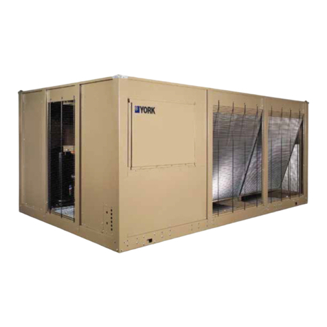
EUROKLIMAT EKS Series User manual

Series: EKS URL code for WebService2
Installation, operation and maintenance manual
Multi-scroll air cooled liquid chillers
Models: EKS/BS from 090-3-1 to 240-6-2 - EKS/HE from 055-2-1 to 180-6-2
TRANSLATION OF ORIGINAL INSTRUCTIONS
ORIGINAL LANGUAGE: ITALIAN
Rev. 2 - English –March 2018

3
www.euroklimat.it
1.0 GENERAL INFORMATION AND SAFETY
Index
1.0 GENERAL INFORMATION AND SAFETY ................................................................................................................. 4
1.1 UNIT IDENTIFICATION ........................................................................................................................................... 4
1.2 GUARANTEE AND AUTHORISED OPERATORS ....................................................................................................... 4
1.3 GENERAL AND SAFETY INFORMATION ................................................................................................................. 5
1.4 ATTACHED DOCUMENTS AND ASSISTANCE.......................................................................................................... 9
2.0 TECHNICAL INFORMATION ................................................................................................................................. 10
2.1 GENERAL DESCRIPTION AND MAIN PARTS .........................................................................................................10
2.2 LIMITATIONS OF USE...........................................................................................................................................12
2.3 TECHNICAL DATA ................................................................................................................................................14
2.4 SAFETY DEVICES ..................................................................................................................................................15
2.5 ACCESSORIES.......................................................................................................................................................15
3.0 HANDLING AND TRANSPORT ..............................................................................................................................19
3.1 GENERAL INFORMATION FOR TRANSPORT AND STORAGE................................................................................19
3.2 HANDLING...........................................................................................................................................................19
3.3 POSITIONING AND CLEAR SPACE ........................................................................................................................21
3.4 DIMENSIONS AND OPERATING SPACE...............................................................................................................22
3.5 UNPACKING AND VISUAL INSPECTIONS OF THE UNIT........................................................................................24
4.0 INSTALLATION AND CONNECTIONS....................................................................................................................26
4.1 INSTALLATION AREA AND SAFETY CONDITIONS.................................................................................................26
4.2 WATER CONNECTIONS........................................................................................................................................ 26
4.3 ELECTRICAL CONNECTIONS.................................................................................................................................27
5.0 START-UP AND CONTROL PANEL ........................................................................................................................29
5.1 FINAL CALIBRATION AND GUIDELINES FOR USE.................................................................................................29
5.2 START-UP AND PRELIMINARY CHECKS................................................................................................................30
5.3 PAUSE, SHUT-DOWN AND PROLONGED INACTIVITY..........................................................................................31
5.4 MICROPROCESSOR AND MAIN COMMANDS......................................................................................................31
6.0 MAINTENANCE AND FAULTS...............................................................................................................................44
6.1 GENERAL INFORMATION AND MAINTENANCE LOGICS......................................................................................44
6.2 ROUTINE MAINTENANCE ....................................................................................................................................44
6.3 SUPPLEMENTARY MAINTENANCE.......................................................................................................................46
6.4 CALIBRATIONS AND TROUBLESHOOTING........................................................................................................... 46
7.0 FINAL CONSIDERATIONS .....................................................................................................................................47
7.1 REPLACEMENT OF COMPONENTS ...................................................................................................................... 47
7.2 REPLACEMENT OF EQUIPMENT ..........................................................................................................................47
7.3 DECOMMISSIONING AND DISPOSAL................................................................................................................... 47
7.4 SAFETY SHEETS....................................................................................................................................................48
8.0 ANNEXES .............................................................................................................................................................54

4
www.euroklimat.it
1.0 GENERAL INFORMATION AND SAFETY
1.1 UNIT IDENTIFICATION
The equipment can be identified by the “Identification Plate (EC)” located on the machine. It contains the unit
SERIES number and the main technical data. The series number is essential for spare part requests or technical
assistance. We advise you to make a note of the machine number and keep it in a safe place. The plate must
always be fixed on the machine to provide anyone accessing it with the basic information about the equipment.
In the event of damage to the Identification Plate (EC) request a duplicate from the Manufacturer’s Technical
Assistance Office.
A further element of identification is represented by the “machine model”, which allows the type of construction,
important configurations and general characteristics to be traced. The machine model can always be found on
the identification plate and by putting together the information obtained from these two elements, it is possible
to gain a clear understanding of the equipment being used. The letters that make up the code consist of various
digits, each of which has a precise meaning. The example shown below indicates, conceptually, the contents of
the code and the different potential applications. Nonetheless, the Company reserves the right to change the
letters without notice.
1.2 GUARANTEE AND AUTHORISED OPERATORS
The machine that is the object of this manual is subject to the guarantee form described below, which is considered to have been accepted and
signed automatically by the client in the order phase to the Manufacturer with the signing in acceptance of the order confirmation. The supplying
company guarantees the excellent construction and quality of the supply, undertaking, at its own discretion, during the guarantee period
specified below, to repair or resupply, as soon as possible, parts containing acknowledged faulty materials, construction or workmanship, making
them unsuitable for their intended purpose. Provided this is not caused by negligence on the part of the customer, normal wear and tear or use,
negligent or inexpert use, damage by third parties, fortuitous events or events of force majeure or other causes, which cannot be attributed to
faults in the quality of the construction.
EKS -BP / BS / AS 110-3-1 1ps SP
SP –special configuration
Machine model
Equipment
Family group
Configuration
Version
BP = Base (plate evaporator)
BS = Base (shell and tube evaporator)
IP = Integrated (plate evaporator)
IS = Integrated (shell and tube evaporator)
BS = Business
BS/LN = Business + low noise
BS/SL = Business + Super low noise
HE = High efficiency
HE/LN = High efficiency + low noise
HE/SL = High efficiency + Super low noise
AS = Standard
DS = Desuperheater
HR = Total Recovery
Pump/s –only for IP and IS solution
1ps = 1 pump / standard pressure
2ps = 2 pumps / standard pressure
1px = 1 pump / “x” pressure
2px = 2 pumps / “x” pressure

5
www.euroklimat.it
1.0 GENERAL INFORMATION AND SAFETY
In this case, the supplying company may not be held liable for direct or indirect damage of any nature and for whatever reason. In the event of
the equipment being repaired or modified in some way by unauthorised personnel, the guarantee will automatically be invalidated. The aforesaid
guarantee conditions apply if the customer has complied with all of the contract obligations, particularly those regarding payments. It shall be
understood that none of the Manufacturer’s employees, workers, sales agents, service centers or anyone else is authorised to grant derogations
from the terms of the general guarantee conditions stated above. For further details, refer to the contract conditions stipulated at the time of
purchase, which constitute the only valid conditions.
Only the following professional figures may operate on the machine after receiving all of the necessary instructions contained in this manual:
Specialised electrical maintenance technician
The electrical maintenance technician must have general experience on electrical panels and specific experience on the board and electrical
components of chillers, or similar machines in the field of air conditioning. He may only carry out the operations specifically reserved for him set
out in this manual, following the instructions reported herein.
Specialised mechanical maintenance technician
The mechanical maintenance technician must have general experience of mechanics in general and specific experience on chillers, or similar
machines in the field of air conditioning. He may only carry out the operations specifically reserved for him set out in this manual, following the
instructions reported herein.
Refrigerator technician
The chiller refrigerator technician must have a special qualification obtained from an appropriate school on similar machines or under the
guidance of expert personnel. He must be in possession of the compulsory authorization, which must still be valid, in order to perform the
necessary operations. He may only carry out the operations specifically reserved for him set out in this manual, following the instructions
reported herein.
Carrier
He may only carry out the operations specifically reserved for him set out in this manual, following the instructions reported herein.
Person responsible for start-up and shut-down (Ordinary and mechanical operator)
After reading the information in this manual, the ordinary operator can carry out manual machine operations: start-up, shut-down, display
alarms. In any case, he can only carry out the operations specifically reserved for him set out in this manual, following the instructions reported
herein.
Safety manager
The safety manager is responsible for protecting and preventing company risks, as specified by the European Directive 89/391/EEC (Health and
Safety at Work). The safety manager will ensure that everyone operating on the machine has received all of the instructions relating to them
contained in this manual, including initial installation and start-up operations.
1.3 GENERAL AND SAFETY INFORMATION
During the design and construction phase, the machine manufacturer has paid particular attention to aspects, which may constitute a risk to the
health and safety of those working on it. Besides complying with the laws on the subject, he has adopted all of the good construction technique
rules. Nevertheless, caution is essential and safety is also in the hands of those working with the equipment. Read the instructions contained in
this manual carefully.
Inserting this machine into a system requires an overall project that takes legal and regulatory aspects into account. Do not tamper with, ignore,
eliminate or bypass the safety devices installed on the unit. Failure to comply with this requirement may lead to serious risks for people’s health
and safety. The aid of one or more assistants may be necessary in some phases; in this case, it is a good idea to provide appropriate training.
Keeping the equipment in conditions of maximum efficiency with programmed maintenance guarantees reliability and safety for operators.
Handle the machine using appropriate means and perform manoeuvres without risks to operators and people directly involved. Use the
equipment only for the uses foreseen by the manufacturer; any other use may cause risks to users. To sum up the above and highlight potential
risks related to improper handling of the unit, below is a list of the most important points and information or restrictions considered essential
for general safety.
The guarantee provided by the Manufacturer is rendered null and void with immediate effect if mechanical and/or electrical
modifications are carried out on the machine. Tampering in general that is not expressly authorised by the manufacturer and which does
not comply with the information set out in this manual will invalidate the guarantee.
THE GUARANTEE IS ONLY ACTIVATED AFTER ENTERING THE RELEVANT INTRODUCTORY FORM DULY COMPLETED AND COUNTERSIGNED
ON THE “WEB SERVICE” PORTAL (dedicated portal http://webservice.euroklimat.it/ ), WHICH CAN ALSO BE FOUND AT THE BACK OF THIS
MANUAL (ANNEX C).

6
www.euroklimat.it
1.0 GENERAL INFORMATION AND SAFETY
The contents of this manual must be read and fully understood before managing the units. This usage and maintenance manual
illustrates the operation and rules of usage and maintenance of the machines according to the Manufacturer’s criteria.
The Manufacturer of the equipment declines all responsibility for injury or damage resulting from failure to comply with the regulations
reported herein.
In the event of clarifications, further information or doubts of any kind, the Manufacturer is available to provide all of the relevant
instructions through his qualified technical personnel.
In order to facilitate identification and recognition of the machine, always refer to the technical data reported on the plate outside the
units and, in particular, the series number.
The machine must not be used under conditions other than those for which it was designed, not even for limited periods of time. The
incorporation of parts, which do not guarantee safety, is strictly forbidden.
The refrigerant fluid contained in the unit is R410A. The type of refrigerant used is reported on the technical plate on the machine. The
refrigerant safety data sheet can be found at the back of this manual.
The lubricating oil in the compressor is not dangerous; nonetheless, it must only be handled wearing gloves and it must not be
swallowed. The lubricating oil safety data sheet can be found at the back of this manual.
The procedures set out in the following chapters of this manual must be complied with for all work relating to installation, start-up, use,
modifications of conditions of use and operating modes, routine maintenance, inspections and periodic maintenance. This manual must
always be kept at hand for consultation.
This machine must only be used under the conditions foreseen by this usage and maintenance manual. Below we wish to draw USERS’
attention to various recommendations to avoid abnormal conditions of use; nonetheless, all other conditions of use not expressly
foreseen by this manual must be avoided.
Do not climb onto the machine. Do not operate the machine unless it has been installed correctly in the prescribed position. Do not start
the machine without closing the doors of the electrical panel properly.
Avoid getting close to the feed-in and air expulsion points. Do not clean the machine when it is in operation. Do not install the machine
in corrosive and/or explosive environments.
Do not disconnect or remove safety components. The machine must not be used under conditions other than those stated in this
manual.
The Manufacturer declines all responsibility for damage caused directly or indirectly to persons or property as a result of failure
to comply with these instructions.

7
www.euroklimat.it
1.0 GENERAL INFORMATION AND SAFETY
Analysis of residual risks
The manufacturer has made a precise analysis of the risks during the whole design and engineering phase of the product. However, despite the
careful design choices and targeted technical measures implemented, a few remaining residual risks should be taken into consideration.
Consequently, below is a list of the main residual risks and possible preventive action to be implemented.
-MECHANICAL RISKS: None, as all of the moving parts are protected by casing or grills.
-ELECTRICAL RISKS: None, as operations on the electrical panel may only be carried out by qualified and authorised personnel according
to the regulation and danger signs shown on the panel, which can only be opened using a special key with the main switch in the “OFF”
position.
-THERMAL RISKS:
▪Risk of burns (MEDIUM): on the chiller, the refrigerant reaches extremely high temperatures and pressures. The sections of
the circuit that are particularly critical for the risk of burns have been positioned to reduce the possibility of accidental contact
with these sections to a minimum. Other areas have been especially insulated and protected with special material. The
condensing coils can also reach very high temperatures.
This risk can be reduced by wearing appropriate clothing such as a work overall and gloves, which are suitable for the area
where the unit is installed.
▪Risk of inhalation and burns (LOW): the chiller is fitted with safety valves, which are activated automatically in the event of
pressure inside the refrigerant circuit exceeding a set threshold caused by anomalies or faults. When the threshold is
exceeded, the valve releases a quantity of gas at high pressure and temperatures into the atmosphere. Remember that the
activation of these devices is a rare but serious event, as it indicates a problem with the machine. Consequently, the valves
have been positioned to avoid being hit directly by the discharge jet.
One way of preventing and partially reducing the potential consequences consists of wearing appropriate clothing, such as
work overalls and gloves, which are suitable for the area where the unit is installed. An alternative way of mitigating this risk
consists of installing additional elements that can direct (in keeping with the technical requirements of the aforesaid valve)
the gas released into an area that is safe or separate from places, which might be occupied by workers.
-DANGERS FROM NOISE OR VIBRATIONS: None.
-DANGERS FROM HARMFUL SOURCES (electricity, static electricity, magnetic fields, radiation, lasers etc.): None
-OTHER SOURCES HARMFUL TO HEALTH (dust, gases, water, steam, fluids, mists, smoke, fire explosion, biological and microbiological
substances, chemical etc.): None
-ERGONOMIC RISKS (safety distances, ergonomic sizes and geometries, etc.):
▪Risk of cuts (MEDIUM): the chiller is an assembly of mechanical parts made of metal; consequently, there is a risk of cuts or
minor injuries caused by these parts (especially by the wings that make up the condensing coil). In order to reduce the
possibility of accidental contact with the parts to a minimum, you are strongly advised to wear appropriate clothing, such as
work overalls and gloves, which are suitable for the area where the unit is installed.
▪No other risks identified, provided the instructions and provisions relating to installation of the chiller, set out in this manual,
are complied with.
Personal protective equipment PPE
All workers involved in activities carried out near the chiller (whether the manufacturer’s technicians or a third parties) must be equipped with
appropriate personal protective equipment (PPE). The PPE used must comply with the national standards of reference and be in a good condition.
Damaged, worn or unfit PPE does not guarantee the requested and desired level of safety.
The following PPE represents the minimum compulsory equipment:
-Protective gloves, according to the specific risks, for example: welding, electrical risk, cut protection.
-Safety shoes
-Work clothes, according to the specific risks, for example: welding, electrical repairs, painting.
-Safety helmet, in the event of having to carry out activities involving the handling of suspended loads or activities involving
the need to work at a raised height from the ground.
-Harnesses or safety belts, in the event of having to carry out activities involving the need to work at raised height from the
ground.
-Acoustic protection devices (earphones or earplugs), in the event of having to carry out activities with the machine in
operation where noise levels exceed the maximum exposure requirements with reference to the national regulations.
-Protective eyewear, in the event of having to carry out activities, such as paining and welding.
-All other safety equipment required according to the risk evaluation developed by the subcontractors.
It is recommended that the compulsory safety devices (PPE) are identified correctly and indicated in these areas.

8
www.euroklimat.it
1.0 GENERAL INFORMATION AND SAFETY
General information for the customer and members of staff in charge
Before carrying out work on a chiller, it is necessary to check that the surrounding area is suitable for proceeding with the planned operations
and that all of the appropriate safety precautions have been taken. In particular, before starting work on the system, it is necessary to carry out
safety checks to ensure that the risk of injury or accidents is reduced to a minimum.
The following precautions must be taken before starting work on the refrigerant circuit:
-all members of staff and other workers in the area must be informed of the type of work carried out;
-the space around the work area must be marked off;
-working in confined spaces must be avoided and at least one escape route clear of obstacles must be guaranteed;
-equipment for extinguishing flames (CO2or dry type) must be available and serviceable in the surrounding areas;
-we strongly recommend the use of suitable, active gas detectors to warn workers of a possible leak or concentration of refrigerant
gas;
-all members of staff responsible for maintenance must be trained and understand the implications of the presence of refrigerant
gas;
-all technicians working with the refrigerant must be competent and authorised;
-all appropriate signs must be present;
-all of the necessary and appropriate equipment and instruments must be available.
Technical operators must always read this usage and maintenance manual carefully to ensure that they are aware of any particular, specific
requirements related to the equipment in question.
Putting into service can only be carried out by competent members of staff. Only one competent person in charge is responsible for the process
of putting into service.
Putting the water chillers into service correctly is essential to guarantee the correct working of the cooling system and minimise the risk of
abnormal functioning.
A chiller that is not installed properly and which has been put in operation can cause malfunctioning of the system, with potential risks to the
safety of workers, maintenance technicians and those in the surrounding area.

9
www.euroklimat.it
1.0 GENERAL INFORMATION AND SAFETY
1.4 ATTACHED DOCUMENTS AND ASSISTANCE
The following documents are supplied to the customer with the equipment:
•USAGE AND MAINTENANCE MANUAL –This document containing all of the information relating to installation, usage and maintenance of
the equipment.
•DECLARATION OF CONFORMITY - Document containing the “A” class EC type Declaration of Conformity, the PED Declaration of Conformity
and the Acceptance Certificate. Below is an example of the aforesaid document. As annex A at the back of this manual you can find the
previously mentioned Declaration of Conformity for the machine purchased.
•ELECTRICAL DIAGRAM –indicating all of the internal electrical connections and external interfaces and information about the various loads
for sizing of the protections and connections.
•SPARE PARTS LIST –List of the parts installed on the machine. It is possible to view the list of recommended spare parts. To view the
previously mentioned document, consult “WebService”.
•DIMENSIONAL DRAWING –Representing the construction detail of the equipment with special instructions for the connections and
interfaces to the surrounding systems. To view the previously mentioned document, consult “WebService”.
For further documentation, consult the documents online 24h 365 days a year at the web address http://webservice.euroklimat.it/ (accessing
your personal account with ID and password).
Remember that the maintenance manager (company and/or employee) is responsible for compiling the:
MAINTENANCE HANDBOOK –It will contain a list of the operations of routine maintenance and is designed to record all operations carried out,
including supplementary maintenance.
Indications on the recommended intervals of maintenance, which must be reported in the handbook, can be found by consulting the norm EN
378-4:2017 Refrigeration systems and heat pumps –Safety and environmental requirements –Part 4: Management, maintenance, repair and
recovery. An extract of the previously mentioned regulation is reported in annex B at the back of the manual.
The manufacturer relies on external service centres, which are assessed and subsequently “Authorised” to operate on the equipment.
Unauthorised members of staff are not permitted to operate on the units. In the event of a fault or anomaly, contact the authorised service
centre directly. The request must be made indicating the sensitive data of the equipment, which can be found on the identification plate
(particularly the series number). It is necessary to report the type of fault including the error identification code that appears on the display, as
well as the indicative operating time. Remember to arrange clear spaces for the machine free of obstacles to facilitate intervention by operators.

10
www.euroklimat.it
2.0 TECHNICAL INFORMATION
2.1 GENERAL DESCRIPTION AND MAIN PARTS
The machines in this series are designed and built for use in air conditioning systems and industrial process cooling. They are fitted with a
microprocessor control system (see chapter 5), which allows the internal functions of the unit to be controlled, and interfacing with external
supervision systems. The units are thoroughly tested in the factory and supplied complete with refrigerant charge and lubricating oil.
In order to guarantee maximum performance and operator safety before installation, competent, authorised personnel must carry out design
tests and checks on the product and environment, analysing all of the foreseeable critical points during the lifespan of the equipment. The useful
life of the machine in normal conditions is estimated to be about 25,000 working hours and no more than ten years; when this period is reached,
a general revision is needed to upgrade the product and continue using it safely
. In this case, the type is:
-Condensed liquid chillers with axial air flow fans suitable for outdoor installation
The appliances are essentially composed of a refrigerant circuit and a hydraulic circuit, which allow the cooling of pure water or glycol mixtures
(with ethylene glycol or propylene) up to a maximum concentration of 40% in weight (
1
). In the refrigerant circuit, cooling is achieved by means
of a thermodynamic cycle thanks to the action of a compressor, a finned coil exchanger (source), a plate or shell and tube (users) exchanger and
an expansion valve that controls the flow of the refrigerant.
In terms of hydraulics, depending on the configurations and accessories, circulation pumps, storage tanks, filling groups etc. can be included. All
of these appliances are supplied inside a containing structure and are controlled by an electrical panel and microprocessor system designed
specifically for this purpose.
Below are a few examples of the numerous configurations and combinations possible for this series of chillers.
•EKS BS –Business; configuration “2V”; basic version without pump and without tank; plate evaporator; single circuit with compressors
in trio configuration; standard model
Accessories: Condensing coil protective grills; High and low pressure manometers
EKS –BP / BS/AS 090-3-1
1
NOTE: for versions with pump(s) on board, it is necessary to use special mechanical seals for concentrations of glycol over 40%. Contact the
Manufacturer’s Technical Office for further information.

11
www.euroklimat.it
2.0 TECHNICAL INFORMATION
•EKS HE –High Efficiency; configuration “3V”; basic version without pump and without tank; plate evaporator; dual circuit with
compressors in tandem configuration; low noise version; standard model
Accessories: Condensing coil protective grills; High and low pressure manometers
EKS –BP / HE/LN/AS 080-4-2
•EKS BS –Business; configuration “4V”; basic version without pump and without tank; shell and tube evaporator; dual circuit with
compressors in trio configuration; standard model
Accessories: Condensing coil protective grills; High and low pressure manometers
EKS –BS / BS/AS 240-6-2

12
www.euroklimat.it
2.0 TECHNICAL INFORMATION
•EKS HE –High Efficiency; configuration “5V”; integrated version with double pump (in service + stand by) with tank; shell and tube
evaporator; dual circuit with compressors in trio configuration; standard model
Accessories: Condensing coil protective grills; High and low pressure manometers
EKS –IS / HE/AS 180-6-2 2ps
2.2 LIMITATIONS OF USE
The units are versatile and can operate under extremely different working conditions depending on the installation characteristics and typology.
However, there are limit conditions, which must not be exceeded in order to avoid causing serious damage to the functionality and risks to
operators’ safety. Below are graphs indicating the operation limits of use and indications for the fluid mixtures to be used.
EKS/BS Business
Operating area
Operating at partial load
Operating area with modulating fan speed control (option)
Operating area with EC fans (option)
SP –Special configuration (available on request)
T air: Outdoor air temperature [C°]
LWT: Evaporator outlet temperature [C°]
MEG: Mixture of ethylene glycol
Pure water
T air
[°C]
LWT [°C]
Evaporator
COOLING OPERATION LIMITS

13
www.euroklimat.it
2.0 TECHNICAL INFORMATION
EKS/HE High Efficiency
EKS/BS Business –EKS/HE High Efficiency
Mixture of ethylene glycol (Meg) –Correction factor
If a mixture of ethylene glycol is used instead of pure water, it causes a change in the performance of the unit. Remember that the choice of the
correct percentage of glycol to be used is determined taking into consideration not only the temperature of the chilled fluid, but also the
temperature of the outside air and/or the environment near the water circuit pipes.
For correct data, please use the correction factor indicated in the following table:
Meg
0 (pure water)
Meg 20% (*)
Meg 30% (*)
Meg 40% (*)
Freezing point
0°C
-8,9°C
-15,8°C
-24,8°C
CcCF
1
0,980
0,974
0,965
CcCF: Cooling capacity correction factor
(*): For mixtures of ethylene glycol (Meg) over 20% or for other types of anti-freeze solutions, please contact the manufacturer,
for further technical checks.
Operating area
Operating at partial load
SP –Special configuration (available on request)
T air: Outdoor air temperature [C°]
LWT: Evaporator outlet temperature [C°]
MEG: Mixture of ethylene glycol
Operating area with Desuperheater
T out: Desuperheater water outlet temperature [C°]
LWT: Evaporator outlet temperature [C°]
MEG: Mixture of ethylene glycol
Operating area with Heat Recovery
T out: Total recovery exchanger water outlet temperature [C°]
LWT: Evaporator outlet temperature [C°]
MEG: Mixture of ethylene glycol
Pure water
T air
[°C]
LWT [°C]
Evaporator
COOLING OPERATION LIMITS
Pure water
Pure water
LWT [°C]
Evaporator
LWT [°C]
Evaporator
T out
[°C]
T out
[°C]
DESUPERHEATER OPERATION LIMITS
HEAT RECOVERY OPERATION LIMITS

14
www.euroklimat.it
2.0 TECHNICAL INFORMATION
Mixture of propylene glycol (Mpg) –Correction factor
If a mixture of propylene glycol is used instead of pure water, it causes a change in the performance of the unit. Remember that the choice of
the correct percentage of glycol to be used is determined taking into consideration not only the temperature of the chilled fluid, but also the
temperature of the outside air and/or the environment near the water circuit pipes.
For correct data, please use the correction factor indicated in the following table:
Mpg
0 (pure water)
Mpg 20% (*)
Mpg 30% (*)
Mpg 40% (*)
Freezing point
0°C
-7,4°C
-13,1°C
-21,5°C
CcCF
1
0,950
0,9375
0,925
CcCF: Cooling capacity correction factor
(*): For mixtures of propylene glycol (Mpg) over 20% or for other types of anti-freeze solutions, please contact the manufacturer,
for further technical checks.
For all of the models in the EKS Business and High Efficiency series, the following tables show the minimum and maximum evaporator water flow
values, to be taken into consideration and evaluated during the sizing of pumps, storage tanks and water circuit. These values must be considered
as operation limits. If the installation or type of use requires working outside these limits, the manufacturer must carry out a technical check to
ensure the correct and efficient working of the chiller.
Evaporator
water flow
[m3/h]
EKS BS - Business
090-3-1
100-3-1
110-3-1
120-3-1
120-4-2
140-4-2
160-4-2
180-6-2
200-6-2
220-6-2
240-6-2
Minimum
31,7
34,0
36,3
38,1
44,4
48,1
51,2
57,9
69,2
72,5
75,5
Maximum
47,5
51,1
54,5
57,2
66,6
72,2
76,9
86,8
103,9
108,8
113,3
Evaporator
water flow
[m3/h]
EKS HE –High Efficiency
055-2-1
060-2-1
070-2-1
080-4-2
090-4-2
100-4-2
110-4-2
120-4-2
140-4-2
160-4-2
180-6-2
Minimum
21,6
24,2
26,9
29,9
33,8
37,0
43,2
48,4
53,7
62,2
71,0
Maximum
32,4
36,3
40,3
44,9
50,7
55,6
64,9
72,6
80,6
93,3
106,5
2.3 TECHNICAL DATA
(1) Reference conditions: performance based on: Condenser air intake temperature 35°C –Evaporator water temperature IN/OUT = 12/7°C - Fluid: pure water –Condensing coil:
Microchannel
(2) Reference conditions: sound power level in compliance with ISO 3744 –Sound pressure level (average) at 10-meter distance, unit in a free field on a reflective surface; non-binding
value obtained from the sound power level.
EKS BS - Business
090-3-1
100-3-1
110-3-1
120-3-1
120-4-2
140-4-2
160-4-2
180-6-2
200-6-2
220-6-2
240-6-2
Cooling capacity (1)
[kW]
244
262
280
294
342
371
395
446
533
559
582
Compressor power input (tot.) (1)
[kW]
81,6
90,6
99,8
108,0
104,4
122,8
139,6
174,0
177,4
195,2
213,6
Fan power input (tot.) ST version
[kW]
6,0
6,0
6,0
6,0
9,1
9,1
9,1
9,1
12,1
12,1
12,1
Fan power input (tot.) LN / SL version
[kW]
8,4
8,4
8,4
8,4
12,6
12,6
12,6
12,6
16,8
16,8
16,8
Supply
V/ph/Hz
400/3/50
400/3/50
400/3/50
400/3/50
400/3/50
400/3/50
400/3/50
400/3/50
400/3/50
400/3/50
400/3/50
Total installed power (ST version)
[kW]
116
125
134
143
156
174
191
228
250
267
285
Maximum absorbed current
Full load (ST version)
[A]
212
229
246
263
285
319
354
416
458
492
527
Total sound power (ST version) (2)
[db(A)]
91
92
94
94
92
94
96
93
95
97
98
Total sound pressure (ST version) (2)
[db(A)]
58
60
61
62
60
62
63
61
63
64
65
Total sound power (LN version) (2)
[db(A)]
87
88
90
90
88
90
92
89
91
93
94
Total sound pressure (LN version) (2)
[db(A)]
54
56
57
58
56
58
59
57
59
60
61
Total sound power (SL version) (2)
[db(A)]
85
86
88
88
86
88
90
87
89
91
92
Total sound pressure (SL version) (2)
[db(A)]
52
54
55
56
54
56
57
55
57
58
59

15
www.euroklimat.it
2.0 TECHNICAL INFORMATION
(1) Reference conditions: performance based on: Condenser air intake temperature 35°C –Evaporator water temperature IN/OUT = 12/7°C - Fluid: pure water –Condensing coil:
Microchannel
(2) Reference conditions: sound power level in compliance with ISO 3744 –Sound pressure level (average) at 10-meter distance, unit in a free field on a reflective surface; non-binding
value obtained from the sound power level.
2.4 SAFETY DEVICES
During the design and construction phase, the Manufacturer has included safety devices (active and passive) in keeping with the current
legislation in the country of use. It is necessary to check, in particular, and on ordering the equipment, that the standard fittings or suppliable
options correspond to the requests and usage requirements. Below are the main safety devices installed on the machine.
SAFETY VALVES
Safety valves are installed on the gas circuit upstream and downstream of the compressor (C). Valve “A”, high-pressure side,
is always installed on the equipment, while valve “B” low pressure is only installed if required by the regulations of the
country of installation. The function of the valves is extremely important because in all abnormal working conditions, or
when there is a risk of damage to people or property, the device opens the opening, the refrigerant comes out of the circuit
and the pressure returns within the safety parameters. It is essential to ensure correct maintenance of the equipment to
allow the valves to be activated properly in the event of an emergency.
2.5 ACCESSORIES
There are various accessories for this equipment, which serve different purposes. To see a complete list of accessories, please refer to the
technical product catalogue, which can be requested from the Manufacturer and directly from the Company’s Sales Office. This section only lists
the main accessories that substantially change the machines’ configuration when installed.
ANTI-VIBRATION MOUNTS (Optional accessory)
There are two types of anti-vibration mounts: standard or anti-seismic. The choice obviously depends on the requirements and needs of the
place of installation. Anti-seismic mounts guarantee excellent performance also in places where earthquakes are frequent. The mounts are
supplied separately from the chiller, in assembly kits, since assembly in the factory could result in serious damage during loading/unloading and
transport, mainly due to the uncontrollability of the resulting oscillations. They must be connected to the machine during the installation phase,
immediately before set up.
EKS HE –High efficiency
055-2-1
060-2-1
070-2-1
080-4-2
090-4-2
100-4-2
110-4-2
120-4-2
140-4-2
160-4-2
180-6-2
Cooling capacity (1)
[kW]
167
186
207
231
260
285
333
373
414
479
547
Compressor power input (tot.) (1)
[kW]
44,4
50,5
57,8
61,9
70,0
79,7
88,8
100,9
115,5
127,2
155,8
Fan power input (total) ST version
[kW]
6,4
7,5
8,7
9,7
11,2
11,2
12,9
15,0
17,4
19,3
21,8
Fan power input (tot.) LN / SL version
[kW]
5,8
6,6
7,6
8,7
9,9
9,9
11,6
13,2
15,2
14,5
19,0
Supply
V/ph/Hz
400/3/50
400/3/50
400/3/50
400/3/50
400/3/50
400/3/50
400/3/50
400/3/50
400/3/50
400/3/50
400/3/50
Total installed power
[kW]
70
80
90
102
113
123
141
159
180
199
238
Maximum absorbed current
Full load
[A]
124
142
161
175
194
211
248
285
323
360
426
Total sound power (ST version) (2)
[db(A)]
93
93
94
94
94
95
96
96
97
98
97
Total sound pressure (ST version) (2)
[db(A)]
60
60
61
61
62
62
63
63
64
66
64
Total sound power (LN version) (2)
[db(A)]
89
89
90
90
90
91
92
92
93
94
93
Total sound pressure (LN version) (2)
[db(A)]
56
56
57
57
58
58
59
59
60
62
60
Total sound power (SL version) (2)
[db(A)]
87
87
88
88
88
89
90
90
91
92
91
Total sound pressure (SL version) (2)
[db(A)]
54
54
55
55
56
56
58
57
58
60
58
STANDARD ANTI-VIBRATION SPRING
MOUNT
ANTI-VIBRATION SEISMIC SPRING
MOUNT

16
www.euroklimat.it
2.0 TECHNICAL INFORMATION
Assembling the mounts is extremely simple as fixing holes are already provided in the base of the refrigeration unit and the “nut/locknut” system
on the main pivot of the support makes their installation quick and simple. After positioning the supports and placing the chiller, it is possible to
adjust the height using the adjusting nut, making sure that the machine is perfectly level. A drawing is included with the documents supplied
with the chiller, indicating the correct assembly procedure for this accessory, which takes into account the distribution of the weights inside the
machine. The supplied mounts may differ to adapt to the real distribution needs of the loads of the chiller; in this case, it is necessary to pay
attention to the indications in the diagram and follow the instructions carefully.
The installation procedure for the anti-vibration mounts is illustrated in the following paragraph.
▪INSTALLATION OF THE ANTI-VIBRATION SPRING
JACKS COMPONENTS (fig.1)
E1 M16x100mm grain with lodging for 8 mm allen key
E2 - E6 Low nut M16 - UNI 5589
E3 Broken elastic washer UNI 1751
E4 Steel-Disc Ø 80x5 for M16 jack
E5 High nut M16 - UNI 5587
Configuration of the jack before the insertion inside the anti-vibration mount:
8 mm allen key Simple key of the 24TH
PROCEDURE TO INSERT THE JACK INSIDE THE ANTI-VIBRATION MOUNT.
fig.2 Insert the M16x100 mm threaded stud (E1) in the threaded hole in the mount upper plate and using an 8mm allen key fit it in for 15-
20 mm (A1).
fig.3 Using the simple key of the 24TH, fit the M16 grain (E1) mounted on the anti-vibration mount in the hole of the machines base, with
steel nut (E6). In this way, the anti-vibration mount is ready to be installed as shown in the next page.
BE CAREFUL:
The antivibration mount must be placed under the machine according to the image presented in the “foot print” scheme in the following pages.

17
www.euroklimat.it
2.0 TECHNICAL INFORMATION
INSTALLATION
A. Place the machine at a height that allows the operator to put in the machine holes (A1) the jacks installed previously in the anti-vibration
mounts.
B. Through the hole (B1) fix the anti-vibrating using the low nut (E2) interposing a broken elastic washer (E3).
C. Place the machine on the support points at the same time to apply the load simultaneously on all the anti-vibration mounts. Fix the machine
level using the high nuts (E5). When the unit is correctly aligned fix the nuts (E2).
D. At the end of these operations the machine should be elastic on the anti-vibration mounts.
The detailed instructions for securing an EKS machine –IS / BS/AS 090-3-1 2ps are shown by way of example
A specific “Installation Instructions Manual” for the anti-vibration mounts will be supplied with every ANTI-VIBRATION kit ordered, chosen for
the special needs of the chiller purchased. See package / box containing the anti-vibration mounts.

18
www.euroklimat.it
2.0 TECHNICAL INFORMATION
HYDRAULIC VERSIONS
These accessories are of a hydraulic nature and offer various possible configurations: 1 or 2 circulation pumps; storage tank; water filters and
safety valves. The real configurations will be designed and checked in the order phase, using the special technical documents and, if necessary,
requesting assistance from the Manufacturer.
The above diagrams are only intended to show examples of installation. You are strongly advised to check which is the appropriate configuration
for the equipment that best suits your particular needs and use and/or request the specific documentation.
PARTIAL HEAT RECOVERY (DESUPERHEATER) - DS
Partial heat recovery, also otherwise defined as desuperheater, allows
part of the condensation heat to be reused, which is normally dispersed
and consequently eliminated by the main condenser. With this “DS”
configuration, an additional exchanger heats water for uses, such as post-
heating, sanitary circuit or other.
The system supplies heat without requiring any further consumption of
energy, taking advantage of the desuperheating phase of the hot gas and
not intervening in the condensation phase. Because of its structure, the
desuperheater has a power limit estimated at around 20% of the cooling
capacity produced, but which varies depending on the size of the unit,
the nominal working conditions and the heat recovery conditions
required.
CONNECTION WITH DESUPERHEATER
TOTAL HEAT RECOVERY –HR
Total heat recovery allows all of the condensation heat to be reused,
which is normally dispersed and consequently eliminated by the main
condenser. With the “HR” configuration, it is possible to reheat the water,
thanks to an additional exchanger, and use it for post-heating, sanitary
circuit or other.
There are two possibilities for the recovery connection: with a series
circuit or parallel circuit. Each of these solutions has its advantages and
disadvantages. The construction diagrams vary considerably. The series
circuit is much simpler than the parallel circuit, which, on the other hand,
requires more refrigeration components. For further information,
contact the Manufacturer’s Sales Office directly.
CONNECTION WITH TOTAL HEAT RECOVERY
BASIC SOLUTION “B”
INTEGRATED SOLUTION “I” WITH PUMP AND TANK
INTEGRATED SOLUTION “I” WITH PUMP, RESERVE PUMP AND TANK
Limite batteria
EKS
Euroklimat
EVAPORATORE
Resistenza antigelo raccomandata
Resistenza antigelo
opzionale
Limite batteria EKS Euroklimat
Resistenza antigelo
opzionale
Resistenza antigelo
raccomandata
EVAPORATORE
EVAPORATORE
Limite batteria EKS Euroklimat
Resistenza antigelo
opzionale
Resistenza antigelo
raccomandata
DESURRISCALDATORE
Resistenza antigelo
opzionale
Resistenza antigelo
raccomandata
Limite batteria
EKS
Euroklimat
EVAPORATORE
EVAPORATORE
RECUPERATORE DI CALORE
Limite batteria
EKS
Euroklimat
Resistenza antigelo
opzionale
Resistenza antigelo
raccomandata
Valvola a 3 vie
raccomandata

19
www.euroklimat.it
3.0 HANDLING AND TRANSPORT
LEGEND
3.0 HANDLING AND TRANSPORT
3.1 GENERAL INFORMATION FOR TRANSPORT AND STORAGE
The machine transport method must be compatible with the loading system used in the production plant and the one at the unloading site, as
well as with the standard requirements. Loading from above must be possible for this series of machines. The following paragraphs contain
further detailed information.
If the machine is not installed upon receipt, but stored for a long period of time, it is necessary to ensure that the place of storage is:
- a protected environment
- protected from the sun’s rays, rain, sand or wind
- the internal temperature of the place is between -10°C (minimum) and 50°C (maximum)
- the relative internal humidity of the place does not exceed 90%
Strictly avoid placing objects on top of the unit because it could seriously damage the equipment and various mechanical parts and the
safety requirements for storage, subsequent installation and operations would no longer be guaranteed.
Do not leave the units enclosed in the packaging in particularly sunny areas, as the internal temperature could reach the safety device
activation values.
3.2 HANDLING
Lifting and handling must be carried out using appropriate means and by experienced members of staff who are trained and authorised to
perform these types of operations.
LIFTING WITH ROPES
The machines in this range are of a considerable size and consequently, it is necessary to use a rope system and a special sling bar to safeguard
the parts of the unit and avoid crushing, which could increase safety risks and damage to the chiller.
LIFTING PROCEDURE
A–Choosing and preparing the rope lifting kit.
The choice of the right rope lifting kit, which must have a maximum load capacity compatible with the weight of the chiller, is vitally important.
It is equally important to adjust the straps properly to ensure the safe handling of the unit for people and property around the operating area.
Adjustments must be carried out competently to keep the chiller in as horizontal a position as possible, parallel to the ground, to avoid damage.
B–Connect the lifting straps in the points as shown in the figure below. Each unit is built with four lifting eyebolts,
positioned and arranged in the correct stress points (see picture at the side shown by way of example). The use of
other parts of the unit as hooking or lifting points is strictly forbidden. Failure to comply with this requirement could
seriously compromise the unit and cause serious accidents (also fatal) involving people and/or property.
Before proceeding with handling, you are advised to check that all of the mechanical parts for connecting the
machine and the lifting device are tight, in good conditions and do not show any obvious flaws or signs of damage.
Water pump
acqua
Shut-off valve
3-way valve
Non-return valve
Manometer
Vent valve
Safety valve
Water filter
Anti-freeze heater
Anti-vibration joints
Differential pressure switch
Heat exchanger
Filling assembly
Buffer tank

20
www.euroklimat.it
3.0 HANDLING AND TRANSPORT
C–Tighten the lifting straps gradually, making sure that they are positioned correctly and checking that they do not crush the upper part of the
unit. The straps must not come into contact with the structure of the chiller in any way.
D–Proceed with lifting and handling, paying particular attention to the people and objects in the surrounding area, which must be marked off
and kept clear, as far as possible. Only qualified and authorised personnel are allowed to carry out this type of operation.
Transport must be carried out taking great care, avoiding using the parts of the equipment as stress points. To avoid damage when
moving the units, they must always be kept in the operating position.
Handling must be carried out with the water circuit completely empty.
Lifting must be carried out using straps or ropes. Use a sling bar making sure that there is no pressure on the upper edges of the machines
or packaging.
CHILLER WEIGHTS
Please refer to the following summary tables, indicating the weights of the different sizes depending on their configuration. Take care when
reading the aforesaid tables to avoid errors resulting from an incorrect interpretation of the configuration of the purchased chiller.
Range EKS/BS business
Unladen weights
090-3-1
100-3-1
110-3-1
120-3-1
120-4-2
140-4-2
160-4-2
180-6-2
200-6-2
220-6-2
240-6-2
Basic Solution / BP
(plate evaporator)
kg
1.780
1.800
1.815
1.825
2.610
2.635
2.680
2.985
3.470
3.495
3.520
Basic Solution / BS
(shell and tube evaporator)
kg
1.860
1.870
1.885
1.900
2.690
2.715
2.745
3.050
3.580
3.615
3.640
Integrated Solution / IP
(plate evaporator)
kg
1.915
1.940
1.950
1.960
2.815
2.840
2.880
3.190
3.675
3.700
3.725
Integrated Solution / IS
(shell and tube evaporator)
kg
2.000
2.010
2.020
2.040
2.915
2.940
2.970
3.275
3.770
3.805
3.830
Basic Solution / BP (plate evaporator) /
LN/SL Low Noise Version
kg
1.855
1.875
1.890
1.900
2.750
2.780
2.820
3.175
3.660
3.685
3.710
Basic Solution / BS (shell and tube
evaporator) / LN/SL Low Noise Version
kg
1.935
1.945
1.960
1.975
2.830
2.855
2.885
3.240
3.770
3.615
3.830
Integrated Solution / IP (plate
evaporator) / LN/SL Low Noise Version
kg
1.990
2.015
2.025
2.035
2.955
2.980
3.020
3.380
3.865
3.670
3.915
Integrated Solution / IS (shell and tube
evaporator) / LN/SL Low Noise Version
kg
2.070
2.085
2.100
2.110
3.055
3.080
3.110
3.465
3.960
3.805
4.020
This manual suits for next models
24
Table of contents
Popular Chiller manuals by other brands

Hitecsa
Hitecsa EKWXA 7002.4 Installation, operation & maintenance manual

AERMEC
AERMEC NRV 0550 Installation and maintenance manual

Trane
Trane TCCA ACCOMPANIMENT TO THE INSTALLATION, OPERATION AND MAINTENANCE MANUAL

MPC
MPC UC006 operating manual

Trane
Trane R Series Installation operation & maintenance

CLIVET
CLIVET MSE-XSC3 90.4 Installation and operating manual