manuals.online logo
Brands
  1. Home
  2. •
  3. Brands
  4. •
  5. AERMEC
  6. •
  7. Chiller
  8. •
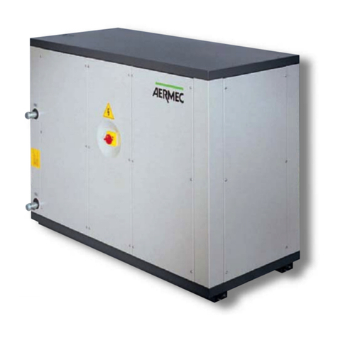
  9. AERMEC NRW Series Installation and operation manual

AERMEC NRW Series Installation and operation manual

AERMEC S.P.A.
ISO 9001 - Cert. nº 0128/1
C
E
R
T
I
F
I
E
D
Q
U
A
L
I
T
Y
S
Y
S
T
E
M
INRWPW
0203
65579.16
Refrigeratori e pompe di calore acqua acqua
Water to water chillers and heat pumps
NRW NRW-H NRW-E
R22 - R407C
MM
MMAA
AANN
NNUU
UUAA
AALL
LLEE
EE
TT
TTEE
EECC
CCNN
NNII
IICC
CCOO
OO
EE
EE
DD
DD’’
’’II
IINN
NNSS
SSTT
TTAA
AALL
LLLL
LLAA
AAZZ
ZZII
IIOO
OONN
NNEE
EE
TT
TTEE
EECC
CCHH
HHNN
NNII
IICC
CCAA
AALL
LL
AA
AANN
NNDD
DD
II
IINN
NNSS
SSTT
TTAA
AALL
LLLL
LLAA
AATT
TTII
IIOO
OONN
NN
BB
BBOO
OOOO
OOKK
KKLL
LLEE
EETT
TT
Sostituisce il:
Replace:
65579.12 / 0101
3
II
IINN
NNDD
DDII
IICC
CCEE
EE
••
••
CC
CCOO
OONN
NNTT
TTEE
EENN
NNTT
TTSS
SS
INFORMAZIONI GENERALI
•
GENERAL INFORMATION
5
CARATTERISTICHE GENERALI
•
FEATURES
Descrizione dell’unità • Unit description
Componenti principali • Main components 6
Descrizione dei componenti • Component description 7
Organi di regolazione • Controls 8
Organi di sicurezza e di controllo • Safety and controls devices
Accessori • Accessories 10
Tabella di compatibilità degli accessori • Accessories compatibility table 11
Dati tecnici • Technical data 12
MISURE DI SICUREZZA
•
SAFETY MEASURES
Usi impropri • Improper uses 20
CARATTERISTICHE GENERALI
•
FEATURES
Criteri di scelta • Selection 21
Limiti di funzionamento • Operating limits 23
Potenza frigorifera totale ed assorbimento elettrico totale • Cooling capacity and total input power 24
Potenza termica totale ed assorbimento elettrico totale • Heating capacity and total input power 30
Perdite di carico • Pressure drops 32
Prevalenza disponibile • Effective pressure 33
Perdita di carico filtro acqua • Water filter pressure drops
Tabelle di correzione • Correction tables 34
Pressione e potenza sonora • Sound pressure and power level
Campo di taratura dei parametri di controllo • Control parameter setting range
Taratura dispositivi di protezione • Protection device settings 35
Tabelle di correzione • Correction tables
Linee frigorifere NRW-E • NRW-E refrigerant lines 36
INSTALLAZIONE
•
INSTALLATION
Circuito idraulico • Hydraulic circuit 37
Collegamenti elettrici • Wiring connections
Prima della messa in funzione • Before start-up
Messa in funzione dell’unità • Start-up of the unit
Caricamento / scaricamento impianto • Charging / draining the installation 39
CARATTERISTISCHE
•
FEATURES
Dimensioni • Dimensions 41
Spazi tecnici minimi • Minimum technical space 43
Dati accessori • Accessories data 44
Legenda per circuito frigorifero • Chiller circuit legend
Lay-out circuito frigorifero e dispositivi di controllo • Lay-out of chiller circuit and control devices 45
Legenda per schemi elettrici • Wiring diagrams key
Dati elettrici • Electrical data 48
Schemi elettrici • Wiring diagrams 49
4
II
IINN
NNFF
FFOO
OORR
RRMM
MMAA
AAZZ
ZZII
IIOO
OONN
NNII
II
GG
GGEE
EENN
NNEE
EERR
RRAA
AALL
LLII
II
••
••
GG
GGEE
EENN
NNEE
EERR
RRAA
AALL
LL
II
IINN
NNFF
FFOO
OORR
RRMM
MMAA
AATT
TTII
IIOO
OONN
NN
NRW NRW-H
DICHIARAZIONE DI CONFORMITÀ
Noi, firmatari della presente, dichiariamo sotto la nostra
esclusiva responsabilità, che la macchina in oggetto è
conforme a quanto prescritto dalle seguenti Direttive:
- Direttiva macchine 89/392/CEE e modifiche 91/368/CEE,
93/44/CEE, 93/68/CEE
- Direttiva bassa tensione 73/23/CEE
- Direttiva compatibilità elettromagnetica EMC 89/336/CEE.
NRW E
È fatto divieto di mettere in servizio il prodotto, oggetto
della dichiarazione, prima che l’apparecchio in oggetto a
cui sarà incorporato od assiemato, sia stato dichiarato
conforme alle disposizioni della Direttiva.
DICHIARAZIONE DI CONFORMITÀ
Noi, firmatari della presente, dichiariamo sotto la nostra
esclusiva responsabilità, che la macchina in oggetto è
conforme a quanto prescritto dalle seguenti Direttive:
- Direttiva macchine 89/392/CEE e modifiche 91/368/CEE,
93/44/CEE, 93/68/CEE
- Direttiva bassa tensione 73/23/CEE
- Direttiva compatibilità elettromagnetica EMC 89/336/CEE.
NRW NRW-H
DECLARATION OF CONFORMITY
We declare under our own responsability that the above
equipment complies with provisions of the following
Standards:
- Equipment Standard 89/392/EEC and amendments
91/368/EEC, 93/44/EEC, 93/68/EEC
- Low voltage Standard 73/23/EEC
- Electromagnetic compatibility Standard EMC 89/336/EEC.
NRW E
It is not allowed to operate the appliance object of the
Declaration before the appliance it will incorporated to or
assembled with, is declared in compliance with the provi-
sions of the Directive.
DECLARATION OF CONFORMITY
We declare under our own responsability that the above
equipment complies with provisions of the following
Standards:
- Equipment Standard 89/392/EEC and amendments
91/368/EEC, 93/44/EEC, 93/68/EEC
- Low voltage Standard 73/23/EEC
- Electromagnetic compatibility Standard EMC 89/336/EEC.
NRW
NRW-H
modello:
model:
numero di serie:
serial number:
Bevilacqua, 1/1/2002 La Direzione Marketing – Marketing Director
Luigi ZUCCHI
AERMEC S.p.A.
I-37040 Bevilacqua (VR) Italia – Via Roma, 44
Tel. (+39) 0442 633111
Telefax 0442 93730 – (+39) 0442 93566
www.aermec.com - [email protected]
5
II
IINN
NNFF
FFOO
OORR
RRMM
MMAA
AAZZ
ZZII
IIOO
OONN
NNII
II
GG
GGEE
EENN
NNEE
EERR
RRAA
AALL
LLII
II
••
••
GG
GGEE
EENN
NNEE
EERR
RRAA
AALL
LL
II
IINN
NNFF
FFOO
OORR
RRMM
MMAA
AATT
TTII
IIOO
OONN
NN
OSSERVAZIONI
Questo è uno dei due manuali che descrivono la macchina
qui rappresentata. I capitoli descritti nella tabella sottoripor-
tata, sono presenti o assenti a seconda del tipo di manuale.
Tecnico Uso
Informazioni generali x x
Caratteristiche: x
Descrizione della macchina
versioni, accessori x
Caratteristiche tecniche: x
Dati tecnici x
Dati accessori x
Schemi elettrici x
Misure di sicurezza: x x
Precauzioni generali x x
Usi impropri x x
Installazione: x
Trasporto x
Installazione unità x
Procedure per la messa
in funzione x
Uso x
Manutenzione ordinaria x
Individuazione guasti x
Conservare i manuali in luogo asciutto, per evitare il dete-
rioramento, per almeno 10 anni per eventuali riferimenti
futuri.
Leggere attentamente e completamente tutte le informa-
zioni contenute in questo manuale. Prestare particolar-
mente attenzione alle norme d’uso accompagnate dalle
scritte “PERICOLO” o “ATTENZIONE” in quanto, se non
osservate, possono causare danno alla macchina e/o a per-
sone e cose.
Per anomalie non contemplate da questo manuale, interpel-
lare tempestivamente il Servizio Assistenza di zona.
AERMEC S.p.A. declina ogni responsabilità per qualsiasi
danno dovuto ad un uso improprio della macchina, ad una
lettura parziale o superficiale delle informazioni contenute
in questo manuale.
Il numero di pagine di questo manuale è: 60.
REMARKS
This is one of a set of two manuals that describe this machi-
ne. The chapters described in the table below are only
included if relevant to the specific manual.
Technical Use
General information x x
Characteristics: x
Machine description with
versions, accessories x
Technical characteristics: x
Technical data x
Accessory data x
Wiring diagrams x
Safety measures: x x
General safety practices x x
Improper use x
Installation: x
Transport x
Unit installation x
Start-up procedures
x
Use x
Routine maintenance x
Fault-finding x
Store the manuals in a dry location to avoid deterioration, as
they must be kept for at least 10 years for any future referen-
ce.
All the information in this manual must be carefully read
and understood. Pay particular attention to the operating
standards with “DANGER” or “WARNING” signals as their
disrespect can cause damage to the machine and/or per-
sons or objects.
If any malfunctions are not included in this manual, contact
the local Aftersales Service immediately.
AERMEC S.p.A. declines all responsibility for any damage
whatsoever caused by improper use of the machine, and a
partial or superficial acquaintance with the information con-
tained in this manual.
This manual has 60 pages.
6
CC
CCAA
AARR
RRAA
AATT
TTTT
TTEE
EERR
RRII
IISS
SSTT
TTII
IICC
CCHH
HHEE
EE
••
••
FF
FFEE
EEAA
AATT
TTUU
UURR
RREE
EESS
SS
12
O
LR
SEL
SET
+
R
-
1
15
16
6
7
18
5
8
17
2
3
DESCRIZIONE DELL’UNITÀ
CARATTERISTICHE GENERALI
Il refrigeratore della serie NRW monocompressore è
un’unità per la produzione di acqua fredda e calda (pompa
di calore) per impianti civili e tecnologici. L’installazione di
tale unità è prevista solamente in locali interni.
Le unità hanno grado di protezione IP 24.
VERSIONI DISPONIBILI
Grandezze disponibili con gas R22:
NRW 2 - 3 - 4 - 5 - 7 - 10 - 12
Grandezze disponibili con gas R407C:
NRW 27 - 37 - 47 - 57 - 77 - 107 - 127
Le grandezze 2 - 27 - 3 - 37 - 4 - 47 sono pensili, mentre le
altre sono a pavimento. Tutte le grandezze possono essere
richieste in molteplici versioni. Di seguito vengono elencate
le possibili combinazioni e la relativa descrizione:
Emotoevaporante
Ssenza valvola pressostatica
Hpompa di calore
SH pompa di calore senza valvola pressostatica
Descrizione delle sigle delle versioni:
EMotoevaporante: le unità vengono fornite prive di con-
densatore.
HPompa di calore: le unità sono predisposte per poter fun-
zionare, oltre che in raffreddamento, anche in riscalda-
mento.
SSenza valvola pressostatica: le unità sono sprovviste di
valvola pressostatica (versione disponibile solo per NRW
2 - 27 - 3 - 37 - 4 - 47).
UNIT DESCRIPTION
SPECIFICATIONS
The NRW series monocompressor chiller produces cold and
hot water (heat pump configuration) for public and techni-
cal systems. The unit is installed indoors.
Protection category is IP 24.
VERSIONS AVAILABLE
Sizes available with gas (R22):
NRW 2 - 3 - 4 - 5 - 7 - 10 - 12
Sizes available with gas (R407C):
NRW 27 - 33 - 47 - 57 - 77 - 107 - 127
Versions 2 - 27 - 3 - 37 - 4 - 47 are wall-mounted, while the
others are installed on the floor surface. The above sizes are
available in many different versions. The following is a list of
possible combinations with relative description:
Emotoevaporanting unit
Swithout pressure valve
Hheat pump
SH heat pump without pressure valve
Description of version codes:
EMotoevaporanting unit: unit supplied without condenser.
HHeat pump: unit pre-arranged also for hot water produc-
tion.
SWithout pressure valve: units are supplied without pres-
sure valve (applies only to NRW 2 - 27 - 3 - 37 - 4 - 47).
1Compressore • Compressor
2Scambiatore (circuito esterno) • Heat exchanger (external circuit)
3Scambiatore (circuito interno) • Heat exchanger (installation circuit)
4Valvola inversione ciclo • Reverse cycle valve
5Valvola termostatica • Thermostatic valve
6Pressostato di alta • High pressure switch
7Pressostato di bassa • Low pressure switch
8Pressostato differenziale • Differential pressure switch
9Serbatoio d’accumulo • Storage tank
10 Vaso d’espansione• Expansion tank
11 Pompa di circolazione • Water pump
12 Valvola pressostatica • Water valve
13 Valvola solenoide di by-pass • By-pass solenoid valve
14 Sfiato automatico • Automatic air vent
15 Tastiera di comando • Control keyboard
16 Quadro elettrico • Switchboard
17 Struttura portante • Channel frame
18 Filtro linea liquido • Filter liquid line
COMPONENTI PRINCIPALI • MAIN COMPONENTS
NRW 10
123456
78
O
LR
SEL
SET
+
R
-
15
16
9
1
11
6
7
10
8
14
3
8
4
12
2
13
NRW 3 H
7
CC
CCAA
AARR
RRAA
AATT
TTTT
TTEE
EERR
RRII
IISS
SSTT
TTII
IICC
CCHH
HHEE
EE
••
••
FF
FFEE
EEAA
AATT
TTUU
UURR
RREE
EESS
SS
DESCRIZIONE DEI COMPONENTI
1 COMPRESSORE
Compressori ermetici, con protezione termica incorporata,
di tipo rotativo, scroll od alternativo a seconda dei modelli.
2 SCAMBIATORE (CIRCUITO ESTERNO)
Del tipo a piastre in acciaio inox AISI 316, isolato esterna-
mente nelle versioni a pompa di calore per ridurre le disper-
sioni termiche.
Massima pressione di lavoro: 25 bar.
Non presente sulla versione NRW E.
3 SCAMBIATORE (CIRCUITO UTENZE)
Del tipo a piastre in acciaio inox AISI 316, isolato esterna-
mente per ridurre le dispersioni termiche ed evitare la for-
mazione di condensa.
Massima pressione di lavoro: 25 bar.
4 VALVOLA INVERSIONE CICLO (Pompa di calore)
Inverte il flusso di refrigerante al variare del funzionamento
estivo/invernale.
5 VALVOLA TERMOSTATICA
La valvola, con equalizzatore esterno posto all’uscita
dell’evaporatore, modula l’afflusso di gas all’evaporatore in
funzione del carico termico in modo da assicurare un suffi-
ciente grado di surriscaldamento al gas di aspirazione.
Nelle versioni di piccola potenzialità è sostituita da un tubo
capillare.
6 PRESSOSTATO DI ALTA
A taratura fissa, posto sul lato ad alta pressione del circuito
frigorifero, arresta il funzionamento del compressore in caso
di pressioni anomale di lavoro.
7 PRESSOSTATO DI BASSA
A taratura fissa, posto sul lato a bassa pressione del circuito
frigorifero, arresta il funzionamento del compressore in caso
di pressioni anomale di lavoro.
8 PRESSOSTATO DIFFERENZIALE
È montato tra l’entrata e l’uscita dello scambiatore e, in caso
di portata d’acqua troppo bassa, ferma il compressore.
9 SERBATOIO DI ACCUMULO INERZIALE
Di capacità di circa 35 litri, serve per diminuire il numero
di spunti del compressore ed uniformare la temperatura
dell’acqua da inviare alle utenze (solo per NRW 2 - 27 - 3 -
37 - 4 - 47).
10 VASO D’ESPANSIONE
Del tipo chiuso a membrana e di capacità pari a 2 litri, con-
sente la dilatazione dell’acqua nell’impianto (solo per NRW
2 - 27 - 3 - 37 - 4 - 47).
11 POMPA DI CIRCOLAZIONE
Per acqua, a tre velocità, con opportuna caratteristica porta-
ta-prevalenza (solo per NRW 2 - 27 - 3 - 37 - 4 - 47).
12 VALVOLA PRESSOSTATICA
Dotata di presa di pressione sulla tubazione del gas in usci-
ta dal compressore, modula la quantità d’acqua necessaria
per il raffreddamento del condensatore mantenendo costan-
te la temperatura di condensazione.
È montata di serie sulle versioni 2 - 2 H - 3 - 3 H - 4 - 4H e
27 - 27H - 37 - 37H - 47 - 47H.
13 VALVOLA SOLENOIDE DI BY-PASS (Pompa di calore)
Esclude la valvola pressostatica durante il funzionamento a caldo.
14 SFIATO AUTOMATICO
Permette di eliminare la presenza di aria nell’impianto
idraulico (solo per NRW 2 - 27 - 3 - 37 - 4 - 47).
15 TASTIERA DI COMANDO
Consente il controllo completo dell’apparecchio. Per una più
dettagliata descrizione si faccia riferimento al manuale d’uso.
COMPONENT DESCRIPTION
1 COMPRESSOR
Hermetic compressors with incorporated heat protection;
rotary, scroll or reciprocating depending on model.
2 HEAT EXCHANGER (EXTERNAL CIRCUIT)
Plate type exchanger in stainless steel AISI 316; heat pump
versions feature exterior insulation for the reduction of heat
dispersal.
Maximum working pressure: 25 bar.
Not present on the NRW E version.
3 HEAT EXCHANGER (INSTALLATION CIRCUIT)
Plate type exchanger in stainless steel AISI 316, with external
insulation to reduce heat dispersal and prevent the forma-
tion of condensate.
Maximum working pressure: 25 bar.
4 REVERSING VALVE (Heat pump)
Reverses refrigerant flow for summer/winter applications.
5 THERMOSTATIC VALVE
Featuring an external equaliser at the evaporator outlet,
modulates gas flow to the evaporator according to the heat
load, thereby ensuring a sufficient heating of suction gas. In
smaller units, the valve is substituted with a feeding tube.
6 HIGH-PRESSURE SWITCH
Fixed setting switch on the high-pressure side of the cooling
circuit, stops the compressor in the event of abnormal ope-
rating pressure values.
7 LOW-PRESSURE SWITCH
Fixed setting switch on the low-pressure side of the cooling
circuit, stops the compressor in the event of abnormal ope-
rating pressure values.
8 DIFFERENTIAL PRESSURE SWITCH
Installed between the inlet and the outlet of the exchanger,
stops the compressor in the event of too low water supply.
9 STORAGE TANK
With capacity of 35 litres, reduces number of compressor
surges and evens water temperature supplied to utilities
(applies only to NRW 2 - 27 - 3 - 37 - 4 - 47).
10 EXPANSION TANK
Diaphragm-type with 2 litre capacity, allows the expansion
of water throughout the system (applies only to NRW 2 - 27
- 3 - 37 - 4 - 47).
11 CIRCULATION PUMP
Three-speed water pump with flow/head configuration
(applies only to NRW 2 - 27 - 3 - 37 - 4 - 47).
12 PRESSURE VALVE
Features pressure tap on compressor gas outlet, regulates
water flow necessary for cooling the condenser while main-
taining condensing temperature constant.
Supplied as standard on versions 2 - 2 H - 3 - 3 H - 4 - 4H e
27 - 27H - 37 - 37H - 47 - 47H.
13 BY-PASS SOLENOID VALVE (heat pump)
Disables pressure valve operation during heat pump opera-
tion.
14 AUTOMATIC AIR VENT
Eliminates air from the hydraulic circuit (applies only to
NRW 2 - 27 - 3 - 37 - 4 - 47).
15 CONTROL KEYBOARD
For total control of the unit. For a detailed description, see
the instruction manual.
8
CC
CCAA
AARR
RRAA
AATT
TTTT
TTEE
EERR
RRII
IISS
SSTT
TTII
IICC
CCHH
HHEE
EE
••
••
FF
FFEE
EEAA
AATT
TTUU
UURR
RREE
EESS
SS
16 QUADRO ELETTRICO
Contiene la sezione di potenza e la gestione dei controlli e
delle sicurezze (Standard IP 20). È conforme alle norme EN
60335-2-40.
17 STRUTTURA PORTANTE
Realizzata in lamiera di acciaio, di adeguato spessore, è
verniciata con polveri epossidiche.
18 FILTRO LINEA LIQUIDO
Di tipo meccanico, in grado di trattenere le impurità presen-
ti nel circuito frigorifero. A seconda dei modelli può anche
svolgere la funzione di deidratazione per eliminare le even-
tuali tracce d’umidità.
- GRUPPO DI CARICAMENTO
Con manometro, serve per caricare l’acqua nell’impianto
idraulico lato utenze (solo per NRW 2 - 27 - 3 - 37 - 4 - 47).
- RUBINETTI (solo per NRW E)
Rubinetti sulla linea del liquido e sul premente.
- VALVOLA DI SICUREZZA
Tarata a 3 bar (solo per NRW 2 - 27 - 3 - 37 - 4 - 47).
- VALVOLA SOLENOIDE (solo per NRW E)
Organo d’intercettazione inserito sulla linea del liquido.
- VALVOLA UNIDIREZIONALE (Pompa di calore)
Consente il passaggio del liquido refrigerante in una sola
direzione.
ORGANI DI REGOLAZIONE
SCHEDA A MICROPROCESSORE
Composta da scheda di gestione e controllo e da scheda di
visualizzazione. Funzioni svolte:
• regolazione temperatura acqua ingresso evaporatore.
• ritardo avviamento compressore.
• funzionamento estivo o invernale in pompa di calore.
• conteggio ore funzionamento compressore.
• start/stop.
• reset.
• memoria permanente degli allarmi.
• autostart dopo caduta di tensione più funzione “Start
Memory”.
• funzionamento con possibilità di controllo remoto.
• visualizzazione stato macchina:
ON/OFF compressore;
riassunto allarmi.
• gestione allarmi:
a) principali (indipendenti dall’integrità della scheda
di controllo):
alta pressione;
pressostato differenziale acqua.
b) secondari:
bassa pressione;
antigelo;
sovraccarico compressore.
c) memorizzazione e possibile visualizzazione dei
principali parametri di funzionamento al momento
dell’intervento di una delle sicurezze.
• visualizzazione dei seguenti parametri:
temperatura ingresso acqua;
temperatura uscita acqua;
• visualizzazione allarmi.
• impostazioni set:
a) senza parola d'ordine:
set caldo;
set freddo;
differenziale.
b) con parola d'ordine:
set antigelo;
tempo esclusione bassa pressione;
set allarmi alta e bassa pressione;
Autostart;
16 ELECTRICAL PANEL
Features the power section and management of safety devi-
ces and controls (Standard IP 20). Complies with EN stan-
dards 60335-2-40.
17 CHANNEL FRAME
Made from sheet metal of adequate thickness, epoxy-pow-
der paintwork.
18 LIQUID FILTER
Mechanical filter withholding all impurities present in the
cooling circuit. In certain units, it also has the function of eli-
minating traces of moisture.
- WATER FILLING GROUP
Features pressure gauge, charges water into the hydraulic cir-
cuit utilities side (applies only to NRW 2 - 27 - 3 - 37 - 4 - 47).
- COCKS (only for NRW E)
Cocks on liquid line and on compressor outlet line.
- SAFETY VALVE
Calibrated to 3 bar (applies only to NRW 2 - 27 - 3 - 37 - 4
- 47).
- SOLENOID VALVE (only for NRW E)
Intercepting part on liquid line.
- ONE-WAY VALVE (heat pump)
Allows flow of refrigerant in one direction only.
CONTROLS
MICROPROCESSOR CARD
Composed of a management and control card and a display
card. The microprocessor card has the following functions:
• regulation of the evaporator inlet water.
• compressor timing delay.
• summer operation or winter operation as a heat pump.
• compressor working hourmeter.
• start/stop.
• reset.
• permanent memory of alarms.
• autostart after power failure plus “Start Memory” func-
tion.
• operation with possibility of remote control.
• machine status display:
compressor ON/OFF;
summation alarm.
• alarm management:
a) primary (regardless of the condition of the control):
high pressure;
water differential pressure switch.
b) secondary:
low pressure;
antifreeze;
compressor overload.
c) storage and possibility of display of main operating
parameters at time of safety device cut in.
• display of the following parameters:
water inlet temperature;
water outlet temperature;
• alarm display.
• set point adjustment:
a) without password:
heating set point;
cooling set point;
differential.
b) with password:
antifreeze set point;
low pressure delay time;
high and low pressure alarm settings;
Autostart;
Reset compressor hourmeter;
access code.
9
CC
CCAA
AARR
RRAA
AATT
TTTT
TTEE
EERR
RRII
IISS
SSTT
TTII
IICC
CCHH
HHEE
EE
••
••
FF
FFEE
EEAA
AATT
TTUU
UURR
RREE
EESS
SS
Azzeramento ore compressore;
codice di accesso.
Ai morsetti 1-2 di M7 è possibile collegare una segnalazione
esterna di Allarme. Il contatto, normalmente aperto, è privo
di tensione e può comandare un carico da 250 V ~ 1A.
Di seguito sono descritte in dettaglio le principali funzioni
gestite dalla scheda a microprocessore.
– TERMOSTATO DI LAVORO
I grafici riportati di seguito illustrano come vengono calcolati
i vari gradini d’intervento della macchina a seconda dei set
di funzionamento impostati.
– GESTIONE COMPRESSORE (CP)
Il microprocessore attiva il compressore in base alla tempe-
ratura d’ingresso dell’acqua, controllando anche il numero
massimo di accensioni orarie.
Il compressore rimane sempre e comunque fermo per almeno
un minuto dopo lo spegnimento e devono inoltre essere tra-
scorsi almeno dieci minuti dall’ultima accensione.
– GESTIONE DELLA POMPA DELL’ACQUA SULLO SCAM-
BIATORE CIRCUITO UTENZE (MPOE)
Il comando pompa è disponibile ai morsetti 5 e 6 (MPOE)
della morsettiera M5 (V = 230V Imax = 0,5 A). È disponibile
la protezione termica ai morsetti 1 e 2 della morsettiera M8.
La pompa dell’acqua sul lato evaporatore viene messa in
funzione per prima in fase di avviamento.
Dopo l’avviamento questa pompa rimane sempre in funzione.
Se il consenso pompa della scheda non viene utilizzato, è
obbligatorio che la pompa venga accesa prima della mac-
china e lasciata sempre in funzione durante il funzionamen-
to della macchina.
– GESTIONE DELLA POMPA SULLO SCAMBIATORE CIR-
CUITO ESTERNO (MPOC)
Il comando pompa è disponibile ai morsetti 1 e 2 (MPOC)
della morsettiera M5 (V = 230V Imax = 0,5 A).
Tale comando va ignorato nel caso d’installazione in
un’impianto con torre di raffreddamento. Negli altri casi:
A freddo:
La pompa viene attivata e spenta contemporaneamente al
compressore.
A caldo:
La pompa viene attivata 40 secondi prima dell’accensione del
compressore, per la presenza del pressostato differenziale sul
lato condensatore (PDH) che è un allarme primario. Questo
allarme viene invece ignorato nel funzionamento a freddo.
La pompa viene spenta contemporaneamente al compressore.
Questo comando nelle versioni NRW E deve essere sfruttato
per il comando del ventilatore del gruppo di condensazione.
– GESTIONE DELLA VALVOLA INVERSIONE CICLO (VIC)
It is possible to connect the teminals 1-2 of M7 with an
external alert signal. The normally-opened contact is without
tension and can control a load of 250 V ~ 1A.
The following is a detailed description of the main functions
managed by the microprocessor.
– OPERATION THERMOSTAT
The diagrams below illustrate the calculations of the various
intervention steps of the machine, on the basis of the set
operating parameters.
– COMPRESSOR MANAGEMENT (CP)
The microprocessor activates the compressor according to
the water inlet temperature, and controls the maximum
number of hourly start-ups.
The compressor always remains off for at least one minute
after it has been turned off; at least ten minutes must pass
after the last start-up.
– WATER PUMP CONTROL TO UTILITIES CIRCUIT
(MPOE)
Terminals 5 and 6 (MPOE) of terminal board M5 (V = 230V,
Imax = 0,5 A) can activate the pump. Heat protection is
available at terminals 1 and 2 on terminal board M8.
The water pump on the evaporator side is first activated
during start-up.
The pump remains in operation after start-up.
If the event that the pump permissive on the board is not
used, the pump must be started up before the machine, and
operate continuously whenever the machine is in use.
– PUMP CONTROL ON EXTERNAL EXCHANGER CIRCUIT
(MPOC)
Terminals 1 and 2 (MPOC) of terminal board M5 (V =
230V, Imax = 0,5 A) can activate the pump.
The command is ignored when installed in a system with a
cooling tower. Otherwise:
Cooling operation:
The pump is activated one second following compressor start-
up, and is shut down at the same time as the compressor.
Heating operation:
The pump is activated 40 seconds before compressor start-
up by the differential pressure switch on the condenser side
(PDH), which is a primary alarm. The alarm is ignored in
the case of cooling operation.
The pump is shut down at the same time as the compressor.
Use this command on NRW E versions for controlling the
condensing group fan.
– CONTROL OF THE REVERSING VALVE (VIC)
TsetF TIA
DG
ON
OFF
0%
100%
Po
TsetC TIA
DG
ON
OFF
0%
100%
Po
Termostato Freddo ad un gradino
One Step Cooling Thermostat
Termostato Caldo ad un gradino
One Step Heating Thermostat
DG = Differenziale
TsetF = Set freddo
TsetC = Set caldo
TIA = Temperatura acqua in ingresso
Po = Potenza resa
DG = Differential
TsetF = Cooling set point
TsetC = Heating set point
TIA = Temperature of Inlet Water
Po = Capacity
10
CC
CCAA
AARR
RRAA
AATT
TTTT
TTEE
EERR
RRII
IISS
SSTT
TTII
IICC
CCHH
HHEE
EE
••
••
FF
FFEE
EEAA
AATT
TTUU
UURR
RREE
EESS
SS
La valvola d’inversione ciclo viene utilizzata nel cambio di
funzionamento Freddo/Caldo.
– GESTIONE DELLA VALVOLA SOLENOIDE DI BY-PASS
DELLA PRESSOSTATICA (VSBP)
Nel funzionamento a freddo dev’essere mantenuta chiusa.
Nel funzionamento a caldo la valvola dev’essere aperta con
un’anticipo di 40 secondi rispetto all’attivazione del com-
pressore, per la presenza della sicurezza Pressostato
Differenziale sul lato Condensatore (PDH). Viene chiusa
contemporaneamente al compressore.
– AUTOSTART CON “START MEMORY”
Con questa funzione abilitata, l’unità, al ritorno della tensio-
ne, si porrà nello stesso stato precedente al black-out. Se la
macchina era in funzione, riprenderà il suo funzionamento,
se, invece, era spenta, rimarrà spenta.
Se si abilita l’Autostart senza la funzione “Start Memory”,
l’unità, al ritorno della corrente, inizierà a funzionare indi-
pendentemente dallo stato in cui si trovava prima della
caduta di tensione.
ORGANI DI SICUREZZA E CONTROLLO
- sistema di interblocco porta
- magnetotermico protezione compressore
- magnetotermico protezione ausiliario (e circolatore
utenze per i modelli pensili)
- teleruttori alimentazione compressore
- pressostati di bassa e alta pressione
- pressostati differenziali
- pannello comandi remoto (accessorio) composto da:
commutatore ON/OFF/Reset;
commutatore Estate/Inverno;
segnalazione riassunto allarmi.
ACCESSORI
PGS – PROGRAMMATORE GIORNALIERO/SETTIMANALE
Schedina da innestare sulla scheda elettronica dell’unità.
Permette di programmare due fasce orarie al giorno (due
cicli d’accensione e di spegnimento) e di avere programma-
zioni differenziate per ogni giorno della settimana.
PR - PANNELLO COMANDI REMOTO -
Consente di eseguire a distanza le seguenti operazioni:
– accensione e spegnimento dell’unità ON / OFF (visualiz-
zazione tramite spia gialla);
– selezione del tipo di funzionamento raffreddamento /
riscaldamento (visualizzazione tramite spia verde / rossa);
– riassunto allarmi mediante accensione di una spia rossa.
Nel caso di segnalazione di avvenuto allarme, è possibile
eseguire un’azione di “reset”, dal pannello remoto, agendo
sull’interruttore ON / OFF.
Per effettuare il “reset” dal pannello remoto si azioni in rapi-
da successione (max 2 sec) il tasto ON / OFF; tale operazio-
ne è effettuabile per non più di due volte in un’ora.
Il collegamento fra l’unità ed il pannello viene eseguito
mediante cavo a 6 poli di sezione: 0,5 mm2(max. 50 m), 1
mm2(max. 100 m).
N.B. = È possibile comandare l’accensione, lo spegnimento
e il tipo di funzionamento anche utilizzando due
normali interruttori seguendo le indicazioni riportate
negli schemi elettrici (morsettiera SC-M11), selezio-
nando dal pannello a bordo macchina il funziona-
mento REMOTO.
VP - VALVOLA PRESSOSTATICA -
Questo accessorio è previsto solo per le unità a solo freddo.
Valvola completa di raccordi, azionata direttamente dalla
pressione di condensazione, modula la quantità d’acqua
necessaria per il raffreddamento del condensatore mante-
The reversing valve is used to change Cooling/Heating ope-
ration of the unit.
– CONTROL OF THE BY-PASS SOLENOID VALVE BY THE
PRESSURE VALVE (VSBP)
This valve must remain closed during cooling applications.
In the case of heating applications, the valve must be ope-
ned 40 seconds before compressor start-up, by the
Differential Pressure Switch on the Condenser side (PDH).
The valve closes at the same time as the compressor.
– AUTOSTART WITH “START MEMORY” FUNCTION
When this function is enabled, the unit will return to pre-
power failure status when the power supply is restored, i.e.
it will resume operation if operating at the time of the power
failure, or it will remain off if that was its pre-power failure
status.
If the Autostart function is enabled without the “Start
Memory” function, the unit will automatically commence
operation at the restoration of power, regardless of its status
prior to power failure.
SAFETY AND CONTROL DEVICES
- safety door interlock system
- compressor circuit breaker
- circuit breaker for auxiliary circuit (and utilities pump
for wall-mounted units)
- compressor starters
- low and high pressure switches
- differential pressure switches
- remote control panel (accessory) comprising:
ON/OFF/Reset switch;
Summer/Winter changeover switch;
Summation alarm signal.
ACCESSORIES
PGS – DAILY/WEEKLY PROGRAMMER
Programmer for installation on unit electrical board.
Programs two daily operation cycles (ON/OFF); can be
used to program daily operation of the unit.
PR - REMOTE CONTROL PANEL -
For remote control of the following operations:
– unit ON / OFF (yellow lamp display);
– operation mode selection cooling / heating (green / red
lamp display);
– summation of alarms by illumination of red lamp.
An alarm can be reset from the remote control panel by
pushing the ON / OFF switch.
To reset from the remote control press the ON/OFF touch-
button (max 2 sec); this operation can only be done twice
in one hour.
The connection between the unit and the panel is made by
means of a 6 pole cable with a section of: 0,5 mm2(max. 50
m), 1 mm2(max. 100 m).
N.B. = Unit ON/OFF and operation type functions can also
be controlled by means of the two normal switches
after having selected the REMOTE function on the
unit panel; refer to the electrical diagrams (terminal
board SC-M11).
VP - PRESSURE VALVE -
Accessory for only cooling units.
Complete with connections, directly operated by conden-
sing pressure, the valve adjusts the water flow necessary for
cooling the condenser, while maintaining condensing tem-
perature constant.
Recommended for installations supplied by well water or
local water systems.
11
CC
CCAA
AARR
RRAA
AATT
TTTT
TTEE
EERR
RRII
IISS
SSTT
TTII
IICC
CCHH
HHEE
EE
••
••
FF
FFEE
EEAA
AATT
TTUU
UURR
RREE
EESS
SS
nendo costante la temperatura di condensazione.
Ne è consigliabile l’impiego in tutte le installazioni per le
quali sia disponibile acqua di pozzo o di acquedotto.
Le versioni a pavimento sono predisposte per l’installazione
esterna di tale accessorio, utilizzando nella parte posteriore
il rubinetto collegato con la tubazione del gas in uscita dal
compressore.
Per ottenere i valori di resa con tale accessorio fare riferi-
mento ai valori relativi alle versioni motoevaporanti.
VPH - VALVOLA PRESSOSTATICA CON VALVOLA SOLE-
NOIDE DI BY-PASS -
Questo accessorio è previsto solo per le unità a pompa di
calore.
Nel funzionamento a freddo la valvola solenoide resta chiu-
sa, pertanto l’acqua passerà solo nel ramo sul quale è mon-
tata la pressostatica, che in tal modo potrà esplicare la sua
funzione. Nel funzionamento a caldo l’acqua attraversa
entrambi i rami.
Le versioni a pavimento sono predisposte per l’installazione
esterna di tale accessorio, utilizzando nella parte posteriore
il rubinetto collegato con la tubazione del gas in uscita dal
compressore ed il passacavo da utilizzare per il collega-
mento da eseguirsi secondo gli schemi elettrici.
Per ottenere i valori di resa, a freddo, con tale accessorio fare
riferimento ai valori relativi alle versioni motoevaporanti.
VT - SUPPORTI ANTIVIBRANTI -
Gruppo di quattro antivibranti da montare sotto il basamen-
to in lamiera, per le unità a pavimento, nei punti già predi-
sposti e servono ad attenuare le vibrazioni prodotte dal
compressore durante il suo funzionamento.
The accessory is externally installable on floor units, which
feature a valve connected to the compressor gas line.
To obtain the yield values with this accessory, refer to the
evaporator version values.
VPH - PRESSURE VALVE WITH BY-PASS SOLENOID
VALVE-
Accessory for heat pump units only.
During cooling applications, the solenoid valve remains clo-
sed; water passes exclusively through the section with the
pressure valve, which carries out normal operation. During
heating applications, water passes through both sections.
The accessory can be installed on the exterior of floor units,
which feature a valve connected to the compressor gas line
and the grommet for electrical connections made according
to the relative diagrams.
To obtain the yield values with this accessory, refer to the
evaporator version values.
VT - ANTIVIBRATION PADS -
Set of four vibration dampers for assembly beneath the base
(for floor units) in the prearranged fittings; dampen the
vibrations produced by the compressor.
Accessori disponibili • Available accessories
Mod. NRW PR PGS VP 6 VP 7 VP 8 VPH 6 VPH 7 VPH 8 VT 7
2 - 27 ✔✔
2 S - 27 S ✔✔
2 E - 27 E ✔✔
2 H - 27 H ✔✔
2 SH - 2 SH ✔✔
3 - 37 ✔✔
3 S - 37 S ✔✔
3 E - 37 E ✔✔
3 H - 37 H ✔✔
3 SH - 37 SH ✔✔
4 - 47 ✔✔
4 S - 47 S ✔✔
4 E - 47 E ✔✔
4 H - 47 H ✔✔
4 SH - 47 SH ✔✔
5 - 57 ✔✔✔ ✔
5 E - 57 E ✔✔ ✔
5 H - 57 H ✔✔ ✔ ✔
7 - 77 ✔✔✔ ✔
7 E - 77 E ✔✔ ✔
7 H - 77 H ✔✔ ✔ ✔
10 - 107 ✔✔ ✔ ✔
10 E - 107 E ✔✔ ✔
10 H - 107 H ✔✔ ✔ ✔
12 - 127 ✔✔ ✔ ✔
12 E - 127 E ✔✔ ✔
12 H - 127 H ✔✔ ✔✔
TABELLA DI COMPATIBILITÀ DEGLI ACCESSORI • ACCESSORIES COMPATIBILITY TABLE
12
CC
CCAA
AARR
RRAA
AATT
TTTT
TTEE
EERR
RRII
IISS
SSTT
TTII
IICC
CCHH
HHEE
EE
••
••
FF
FFEE
EEAA
AATT
TTUU
UURR
RREE
EESS
SS
DATI TECNICI • TECHNICAL DATA R22
Le prestazioni sono riferite alle seguenti condizioni:
❄- temperatura acqua prodotta = 7 °C
- temperatura ingresso acqua condensatore = 30 °C.
-∆t = 5 °C
❊- temperatura acqua prodotta = 50 °C
- temperatura ingresso acqua evaporatore = 10 °C.
-∆t = 5 °C
- Pressione sonora misurata in camera semiriverberante
di 85 m3e con tempo di riverberazione Tr = 0,5s.
F = attacco femmina
M = attacco maschio
* = La potenza elettrica comprende l’assorbimento della pompa
di circolazione alla massima velocità (NRW 2 - 3 - 4).
Mod. NRW 2 2 H 3 3 H 4
❆Potenza frigorifera • Cooling capacity kW 5,5 5,5 8,2 7,7 10,8
❆Potenza assorbita totale * • Total input power * kW 1,93 1,852 2,73 2,47 3,1
❆Corrente assorbita A (230V) 9,3 9 14 12,7 16,8
Current absorption A (400V) – – 6,6 5,8 7,1
E.E.R. W/W 2,85 2,97 3,0 3,12 3,48
❆Portata acqua all’evaporatore l/h 950 950 1410 1320 1860
Evaporator water flow rate
❆Prevalenza utile al circuito utenze kPa 67 67 72 77 71
Effective pressure to the installation circuit
❆Perdite di carico all’evaporatore kPa – – – – 31
Evaporator water pressure drop
❆Consumo acqua al condensatore l/h 1280 1280 1880 1750 2.340
Condenser water consumption
❆Perdita di carico al condensatore kPa 37,4 21,1 71,15 33,1 38
Condenser water pressure drop
❆Consumo acqua al condensatore (16 °C) l/h 282 282 397 370 530
Condenser water consumption (16 °C)
❆Perdita di carico al condensatore (16 °C) kPa 1,8 1,0 3,2 1,5 1,9
Condenser water pressure drop (16 °C)
❊Potenza termica • Heating capacity kW–6,6–10–
❊Potenza assorbita totale * • Total input power * kW – 2,46 – 3,45 –
❊Corrente assorbita A (230V) – 11,2 – 16,9 –
Current absorption A (400V) – – – 7,15 –
C.O.P. W/W – 2,68 – 2,9 –
❊Portata acqua al condensatore l/h – 1140 – 1720 –
Condenser water flow rate
❊Prevalenza utile al circuito utenze kPa – 66,1 – 51 –
Effective pressure to the installation circuit
❊Perdite di carico al condensatore kPa–––––
Condenser water pressure drop
❊Consumo acqua (10 °C) all’evaporatore l/h – 710 – 1130 –
Evaporator water consumption (10 °C)
❊Perdita di carico all’evaporatore kPa – 10,7 – 18,5 –
Evaporator water pressure drop
Carica gas refrigerante • Refrigerant gas charge kg 0,75 0,8 0,57 0,65 0,90
Compressore tipo Rotativo Rotativo Scroll Scroll Scroll
Compressor type Rotary Rotary
Pressione sonora • Sound pressure dB(A) 46 46,5 48,5 49 49,5
Contenuto acqua evaporatore • Evaporator water content l 0,75 0,75 0,75 0,75 0,94
Attacchi idraulici evaporatore • Evaporator water connections Ø Gas 1”/F 1”/F 1”/F 1”/F 1”/F
Contenuto acqua condensatore • Condenser water content l 0,56 0,75 0,56 0,75 0,94
Attacchi idraulici condensatore • Condenser water connections Ø Gas 1”/F 1”/F 1”/F 1”/F 1”/F
Corrente max. A (230V) 12 12 18 18 21,5
Max. current A (400V) – – 8 8 8,8
Corrente di spunto A (230V) 47 47 95 95 116
Peak current A (400V) – – 43,5 43,5 52
Dimensioni Altezza • Height mm 1140 1140 1140 1140 1140
Dimension Larghezza • Width mm 450 450 450 450 450
Profondità • Depth mm 450 450 450 450 450
Peso • Weight kg 97 100 110 112 117
Il consumo d’acqua a 16 °C si riferisce ad una unità dotata di accessorio valvola pressostatica, opportunatamente tarata, per ottenere una
condensazione di 40 °C.
Tensione di alimentazione = 230 V - 1 - 50 Hz (±10%) per NRW 2 - 3 - 4 .
400 V - 3+N - 50 Hz (±10%) per NRW 3 - 4 - 5 - 7 - 10 - 12 .
13
CC
CCAA
AARR
RRAA
AATT
TTTT
TTEE
EERR
RRII
IISS
SSTT
TTII
IICC
CCHH
HHEE
EE
••
••
FF
FFEE
EEAA
AATT
TTUU
UURR
RREE
EESS
SS
4H 5 5 H 7 7 H 10 10 H 12 12 H
10,5 13,85 13,95 22,9 21,9 28,05 26,57 38,29 36,4
3,10 3,52 3,57 5,82 5,8 7,69 7,7 11,47 11,6
15,8 – – – – – – – –
7 7 7 11,4 11,3 14,4 14,4 19,5 19,6
3,39 3,93 3,91 3,93 3,78 3,65 3,45 3,34 3,14
1810 2.380 2.400 3.940 3.770 4.820 4.570 6.585 6.260
73––––––––
29 36 35,6 35,2 33,5 32,6 30,4 37,8 36,2
2.290 2.990 3.010 4.940 4.760 6.150 5.890 8.560 8.250
36 74 45,3 70 46,4 70 54,7 72,6 58,1
520 659 663 1.085 1.046 1.309 1.254 1.836 1.770
1,9 3,6 2,2 3,4 2,3 3,2 2,5 3,4 2,7
12 – 16,15 – 27,53 – 32,77 – 42,5
4,05 – 4,8 – 8 – 10,2 – 13,1
19,4 – – – – – – – –
8 – 8,6 – 14,2 – 17,6 – 21,8
2,96 – 3,37 – 3,44 – 3,21 – 3,24
2060 – 2.780 – 4.770 – 5.640 – 7.310
67––––––––
33 – 41,4 – 43,7 – 44,2 – 44,1
1.410 – 1.950 – 3.360 – 3.880 – 5.060
36 – 22,5 – 25,6 – 24,5 – 21,6
0,93 0,87 1,08 1,52 1,75 2,25 2,75 2,95 4,05
Scroll Scroll Scroll Scroll Scroll Scroll Scroll Alternativo Alternativo
Reciprocating Reciprocating
49,5 48 49,5 58 56 62 60,5 58 57
0,94 1,13 1,13 1,88 1,88 2,44 2,44 3,2 3,2
1”/F 1”/M 1”/M 1”/M 1”/M 1”/M 1”/M 1”/M 1”/M
0,94 0,94 1,13 1,6 1,88 1,88 2,44 2,63 3,2
1”/F 1”/M 1”/M 1”/M 1”/M 1”/M 1”/M 1”/M 1”/M
21,5 – – – – – – – –
8,8 9 9 16 16 19,1 19,1 25,7 25,7
116––––––––
52 59,5 59,5 88 88 104 104 130 130
1140 850 850 850 850 950 950 950 950
450 450 450 450 450 450 450 450 450
450 650 650 650 650 700 700 700 700
118 98 102 143 147 155 160 166 172
Performances refer to following conditions:
❄
- temperature of processed water = 7 °C
- condenser entering water temperature = 30 °C.
-
∆
t = 5 °C
❊
- temperature of processed water = 50 °C
- evaporator entering water temperature = 10 °C.
-
∆
t = 5 °C

- Sound pressure measured in a 85 m3semi-reverbera-
ting room and with a reverberating time Tr = 0,5sec.
F = female connection
M = male connection
* = Electrical power includes circulation pump absorption at
maximum speed (NRW 2 - 3 - 4).
The water consumption at 16 °C value refers to a unit with pressure switch valve set to condensation at 40 °C.
Power supply = 230 V - 1 - 50 Hz (±10%) for NRW 2 - 3 - 4 .
400 V - 3+N - 50 Hz (±10%) for NRW 3 - 4 - 5 - 7 - 10 - 12 .
14
CC
CCAA
AARR
RRAA
AATT
TTTT
TTEE
EERR
RRII
IISS
SSTT
TTII
IICC
CCHH
HHEE
EE
••
••
FF
FFEE
EEAA
AATT
TTUU
UURR
RREE
EESS
SS
DATI TECNICI • TECHNICAL DATA R22
Tensione di alimentazione = 230 V - 1 - 50 Hz (±10%) per NRW 2 E - 3 E - 4 E.
400 V - 3+N - 50 Hz (±10%) per NRW 3 E - 4 E - 5 E - 7 E - 10 E - 12 E.
Le prestazioni sono riferite alle seguenti condizioni:
❄- temperatura acqua prodotta = 7 °C
- temperatura di condensazione = 45 °C.
-∆t = 5 °C
- Pressione sonora misurata in camera semiriverberante
di 85 m3e con tempo di riverberazione Tr = 0,5s.
F = attacco femmina
M = attacco maschio
* = La potenza elettrica comprende l’assorbimento della pompa
di circolazione alla massima velocità (NRW 2 E - 3 E - 4E).
Mod. NRW
❆Potenza frigorifera • Cooling capacity kW
❆Potenza assorbita totale * • Total input power * kW
❆Corrente assorbita A (230V)
Current absorption A (400V)
E.E.R. W/W
❆Portata acqua all’evaporatore • Evaporator water flow rate l/h
❆Prevalenza utile al circuito utenze • Effective pressure to the installation circuit kPa
❆Perdite di carico all’evaporatore • Evaporator water pressure drop kPa
Carica gas refrigerante • Refrigerant gas charge kg
Compressore tipo
Compressor type
Pressione sonora • Sound pressure dB(A)
Contenuto acqua evaporatore • Evaporator water content l
Attacchi idraulici evaporatore • Evaporator water connections Ø Gas
Corrente max. A (230V)
Max. current A (400V)
Corrente di spunto A (230V)
Peak current A (400V)
Dimensioni Altezza • Height mm
Dimensions Larghezza • Width mm
Profondità • Depth mm
Peso • Weightkg
15
CC
CCAA
AARR
RRAA
AATT
TTTT
TTEE
EERR
RRII
IISS
SSTT
TTII
IICC
CCHH
HHEE
EE
••
••
FF
FFEE
EEAA
AATT
TTUU
UURR
RREE
EESS
SS
2 E 3 E 4E 5 E 7 E 10 E 12 E
5,25 7,9 10,5 13,6 22,2 27,3 37,9
2,1 2,95 3,3 3,8 6,7 8,3 12
10 14,5 17,7 ––––
– 6,8 7,4 7,4 12,4 14,3 20,2
2,5 2,68 3,18 3,58 3,31 3,29 3,16
900 1360 1810 2340 3820 4700 6520
202673––––
– – 29 35 33 31 38
0,05 0,05 0,05 0,1 0,1 0,1 0,1
Rotativo Scroll Scroll Scroll Scroll Scroll Alternativo
Rotary Reciprocating
46 48,5 49,5 48 55,5 62 58
0,75 0,75 0,94 1,13 1,88 2,44 3,2
1”/F 1”/F 1”/F 1”/M 1”/M 1”/M 1”/M
12 18 21,5 ––––
– 8 8,8 9 16 19,1 25,7
4795116––––
– 43,5 52 59,5 88 104 130
1140 1140 1140 850 850 950 950
450 450 450 450 450 450 450
450 450 450 650 650 700 700
92 106 112 91 133 143 149
Performances refer to following conditions:
❄
- temperature of processed water = 7 °C
- condensing temperature = 45 °C.
-
∆
t = 5 °C

- Sound pressure measured in a 85 m3semi-reverbera-
ting room and with a reverberating time Tr = 0,5sec.
F = female connection
M = male connection
* = Electrical power includes circulation pump absorption at
maximum speed (NRW 2 E - 3 E - 4 E).
Power supply = 230 V - 1 - 50 Hz (±10%) for NRW 2 E - 3 E - 4 E.
400 V - 3+N - 50 Hz (±10%) for NRW 3 E - 4 E - 5 E - 7 E - 10 E - 12 E.
16
CC
CCAA
AARR
RRAA
AATT
TTTT
TTEE
EERR
RRII
IISS
SSTT
TTII
IICC
CCHH
HHEE
EE
••
••
FF
FFEE
EEAA
AATT
TTUU
UURR
RREE
EESS
SS
DATI TECNICI • TECHNICAL DATA R407C
Le prestazioni sono riferite alle seguenti condizioni:
❄- temperatura acqua prodotta = 7 °C
- temperatura ingresso acqua condensatore = 30 °C.
-∆t = 5 °C
❊- temperatura acqua prodotta = 50 °C
- temperatura ingresso acqua evaporatore = 10 °C.
-∆t = 5 °C
- Pressione sonora misurata in camera semiriverberante
di 85 m3e con tempo di riverberazione Tr = 0,5s.
F = attacco femmina
M = attacco maschio
* = La potenza elettrica comprende l’assorbimento della pompa
di circolazione alla massima velocità (NRW 27 - 37 - 47).
Mod. NRW 27 27 H 37 37 H 47
❆Potenza frigorifera • Cooling capacity kW 6 6 7,7 7,3 10,1
❆Potenza assorbita totale * • Total input power * kW 1,9 1,9 2,85 2,6 3,2
❆Corrente assorbita A (230V) 8,8 8,8 14,7 13,3 16
Current absorption A (400V) – – 6,9 6,1 6,8
E.E.R. W/W 3,16 3,16 2,7 2,81 3,16
❆Portata acqua all’evaporatore l/h 1030 1030 1320 1260 1740
Evaporator water flow rate
❆Prevalenza utile al circuito utenze kPa 65 65 25 22 77
Effective pressure to the installation circuit
❆Perdite di carico all’evaporatore kPa – – – – 27
Evaporator water pressure drop
❆Consumo acqua al condensatore l/h 1360 1360 1810 1700 2.230
Condenser water consumption
❆Perdita di carico al condensatore kPa 24 24 66 31 34
Condenser water pressure drop
❆Consumo acqua al condensatore (16 °C) l/h 300 300 383 359 500
Condenser water consumption (16 °C)
❆Perdita di carico al condensatore (16 °C) kPa 2,0 2,0 3,0 1,4 1,7
Condenser water pressure drop (16 °C)
❊Potenza termica • Heating capacity kW – 6,9 – 9,8 –
❊Potenza assorbita totale * • Total input power * kW – 2,34 – 3,7 –
❊Corrente assorbita A (230V) – 10,6 – 17,8 –
Current absorption A (400V) – – – 7,5 –
C.O.P. W/W – 2,95 – 2,65 –
❊Portata acqua al condensatore l/h – 1190 – 1690 –
Condenser water flow rate
❊Prevalenza utile al circuito utenze kPa – 63 – 36 –
Effective pressure to the installation circuit
❊Perdite di carico al condensatore kPa – – – – –
Condenser water pressure drop
❊Consumo acqua (10 °C) all’evaporatore l/h – 810 – 1050 –
Evaporator water consumption (10 °C)
❊Perdita di carico all’evaporatore kPa–9 –16–
Evaporator water pressure drop
Carica gas refrigerante • Refrigerant gas charge kg 0,92 1 0,65 0,75 0,99
Compressore tipo Rotativo Rotativo Scroll Scroll Scroll
Compressor type Rotary Rotary
Pressione sonora • Sound pressure dB(A) 47 47 48,5 49 49,5
Contenuto acqua evaporatore • Evaporator water content l 0,75 0,75 0,75 0,75 0,94
Attacchi idraulici evaporatore • Evaporator water connections Ø Gas 1”/F 1”/F 1”/F 1”/F 1”/F
Contenuto acqua condensatore • Condenser water content l 0,56 0,75 0,56 0,75 0,94
Attacchi idraulici condensatore • Condenser water connections Ø Gas 1”/F 1”/F 1”/F 1”/F 1”/F
Corrente max. A (230V) 11 11 18 18 22,7
Max. current A (400V) – – 8 8 8,9
Corrente di spunto A (230V) 47 47 95 95 116
Peak current A (400V) – – 43,5 43,5 52
Dimensioni Altezza • Height mm 1140 1140 1140 1140 1140
Dimensions Larghezza • Width mm 450 450 450 450 450
Profondità • Depth mm 450 450 450 450 450
Peso • Weight kg 98 101 110 112 117
Il consumo d’acqua a 16 °C si riferisce ad una unità dotata di accessorio valvola pressostatica, opportunatamente tarata, per ottenere una
condensazione di 40 °C.
Tensione di alimentazione = 230 V - 1 - 50 Hz (±10%) per NRW 27 - 37 - 47 .
400 V - 3+N - 50 Hz (±10%) per NRW 37 - 47 - 57 - 77 - 107 - 127 .
17
CC
CCAA
AARR
RRAA
AATT
TTTT
TTEE
EERR
RRII
IISS
SSTT
TTII
IICC
CCHH
HHEE
EE
••
••
FF
FFEE
EEAA
AATT
TTUU
UURR
RREE
EESS
SS
Performances refer to following conditions:
❄
- temperature of processed water = 7 °C
- condenser entering water temperature = 30 °C.
-
∆
t = 5 °C
❊
- temperature of processed water = 50 °C
- evaporator entering water temperature = 10 °C.
-
∆
t = 5 °C

- Sound pressure measured in a 85 m3semi-reverbera-
ting room and with a reverberating time Tr = 0,5sec.
F = female connection
M = male connection
* = Electrical power includes circulation pump absorption at
maximum speed (NRW 27 - 37 - 47).
47H 57 57 H 77 77 H 107 107 H 127 127 H
10 13,2 13,3 21,5 20,6 26,4 25 36,4 34,6
3,2 3,7 3,75 6,1 6 8 8 12,1 12,2
16,2 ––––––––
7 7,4 7,4 11,9 11,8 15 15 20,5 20,6
3,16 3,57 3,55 3,52 3,43 3,3 3,12 3,01 2,84
1740 2270 2290 3700 3540 4540 4300 6260 5950
73––––––––
27 32 32 31 30 29 27 34 33
2230 2910 2930 4750 4580 5920 5680 8340 8050
34 70 43 65 43 65 51 69 55
500 642 647 1044 1007 1260 1209 1790 1727
1,7 3,4 2,1 3,1 2,1 3,0 2,3 3,2 2,6
11,7 – 15,9 – 26,8 – 32 – 42
4,4 – 5 – 8,3 – 10,6 – 13,8
21––––––––
8 – 9 – 14,8 – 18,3 – 22,9
2,66 – 3,18 – 3,23 – 3,02 – 3,04
2010 – 2730 – 4610 – 5500 – 7220
69––––––––
31–40–41–42–43
1300 – 1870 – 3180 – 3680 – 4850
31–20–23–22–20
1 1,01 1,24 1,8 2 2,65 3,4 3,25 4,5
Scroll Scroll Scroll Scroll Scroll Scroll Scroll Alternativo Alternativo
Reciprocating Reciprocating
49,5 48 49,5 58 56 62 60,5 58 57
0,94 1,13 1,13 1,88 1,88 2,44 2,44 3,2 3,2
1”/F 1”/M 1”/M 1”/M 1”/M 1”/M 1”/M 1”/M 1”/M
0,94 0,94 1,13 1,6 1,88 1,88 2,44 2,63 3,2
1”/F 1”/M 1”/M 1”/M 1”/M 1”/M 1”/M 1”/M 1”/M
22,7 ––––––––
8,9 9 9 16 16 19,1 19,1 25,7 25,7
116––––––––
52 59,5 59,5 88 88 104 104 130 130
1140 850 850 850 850 950 950 950 950
450 450 450 450 450 450 450 450 450
450 650 650 650 650 700 700 700 700
118 98 102 143 147 155 160 166 172
The water consumption at 16 °C value refers to a unit with pressure switch valve set to condensation at 40 °C.
Power supply = 230 V - 1 - 50 Hz (±10%) for NRW 27 - 37 - 47 .
400 V - 3+N - 50 Hz (±10%) for NRW 37 - 47 - 57 - 77 - 107 - 127 .
18
CC
CCAA
AARR
RRAA
AATT
TTTT
TTEE
EERR
RRII
IISS
SSTT
TTII
IICC
CCHH
HHEE
EE
••
••
FF
FFEE
EEAA
AATT
TTUU
UURR
RREE
EESS
SS
DATI TECNICI • TECHNICAL DATA R407C
Tensione di alimentazione = 230 V - 1 - 50 Hz (±10%) per NRW 37 E - 47E.
400 V - 3+N - 50 Hz (±10%) per NRW 37 E - 47 E -57 E - 77 E - 107 E - 127 E.
Le prestazioni sono riferite alle seguenti condizioni:
❄- temperatura acqua prodotta = 7 °C
- temperatura di condensazione = 45 °C.
-∆t = 5 °C
- Pressione sonora misurata in camera semiriverberante
di 85 m3e con tempo di riverberazione Tr = 0,5s.
F = attacco femmina
M = attacco maschio
* = La potenza elettrica comprende l’assorbimento della pompa di
circolazione alla massima velocità (NRW 27 E - 37 E - 47 E).
Mod. NRW
❆Potenza frigorifera • Cooling capacity kW
❆Potenza assorbita totale * • Total input power * kW
❆Corrente assorbita A (230V)
Current absorption A (400V)
E.E.R. W/W
❆Portata acqua all’evaporatore • Evaporator water flow rate l/h
❆Prevalenza utile al circuito utenze • Effective pressure to the installation circuit kPa
❆Perdite di carico all’evaporatore • Evaporator water pressure drop kPa
Carica gas refrigerante • Refrigerant gas charge kg
Compressore tipo
Compressor type
Pressione sonora • Sound pressure dB(A)
Contenuto acqua evaporatore • Evaporator water content l
Attacchi idraulici evaporatore • Evaporator water connections Ø Gas
Corrente max. A (230V)
Max. current A (400V)
Corrente di spunto A (230V)
Peak current A (400V)
Dimensioni Altezza • Height mm
Dimensions Larghezza • Width mm
Profondità • Depth mm
Peso • Weight kg
19
CC
CCAA
AARR
RRAA
AATT
TTTT
TTEE
EERR
RRII
IISS
SSTT
TTII
IICC
CCHH
HHEE
EE
••
••
FF
FFEE
EEAA
AATT
TTUU
UURR
RREE
EESS
SS
27 E 37 E 47 E 57 E 77 E 107 E 127 E
5,7 7,45 10 12,9 20,9 25,7 36
2,1 3,05 3,4 4 6,95 8,65 12,6
9,6 15,2 16,4 ––––
– 7,1 6,9 7,8 12,9 14,9 21,2
2,71 2,44 2,94 3,23 3,01 2,97 2,86
980 1280 1720 2220 3590 4420 6190
662377––––
14 – 2731292734
0,05 0,01 0,05 0,1 0,1 0,1 0,1
Rotativo Scroll Scroll Scroll Scroll Scroll Alternativo
Rotary Reciprocating
47 48,5 49,5 48 55,5 62 58
0,75 0,75 0,94 1,13 1,88 2,44 3,2
1”/F 1”/F 1”/F 1”/M 1”/M 1”/M 1”/M
11 18,9 22,7 ––––
– 8,4 8,9 9,5 16,6 19,9 27
4795116––––
– 43,5 52 59,5 88 104 130
1140 1140 1140 850 850 950 950
450 450 450 450 450 450 450
450 450 450 650 650 700 700
93 106 112 91,5 133 143 149,5
Performances refer to following conditions:
❄
- temperature of processed water = 7 °C
- condensing temperature = 45 °C.
-
∆
t = 5 °C

- Sound pressure measured in a 85 m3semi-reverbera-
ting room and with a reverberating time Tr = 0,5sec.
F = female connection
M = male connection
* = Electrical power includes circulation pump absorption at
maximum speed (NRW 27 E - 37 E - 47 E).
Power supply = 230 V - 1 - 50 Hz (±10%) for NRW 37 E. - 47 E
400 V - 3+N - 50 Hz (±10%) for NRW 37 E - 47 E - 57 E - 77 E - 107 E - 127 E.
20
MM
MMII
IISS
SSUU
UURR
RREE
EE
DD
DDII
II
SS
SSII
IICC
CCUU
UURR
RREE
EEZZ
ZZZZ
ZZAA
AA
••
••
SS
SSAA
AAFF
FFEE
EETT
TTYY
YY
MM
MMEE
EEAA
AASS
SSUU
UURR
RREE
EESS
SS
Pericolo: Pericolo: Pericolo: Pericolo: Pericolo!!!
Tensione Temperatura Organi in movimento Togliere tensione
Danger: Danger: Danger: Danger: Danger!!!
Power supply Temperature Movings parts Disconnect power line
SIMBOLI DI SICUREZZA • SAFETY SYMBOL
NON appoggiarsi alle tubazioni dell’acqua: possibili superfici ad alta temperatura.
NEVER lean on the water pipes: they could be hot.
USI IMPROPRI
L'apparecchio è progettato e costruito per garantire la mas-
sima sicurezza nelle sue immediate vicinanze.
L’apertura accidentale del quadro elettrico con macchina in
funzione è scongiurata dal sezionatore bloccaporta.
IMPROPER USES
The unit is designed and constructed to guarantee maximum
safety in its immediate proximity.
Accidental opening of the electric switchboard with the
machine in operation is impeded by the safety door inter-
lock.

This manual suits for next models

43

Other AERMEC Chiller manuals

AERMEC NBW 147 Installation and operation manual

AERMEC

AERMEC NBW 147 Installation and operation manual

AERMEC Variable Multi Flow ANL Series Manual

AERMEC

AERMEC Variable Multi Flow ANL Series Manual

AERMEC NXW 0500 User manual

AERMEC

AERMEC NXW 0500 User manual

AERMEC nrl R410A Instruction Manual

AERMEC

AERMEC nrl R410A Instruction Manual

AERMEC NRB 0800-3600 User manual

AERMEC

AERMEC NRB 0800-3600 User manual

AERMEC NRL2000A User manual

AERMEC

AERMEC NRL2000A User manual

AERMEC NRL F Series User manual

AERMEC

AERMEC NRL F Series User manual

AERMEC NXP 0500 User manual

AERMEC

AERMEC NXP 0500 User manual

AERMEC ANL User manual

AERMEC

AERMEC ANL User manual

AERMEC NRL FC 2000 User manual

AERMEC

AERMEC NRL FC 2000 User manual

AERMEC SAF User manual

AERMEC

AERMEC SAF User manual

AERMEC WRL 200 User manual

AERMEC

AERMEC WRL 200 User manual

AERMEC NRA F 275 A Installation and operation manual

AERMEC

AERMEC NRA F 275 A Installation and operation manual

AERMEC NRA Installation and operation manual

AERMEC

AERMEC NRA Installation and operation manual

AERMEC NXP 0500 Manual

AERMEC

AERMEC NXP 0500 Manual

AERMEC VENICE User manual

AERMEC

AERMEC VENICE User manual

AERMEC NLC User manual

AERMEC

AERMEC NLC User manual

AERMEC NRL FC 028 Manual

AERMEC

AERMEC NRL FC 028 Manual

AERMEC CR Series Installation and operation manual

AERMEC

AERMEC CR Series Installation and operation manual

AERMEC NRL User manual

AERMEC

AERMEC NRL User manual

AERMEC NRL FC 800 User manual

AERMEC

AERMEC NRL FC 800 User manual

AERMEC NYB 500 RP Quick start guide

AERMEC

AERMEC NYB 500 RP Quick start guide

AERMEC NBW Series Installation and operation manual

AERMEC

AERMEC NBW Series Installation and operation manual

AERMEC AN Installation and operation manual

AERMEC

AERMEC AN Installation and operation manual

Popular Chiller manuals by other brands

Delfield Blast Chiller DBC-10 Service and installation manual

Delfield

Delfield Blast Chiller DBC-10 Service and installation manual

Carrier 17DA Operating and maintenance instructions

Carrier

Carrier 17DA Operating and maintenance instructions

Compcooler COMP-IRCU-110400 Operation manual

Compcooler

Compcooler COMP-IRCU-110400 Operation manual

Pfannenberg PC2500 WT CE STD Operating and maintenance instructions

Pfannenberg

Pfannenberg PC2500 WT CE STD Operating and maintenance instructions

Daikin AGZ030E Installation, operation and maintenance manual

Daikin

Daikin AGZ030E Installation, operation and maintenance manual

York YD manual

York

York YD manual

Lauda VC 1200 operating instructions

Lauda

Lauda VC 1200 operating instructions

Bromic Heating GM0690L instruction manual

Bromic Heating

Bromic Heating GM0690L instruction manual

ChefLine CHABB23T instruction manual

ChefLine

ChefLine CHABB23T instruction manual

Carrier AquaEdge 23XRV Start-up, operation and maintenance instructions

Carrier

Carrier AquaEdge 23XRV Start-up, operation and maintenance instructions

CLIVET WSAT-SC 75C Series Installation and use manual

CLIVET

CLIVET WSAT-SC 75C Series Installation and use manual

Hyco Sapphire SAPUC1 Product instruction manual

Hyco

Hyco Sapphire SAPUC1 Product instruction manual

Carrier 42GW instruction manual

Carrier

Carrier 42GW instruction manual

Daikin LREN8A7Y1B Installer and user guide

Daikin

Daikin LREN8A7Y1B Installer and user guide

Hoshizaki Lancer P400T V2 Installation, operation & service manual

Hoshizaki

Hoshizaki Lancer P400T V2 Installation, operation & service manual

Trane CVHE Troubleshooting

Trane

Trane CVHE Troubleshooting

MAXA A68 Installation and operation manual

MAXA

MAXA A68 Installation and operation manual

Carrier 30HXC Series Installation, operation and maintenance instructions

Carrier

Carrier 30HXC Series Installation, operation and maintenance instructions

manuals.online logo
manuals.online logoBrands
  • About & Mission
  • Contact us
  • Privacy Policy
  • Terms and Conditions

Copyright 2025 Manuals.Online. All Rights Reserved.