Telemark Cryogenics User manual

READ THE MANUAL ! UNDERSTAND ALL SAFETY CONCERNS !
Cryogenics
WATER VAPOR CRYO-CHILLER
Part No 19-0001-00
Copyright © Telemark Cryogenics, 1998-2016 –All rights reserved
Rev 1.0.2 June 2016
www.telemark.com
Brand or products names are trademarks or registered trademarks
of their respective companies.
INSTRUCTION MANUAL

How to recharge your Cryochiller
Required items:
1) Refrigeration service “manifold”.
2) Charge recovery system.
3) Dry nitrogen gas. If a high pressure cylinder is used, a
pressure regulator will be needed
4) Cylinder of leak detectable gas
5) Halogen leak detector for refrigerants.
6) Leak check soap
7) Vacuum pump capable of 5 x 10⁻² Torr or 50 microns.
Insure Technician is properly certified and follows your
countries local Laws when doing any refrigerant recovery.

Gas charge
recovery units
•There are many different models of
gas recovery units available on line
or at any HVAC parts center.
•This will be used to recover any gas
charge left in your unit if required
for service
•This will be used to pump in the
gas charge from your tanks or tanks
of gas charge to make sure your full
gas charge is filled into the
Cryochillers.
•

Refrigeration service manifold
•There are many different models of service manifolds
available on line or at any HVAC parts center.
•There is a low side (blue color)gauge and a high side
(red)gauge. The low side will be connected to the Suction
side of the compressor and the high side will be connected
to the discharge side of the compressor
•This will be used to add gas to units, for leak check
purposes or refilling gas charges to the cryochiller.

Refrigeration Vacuum pump
•There are many different
models of vacuum pumps
available on line or at any
HVAC parts center.
•With proper adaptors you
can use the vacuum pump
on your vacuum coating
system
•There are many portable
refrigeration vacuum
pumps available too

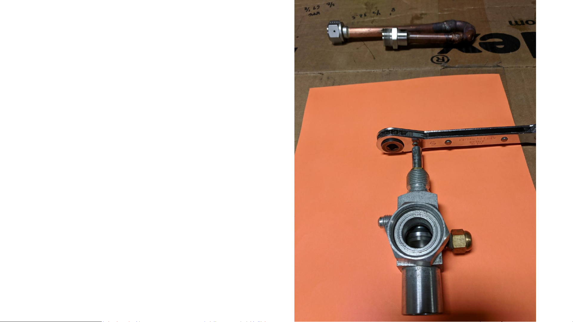
Understanding valves on the compressor
•The following terms will be used to describe the position of the 3 way compressor
service valve:
•
•Back Seated Position: Turn valve stem counter-clockwise until the valve stem is
fully extended. This closes off the service port ( the small port on the side of the
valve with the brass blank off nut).
•
•Mid Seated: From the backseat (per above) turn the valve stem three turns
clockwise. This allows refrigerant to flow to the service port. This is a common
position during servicing.
•
•Front Seated Position: Turn valve stem clockwise until fully shortened. This stops
any flow of refrigerant. THE COMPRESSOR SHOULD NOT BE RUN WITH THE VALVE
IN THIS POSITION.
•

Compressor valve
back seated
•Turn valve stem counter-clockwise
until the valve stem is fully
extended. This closes off the
service port ( the small port on the
side of the valve with the brass
blank off nut).

Compressor valve
Mid seated
•From the backseat (per above)
turn the valve stem three turns
clockwise. This allows refrigerant
to flow to the service port. This is
a common position during
servicing.

Compressor valve
front seated
•Turn valve stem clockwise until
fully shortened. This stops any
flow of refrigerant. THE
COMPRESSOR SHOULD NOT BE
RUN WITH THE VALVE IN THIS
POSITION.

Lets get started
•Step #1 Check the Cryochiller for Leaks.
•You must locate the source of leak before putting new a charge into the
Cryochiller
•
•Remove side panels to access compressor area.
•
•Leak check the full system before adjusting any valves or installing the
manifold. You don’t want to inveterately fix the leak by adjusting a valve
before you find the leak. Leak test the line and coil as well as the TVP.
Check the water side of the condenser by removing the water lines and
blowing out the water.
•

•Step #2 Connect the Manifold to the Unit
•
•Insure Manifold’s valves are closed.
•Connect the manifolds suction hose to the compressors suction service
valve.
•Connect the manifolds discharge hose to the compressor’s discharge
service valve.
•Midseat the compressors suction and discharge service valves.

Discharge valve Bitzer Comp. Suction valve Bitzer Comp. Suction valve Emerson Comp. Discharge valve Emerson Comp.

Step #3 Recover Any Remaining Refrigerant from the Unit
You may need one or two recovery cylinders depending on how much gas in the Cryochiller. Remove the cap from
the recovery cylinder’s vapor access port (the one with the blue hand valve). Evacuate each recovery cylinder
according to the cylinder manufacturer’s instructions. Follow all local and federal codes. US federal law requires
that cylinders be evacuated to 25-29 Hg vacuum.
•Connect the manifold’s center port to your charge recovery system’s inlet. Connect a recovery cylinder to the
outlet of your charge recovery system. (If the discharge side of your recovery system does not have a pressure
gauge, install a gauge between your recovery system and the cylinder.) Connect the suction side of the manifold to
the suction valve on the compressor.
•Open the valves on the manifold and on the recovery cylinder. Turn on the charge recovery system to pump the
refrigerant out of the Cryochiller.
When the recovery cylinder is filled to its rated pressure, turn off the charge recovery system. Close the valves on
the recovery system and on the recovery cylinder. Remove the full recovery cylinder and connect an empty
recovery cylinder. Continue this process until the unit is evacuated to the required level (per your local codes or to
US federal law which requires refrigerant to be recovered to 10 inches Hg vacuum.)
•Re-install the flare cap on the recovery cylinder’s vapor access port.

•Step #4 Re-Check the Cryochiller for Leaks.
•
•Connect the trace gas cylinder to the manifolds enter hose. Open both manifold valves and the
cylinder valve to pressurize the unit to 10 to 20 psig (70 –140 kPa). Close both manifold valves and
the trace gas cylinder valve. Remove the gas cylinder from the center hose.
•
• Attach the dry nitrogen to the manifold’s center hose. Open both manifold valves and the cylinder
valve and increase pressure in the unit to 250 to 350 psig.
•
•Check the entire system (including lines and in-chamber cryo coil) for leaks with the halogen leak
detector. Insure that there are no leaks anywhere in the system.
•If possible hold pressure for 24 to 48 hours to confirm system is not leaking
•Closing hand valves on front of unit, the Cryochiller can be isolated from the coil output side. Doing
this can help confirm if the leak is in the Cryochiller or the attached line set(s) and coil(s).
•

•Step #5 Evacuate the Cryochiller.
•
•Turn on the unit and allow the compressor to run for 30 seconds.
• Remove the dry nitrogen connection from the manifold’s center hose.
Release the vapors/gasses from the unit by opening both manifold
valves.
•
• Connect the vacuum pump to the manifold’s center hose and turn on the
pump. Evacuate the system to at least 2.5 inches Hg vacuum (17 kPa).
Continue pumping for another 30 minutes. Upon finishing, close both
manifold valves.

•Evacuate the unit for a second time
•
• Connect the dry nitrogen to the manifold’s center hose. Open the
manifold’s suction valve and pressurize to 100 – 120 psig. Turn on the
unit and allow the compressor to run for 30 seconds.
• Remove the dry nitrogen connection from the manifold’s center hose.
Release the vapors/gasses from the unit by opening both manifold
valves.
•
• Connect the vacuum pump to the manifold’s center hose and turn on the
pump. Evacuate the system to at least 0.1 Torr or 100 microns (13 Pa)
to insure it is completely clean and dry. Use caution to prevent any
contaminants from entering the system while connecting or
disconnecting any part of the unit or manifold.


•The full gas charge
can come in
disposable cylinders
or in a reusable
cylinder.
•Depending on your
countries laws and
what Cryochiller
model you have this
can be from 1 to 3
tanks for a full gas
charge.
Re-fillable cylinder 1 per chargeDisposable cylinders 2-3 per charge

•Step #6 Recharge the Cryochiller
•
• Insure manifold’s valves are closed. Insure the compressor’s suction and discharge valves are in the midseated
position.
• Connect tank #1 of the replacement refrigerant charge to the manifold’s center hose.
• Purge the manifold’s center hose of air: loosen the hose where it connects to the manifold; slightly open the
cylinder’s valve for no more than 1 to 2 seconds; then immediately tighten the hose at the manifold.
•Open the cylinder valve. Turn the cylinder upside down so that the liquid refrigerant will be drawn into the unit
first. If using a refillable tank connect to the liquid side of the gas cylinder.
• Open the manifold’s discharge valve. Wait for the pressure to equalize (suction and discharge gauge’s would
show the same pressure). The pressures should equalize within 2 minutes.
• Close the manifold’s discharge valve.
•Repeat steps 1 –6 for Tank #2 and Tank #3 of the replacement refrigerant charge if applicable.
•
•You will need to draw the remaining gas out of the cylinders. This can be accomplished one of the following
ways:
•

Charging with disposable tank using recovery
pump
Table of contents
Other Telemark Chiller manuals
Popular Chiller manuals by other brands

SMC Networks
SMC Networks HRS012-A*-10-* Operation manual

SMC Networks
SMC Networks AMS20 Operation manual

York
York YK Style H Operation manual

Elkay
Elkay ERS1-1D Installation, care & use manual

Carrier
Carrier AQUASNAP 30RBM Series Installation, operation and maintenance instructions

Stirling
Stirling STR-HVBF quick start guide

Daikin
Daikin EWAQ080DAYN Operation manual

Carrier
Carrier AquaEdge 19XR series Start-up, operation and maintenance instructions

Advantage Engineering
Advantage Engineering Maximum instruction manual

Daikin
Daikin Clima-Flex IOM CLIM Series Installation, operation and maintenance manual

MTA
MTA Aries AS 251 FC manual

Carrier
Carrier 30MP-900---036 installation instructions