Eurolube 53417 User manual

www.eurolube.com EUROLUBE EQUIPMENT AB
PART NO 53417
ANALOGUE LEVEL SENSOR
INSTALLATION GUIDE
2010-02
1
General
The four analogue inputs on the TCM supports any standard industrial 2-lead /
4-20mA / 24VDC sensors. To connect sensors a 2-pole connector is used.
The submergeable pressure based level sensor 53417 is a robust sensor that can
be used with good accuracy for tanks with a height of 1 – 5 meters. Max height
depends on density of fluid. The measuring resolution for a TCM with a 53417
sensor is 4 mm for water and about 4.5 mm for mineral oil.
MECHANICAL INSTALLATION
Connect the red wire to +24VDC and the black wire to Sense. +24VDC and Sense are printed on the PCB. If the
sensor cable (6.5 m) is too short to reach the TCM it can be lengthened using a standard 2-lead wire with copper
area of 0.5 mm2 for each lead. For this purpose use the by-packed connection box. It is not necessary to use the
shield to obtain a good signal because the signal is current based. The shield can be used for protection grounding
purposes if needed.
Observe! – It is important that the transparent tube is not blocked. You must always connect the level sensor to
the connection box and a standard 2-lead signal cabling.
NOTE! THE METERRANGE VALUE MAY NEED TO BE CHANGED DEPENDING ON LEVEL SENSOR
SENSITIVITY.
Connection box
Breathing tube
Shield (not used)
+24V
Sol
A
B
GND
+24V
4-20mA
Solenoid valve
Should be bridged
when not in use!
RED = +24V
BLUE = 4-20mA
TCM
Level sensor
53417
Tank full Tank half full Tank empty

www.eurolube.com
EUROLUBE EQUIPMENT AB
PART NO 53417
ANALOGUE LEVEL SENSOR
2
www.eurolube.com
Some general information about the sensor technology that we’re using:
The 4-20mA current loop is a common method of transmitting sensor information in many industrial process-monitoring applications. A sensor
is a device used to measure physical parameters such as temperature, pressure, speed, liquid fl ow rates, etc. Transmitting sensor information
via a current loop is particularly useful when the information has to be sent to a remote location over long distances (1000 feet, or more). The
loop’s operation is straightforward: a sensor’s output voltage is fi rst converted to a proportional current, with 4mA normally representing the
sensor’s zero-level output, and 20mA representing the sensor’s full-scale output. Then, a receiver at the remote end converts the 4-20mA
current back into a voltage which in turn can be further processed by a computer or display module.
Installing the sensor consists of a few steps. They can be a bit complicated if you are not used to handling the system.
Read these steps before doing anything!
Connect the sensor as described in the first page.1.
Ensure that the breathing tube is exiting in the sealed connection box with hygroscopic filter. En-
sure that the indicator on the circuit board lights up when the sensor is connected. Do not put the
sensor in the tank yet!
Adjusting the meter range2.
Depeding on what sensor you have in your hand, an adjustment might be needed. Different suppliers of these sensors have dif-
ferent meter ranges. The sensor we used when we first introduced this system has a meter range of 0.400. This is why this is the
default value in the software. We have now in stock sensors that has both 0.400 and 0.500. This needs to be changed in the tank
module depending on which sensor you’ve got. For example, if the sensor is labelled “RANGE 0~5mH2O” it means it needs to be
changed to 0.500.
Do this by right-clicking the sensor in the Neighborhood and choosing Properties. At the bottom
of the window is a value called MeterRange. Change this to reflect the sensor you are currently
using. Repeat for all sensors.
Calibrating the zero level of the sensor.3.
There are two ways to do this, either using the PC (slow process, not very accurate) or, from the keypad (faster, somewhat more
robust). We strongly recommend using the keypad. Start by hanging the sensor outside the tank in the same height as the bottom
of the tank.
Using the PC3.1.
Look at the symbol in Neighborhood and see how many percent it shows in the tank when the sensor is outside the tank. Right-
click and choose Properties, then adjust the value Zero Offset. For example, if the sensor is showing 5%, type Zero Offset -0.1 to
decrease the reading and wait 1-2 minutes and observe the change in the sensor symbol. Repeat until it shows as close to 0% as
possible. However, the update frequency on the PC makes this a slow process and not very accurate.
Using the keypad3.2.
Start by going into the SETUP-meny on any keypad in the system. (Type SETUP followed by Enter,
then the password and then Enter).
In order to calibrate the sensor, we need to know how much the sensor is differing from the normal
value (4.00mA). We are now going to view the sensor reading in real time, from the tank module by
using what we call a “Fast Menu” code. Do this by typing at the Adress promt:
XXXX0Y61
Where XXXX = the address of the tank module and Y = the port# in the tank module. So if you for
example want to view port 2 on tank module 8002 you would type:
You will now see the current sensor signal in mA, something like this:
This tells us that the sensor is showing a little too much and we need to adjust it DOWN.
If the sensor is showing “Sensor out of scale”, it means that we need to adjust it UP.
Indicates when
sensor is present.
(Sensor connects here)
I=4.12mA 0.5%
*** CH2 Signal**
Addr:80020261
Address[CODE]
Reel:SETUP ‡
EXIT STOP CE ENT
PASS:_ ‡
Enter password

www.eurolube.com
ANALOGUE LEVEL SENSOR
www.eurolube.com EUROLUBE EQUIPMENT AB
PART NO 53417
ANALOGUE LEVEL SENSOR
3
Exit the sensor signal viewer by pressing EXIT once. Enter the setup configuration of the tank
module by typing the module’s adress followed by Enter.
You will now see the main menu of the tank module, like this:
Press the down arrow to scroll to the port you are calibrating
Press Enter. Press the down arrow to the value “Zero adjust”
For example, if the sensor value is 4.12, input -0.12. Press Enter, then CE to clear the field and
input the new value. To type a “-” sign, press twice on the down arrow on the keypad and then the
“?” button.
Press Enter to save the new value. Go back and check the sensor reading to make sure that it’s
now showing 4.00mA.
Repeat for all sensors.
Inputting the rest of the settings (except TankArea).4.
Using the Neighborhood, right click on the sensor symbol and select Properties.
SETTING EXPLANATION
TankNo: Is not really used by the system but is good to fill in properly as information.
Mask: Not used when an analogue sensor is connected. However, if you are not using a discrete level
sensor (float sensor), you must either A) bridge the connection between A-GND and B-GND or B)
check the boxes “Invert A” and “Invert B”.
Time(t): Sets the time interval for the integrated mean value calculation. A low value will result in faster
update but a more turbulent value Higher value will give a slower update but a more stable value.
Default is “6” witch will give about 30 s update interval.
Zero Offset: This value is used to set the level reading to zero when when the tank is empty. If you have fol-
lowed the steps above, do not modify this!
Span Gain: This value can be used to fine tune the amplification, (adjust so that the reading gives the correct
value with a full tank), when all other parameters are set. The default value is 1.000 and should
normally be that.
Density: Sets the density of the fluid that is in the tank at the normal temperature. It is 1,000 for water at
20°C. A good estimation for mineral oil is 0,875 at 20°C.
MaxVolume: This value is not necessary but must be set to have a correct % statement for the quick status
window in graphic layouts.
LED Address: This can be used to use a LED display for remote reading of the tank level. OBSERVE that if this is
set that LED will be unavailable for showing dispensing!
Fluid Name: This value is not necessary but should be set to the same value as in WinDB Manager.
FluidPartNo: This value is not necessary but should be set to the same value as in WinDB Manager.
MeterRange: This value specifies the measuring range for the used level sensor.
Note! The meterrange value may need to be changed depending on level sensor sensitivity. Range
0~5mh2o means 0.500 as meter range
Addr:8???_ ‡
Address[CODE]
TCM: ‡
TCM MainMenu
PortX: ‡
TCM MainMenu
O: 0.000 ‡
Zero adjust
O: -0.12 ‡
Zero adjust
I= 4.00mA 0.0%
*** CH2 Signal**

EUROLUBE EQUIPMENT AB
Stråssavägen 2, SE-711 76 Storå, Sweden
EMAIL eurolube@eurolube.com PHONE +46 581 836 65 FAX +46 581 409 75
www.eurolube.com
PART NO 53417
ANALOGUE LEVEL SENSOR
4
Connection box
Breathing tube
Shield (not used)
+24V
Sol
A
B
GND
+24V
4-20mA
Solenoid valve
Should be bridged
when not in use!
RED = +24V
BLUE = 4-20mA
TCM
Level sensor
53417
Tank full Tank half full Tank empty
Analogue level sensor symbol
The analogue sensor symbol shows graphically in real-time the current volume of the tank.
Setting the tank Area5.
Now, set the tank area. The tank area is calculated using all the fields above so make sure you do this
last, or do it again when you’ve made a modification to the parameters!
For example, if the tank is 1,5 x 2,5 meters, input 3,75 as the Tank Area and click Generate. Press the
OK-button when it is done.
Inserting the sensor6.
You can now insert the sensor into the tank. Make sure that the sensor touches the bottom of the tank.
The basic installation of the sensor is now complete! However, in order for the tank module to open the solenoid valve for com-
pressed air for the pump when someone is dispensing fluid, one additional setting is needed:
Tank Settings in LUBE-Master WinTools7.
WinDB Manager7.1.
Go to Management, Tanks.
For each tank, input the values for each tank.
Tank type: If the tank is fresh oil and no other sensor
than the analogue, input “001”.
TCM Address: The address for the tank module.
TCM Port: The port which the sensor is connected to.
Valve delay: The valve delay value can be used if you would like the port to stay open for a little while to let the pump build up
pressure in the pipe system, to minimize the delay when the next person is going to dispense fluid.
Engine7.2.
Restart the Engine to complete the process.
If it does not work, look in the C:\Lubemast\Logs\WinDB.log file for errors.
8000 1
Table of contents
Popular Accessories manuals by other brands

Nuaire Group
Nuaire Group CO2RM installation guide
Honeywell
Honeywell H7012A Mounting instructions
JVC
JVC Multi-Format SDI Unit IF-C151HDG instructions
Pablo
Pablo circa Assembly/installation instructions

SPX
SPX Marley LW032 B Series user manual
Honeywell Home
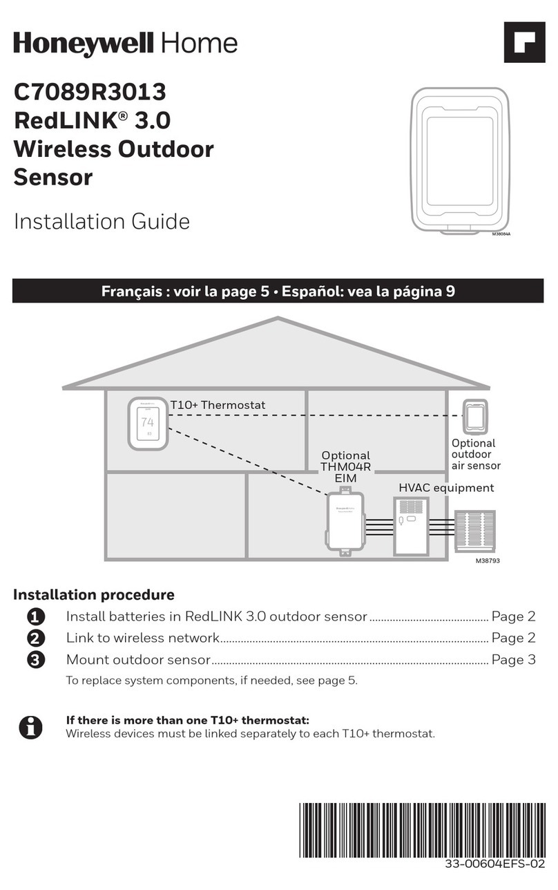
Honeywell Home RedLINK C7089R3013 installation guide
