Eurotech An0067 User manual

Rev. 2.0 - December 2007 - ETH_An0067_USM20-2007- 12
An006
7
Cable-set Reference Guide

2 Introduction
Disclaimer
The information in this manual has been carefully checked and is believed to be accurate. Eurotech assumes no
responsibility for any infringements of patents or other rights of third parties, which may result from its use.
Eurotech assumes no responsibility for any inaccuracies that may be contained in this document. Eurotech makes no
commitment to update or keep current the information contained in this manual.
Eurotech reserves the right to make improvements to this document and/or product at any time and without notice.
Warranty
This product is supplied with a limited warranty. The product warranty covers failure of any Eurotech manufactured
product caused by manufacturing defects. Eurotech will make all reasonable effort to repair the product or replace it with
an equivalent alternative. Eurotech reserves the right to replace the returned product with an alternative variant or an
equivalent fit, form and functional product. Delivery charges will apply to all returned products.
Trademarks
All trademarks, both marked and not marked, appearing in this document are the property of their respective owners.
WEEE
The information below is issued in compliance with the regulations as set out in the 2002/96/CE directive, subsequently
superseded by 2003/108/CE. It refers electrical and electronic equipment and the waste management of such products.
When disposing of a device, including all of its components, subassemblies and materials that are an integral part of the
product, you should consider the WEEE directive.
This symbol has been attached to the equipment or, if this has not been possible, on the packaging,
instruction literature and/or the guarantee sheet. By using this symbol, it states that the device has been
marketed after August 13th 2005, and implies that you must separate all of its components when possible,
and dispose of them in accordance with local waste disposal legislations.
Because of the substances present in the equipment, improper use or disposal of the refuse can cause
damage to human health and to the environment.
With reference to WEEE, it is compulsory not dispose of the equipment with normal urban refuse,
arrangements should be instigated for separate collection and disposal.
Contact your local waste collection body for more detailed recycling information.
In case of illicit disposal, sanctions will be levied on transgressors.
RoHS
This device, including all it components, subassemblies and the consumable materials that are an integral part of the
product, has been manufactured in compliance with the European directive 2002/95/EC known as the RoHS directive
(Restrictions on the use of certain Hazardous Substances). This directive targets the reduction of certain hazardous
substances previously used in electrical and electronic equipment (EEE).
Related Documentation
For further information please refer to the appropriate User manual for the CPU or Peripheral that you are using the
adaptor with.
© 2007 Eurotech Spa
Eurotech S.p.A.
A member of the Eurotech Group
Via Fratelli Solari, 3/a
33020 - AMARO (UD)
ITALY
An0067 Cable-set Reference Guide

Introduction 3
Introduction
Manual Conventions
The following conventions are used throughout this manual.
The “Mode” of the register:
Symbol / Text Definition
RW Readable and Writable register
RO Read only register
W Meaning of the register when written
R Meaning of the register when read
Hexadecimal numbering:
Hexadecimal numbers are indicated with an “h” suffix (for example: 11Ch)
Symbols and Text used in Pin-out tables:
Symbol / Text Definition
◄Input
►Output
◄► Bi-Directional
▬Passive
Module
specific Dependent on module installed
NC Not Connected
Reserved Use reserved to Eurotech, must remain unconnected
# Active low signal
Warnings and Important Notices:
Within this manual you will find the following tables, please ensure that you read and understand these as
they are intended to highlight potential risks or precautions that should be taken.
Warnings:
Information to alert you to potential hazards:
Potential personal injury or damage to a system, device or program.
Information notes:
Indicates important features or instructions that should be observed
An0067 Cable-set Reference Guide

4 Introduction
Technical Assistance
If you have any technical questions or if you cannot isolate a problem with your device, please e-mail the
Eurotech Technical Support Team: email: techsupp@eurotech.it
RMA Requests
Before returning any Eurotech product, for any reason, you must e-mail the Eurotech Technical Support
Team on the above email address, giving the following information; you will then be sent an RMA number
(Returned Material Authorization) for the return of the material:
Model number (see Figure 1)
Serial number (see Figure 1)
Detailed fault description
Company Details
Contact details
Transportation
When transporting any module or system, for any reason, it should be packed using anti-static material and
placed in a sturdy box with enough packing material to adequately cushion it.
Warnings:
Any product returned to Eurotech that is damaged due to inappropriate packaging will
not be covered by the warranty!
Board labelling
On the external side of the ISA Bus connector, you will find several labels displaying the following:
• Batch Number
• Serial Number
• Model Number
• Hardware Revision
Note:
The actual location of these labels may vary depending on the product purchased.
For example: If no ISA bus is present, the PCI bus may be used instead.
However, the labelling formats will remain the same.
Model Number Hardware Revision
Serial Number
Batch Number
Figure 1. Board label locations
An0067 Cable-set Reference Guide

Table of Contents
Introduction...................................................................................................................................................... 3
Manual Conventions.......................................................................................................................................... 3
Technical Assistance......................................................................................................................................... 4
RMA Requests................................................................................................................................................... 4
Transportation.................................................................................................................................................... 4
Board labelling................................................................................................................................................... 4
Table of Contents ............................................................................................................................................ 5
Chapter 1 Cable-set Components.............................................................................................................. 7
CBL-1212-00 ..................................................................................................................................................... 8
Kit Contents ............................................................................................................................................................. 8
Connector Layout..................................................................................................................................................... 8
CBL-1213-00 ..................................................................................................................................................... 9
Kit Contents ............................................................................................................................................................. 9
Connector Layout..................................................................................................................................................... 9
CBL-1421-00 ................................................................................................................................................... 10
Kit Contents ........................................................................................................................................................... 10
Connector Layout................................................................................................................................................... 10
CBL-1452-00 ................................................................................................................................................... 11
Kit Contents ........................................................................................................................................................... 11
Connector Layout................................................................................................................................................... 11
CBL-1454-00 ................................................................................................................................................... 12
Kit Contents ........................................................................................................................................................... 12
Connector Layout................................................................................................................................................... 12
Chapter 2 Cable Descriptions .................................................................................................................. 13
7000000004L: IDE Cable ................................................................................................................................ 14
7000000030L: Single COM Port...................................................................................................................... 15
7000000031L: Single Parallel Port.................................................................................................................. 16
7000000032L: Two Serial ports....................................................................................................................... 17
7000000045L: IDE Interface............................................................................................................................ 18
7000000074L: Two COM Ports....................................................................................................................... 19
7000000091L: CPU module to Multifunction Adaptor..................................................................................... 20
7000000124L: Multifunction, Mouse and VGA Output.................................................................................... 21
7020000010L: Auxiliary Power........................................................................................................................ 22
7020000011L: Auxiliary Power........................................................................................................................ 23
7030000081L: 1 Parallel Port and 2 Serial Ports............................................................................................ 24
7030000083L: CPU to Timers, 2 Serial Ports and Ethernet Adaptor.............................................................. 26

(This page is intentionally left blank.)

Chapter 1 Cable-set Components
This Chapter lists each Cable-set and all the Components that the customer will receive with each set

8 Cable-set Components
An0067 Cable-set Reference Guide
CBL-1212-00
Revision Date
Cable-set Part Number For use with Cable-set Revision Date
CBL-1212-00 CPU-1212 25/07/2006
Kit Contents
Eurotech
Part #
Qty. Connector. Type Description RoHS Page
7000000004L 1 J4 Cable IDE Interface 914
7000000030L 2 J1 or J2 Cable COM1 or COM2 915
7000000031L 1 J3 Cable Parallel 916
7000000091L 1 J6 Cable Multifunction Adaptor 920
7020000010L 1 J9 Cable Auxiliary Power 922
9C630600S6L 1 -- Adaptor Multifunction Adaptor 9
Connector Layout

Cable-set Components 9
An0067 Cable-set Reference Guide
CBL-1213-00
Revision Date
Cable-set Part Number For use with Cable-set Revision Date
CBL-1213-00 CPU-1213 25/07/2006
Kit Contents
Eurotech
Part #
Qty. Conn. Type Description RoHS Page
7000000030L 2 J5 & J6 Cable COM1 & COM2 915
7000000031L 1 J4 Cable Parallel 916
7000000032L 1 J10 & J11 Cable COM3 & COM4 917
7000000045L 1 J9 Cable IDE Hard Drive 918
7000000091L 1 J3 Cable CPU to Multifunction Adaptor 920
7020000011L 1 J13 Cable Auxiliary Power 923
9C630600S6L 1 -- Adaptor Multifunction Adaptor 9
Connector Layout
10 Cable-set Components
An0067 Cable-set Reference Guide
CBL-1421-00
Revision Date
Cable-set Part Number For use with Cable-set Revision Date
CBL-1421-00 CPU-1421 25/07/2006
Kit Contents
Eurotech
Part #
Qty. Conn. Type Description RoHS Page
7000000045L 1 J7 Cable IDE 918
7000000124L 1 J6 Cable Multifunction 921
7020000011L 1 J8 Cable Auxiliary Power 923
7030000081L 1 J4 Cable COM3, COM4 and Parallel 924
7030000083L 1 J5 Cable COM1, COM2, Ethernet 2 & Timers 926
9C630600S6L 1 -- Adaptor Multifunction 9
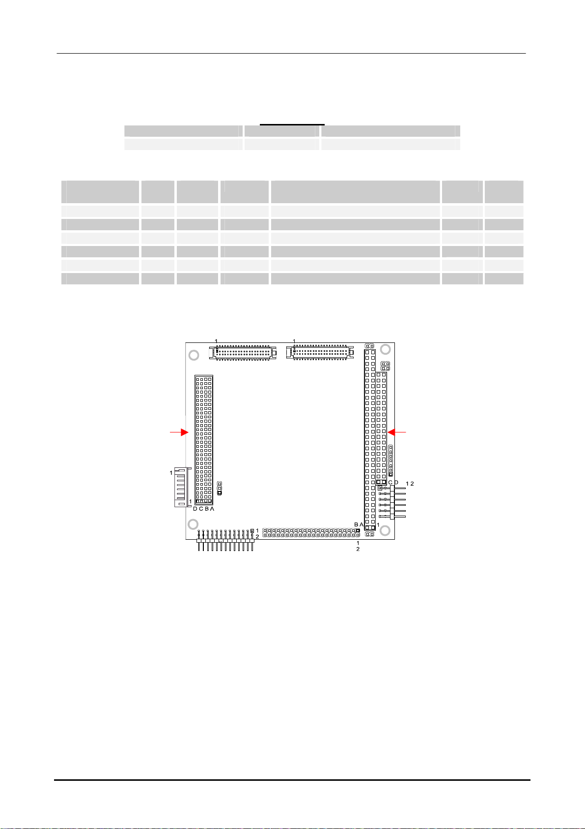
Connector Layout
J5 J4
J8
J1, J2
J3
J12
J9
J7
J6

Cable-set Components 11
An0067 Cable-set Reference Guide
CBL-1452-00
Revision Date
Cable-set Part Number For use with Cable-set Revision Date
CBL-1452-00 CPU-1452
CPU-1462 25/07/2006
Kit Contents
Eurotech
Part #
Qty. Conn. Type Description RoHS Page
7000000045L 1 J5 Cable IDE 918
7000000074L 1 J17 Cable COM1 & COM2 919
7000000124L 1 J4 Cable Multifunction & VGA 921
7020000011L 1 J9 Cable Auxiliary Power 923
9C630600S6L 1 -- Adaptor Multifunction 9
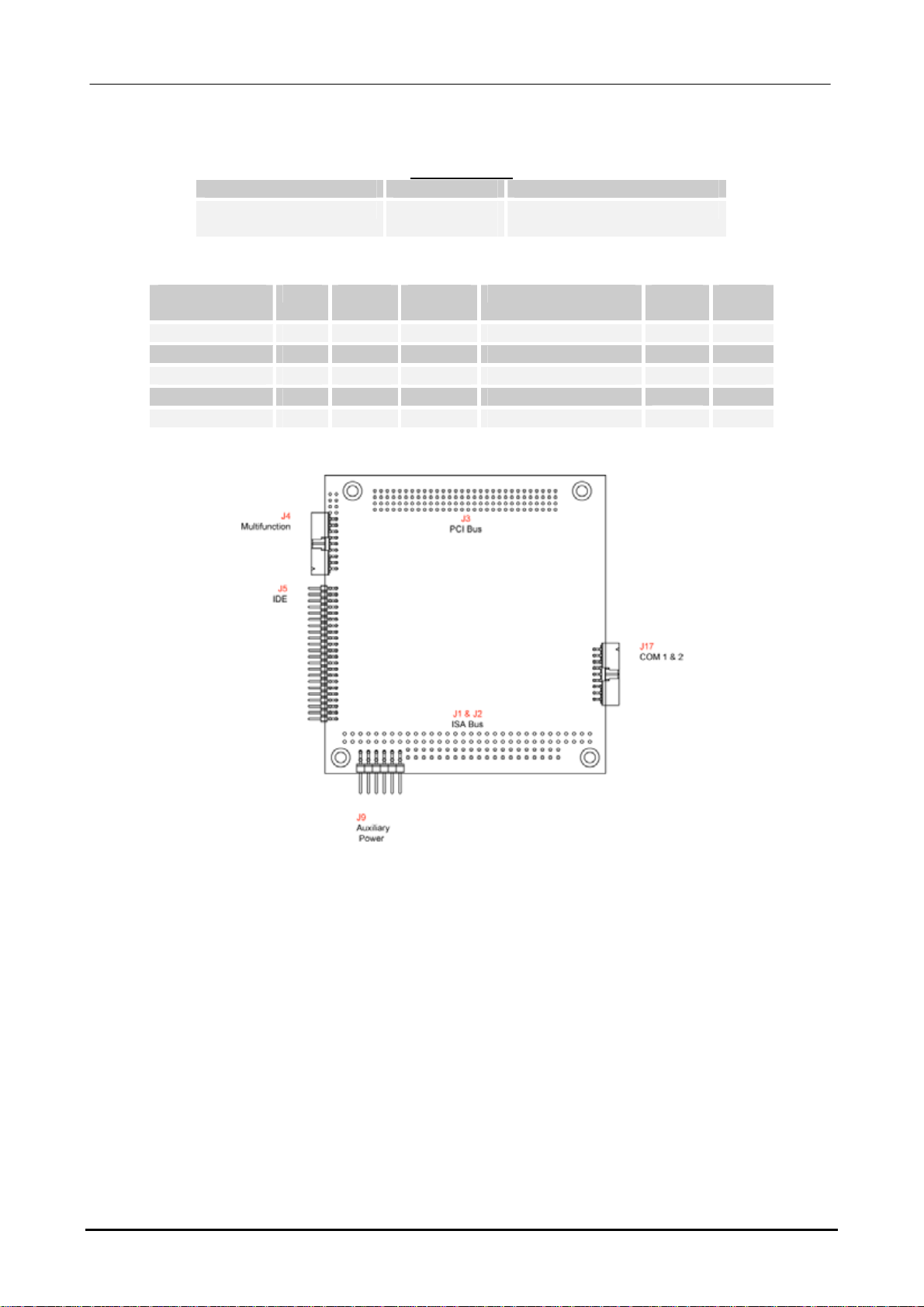
Connector Layout
12 Cable-set Components
An0067 Cable-set Reference Guide
CBL-1454-00
Revision Date
Cable-set Part Number For use with Cable-set Revision Date
CBL-1454-00 CPU-1454
CPU-1464 25/07/2006
Kit Contents
Eurotech
Part #
Qty. Conn. Type Description RoHS Page
7000000045L 1 J5 Cable IDE 918
7000000074L 1 J17 Cable COM1 & COM2 919
7000000124L 1 J4 Cable Multifunction & VGA 921
7020000011L 1 J9 Cable Auxiliary Power 923
9C630600S6L 1 -- Adaptor Multifunction 9
Connector Layout

Chapter 2 Cable Descriptions
This Chapter gives detailed descriptions of all the cables supplied

14 Cable Descriptions
7000000004L: IDE Cable
For use with:
CPU-1212
Connectors
Connector # Type Pins Format Pitch (mm)
Cn1 Minitek IDE 40 20x2 2.54
Cn2 Minitek IDE 40 20x2 2.54
Pinout
Cn1 Cn2 Usage Cn1 Cn2 Usage
1 1 PWG 2 2 Ground
3 3 ID7 4 4 ID8
5 5 ID6 6 6 ID9
7 7 ID5 8 8 ID10
9 9 ID4 10 10 ID11
11 11 ID3 12 12 ID12
13 13 ID2 14 14 ID13
15 15 ID1 16 16 ID14
17 17 ID0 18 18 ID15
19 19 Ground 20 20 Not Used
21 21 Not Used 22 22 Ground
23 23 BIOW# 24 24 Ground
25 25 BIOR# 26 26 Ground
27 27 IOCHRDY# 28 28 Sync / CSEL
29 29 DMACK# 30 30 Ground
31 31 IRQ 32 32 IOCS16#
33 33 SA1 34 34 PDIAG#
35 35 SA0 36 36 SA2
37 37 CSO# 38 38 CS1#
39 39 DASP# / LED 40 40 Ground
An0067 Cable-set Reference Guide
Cable Descriptions 15
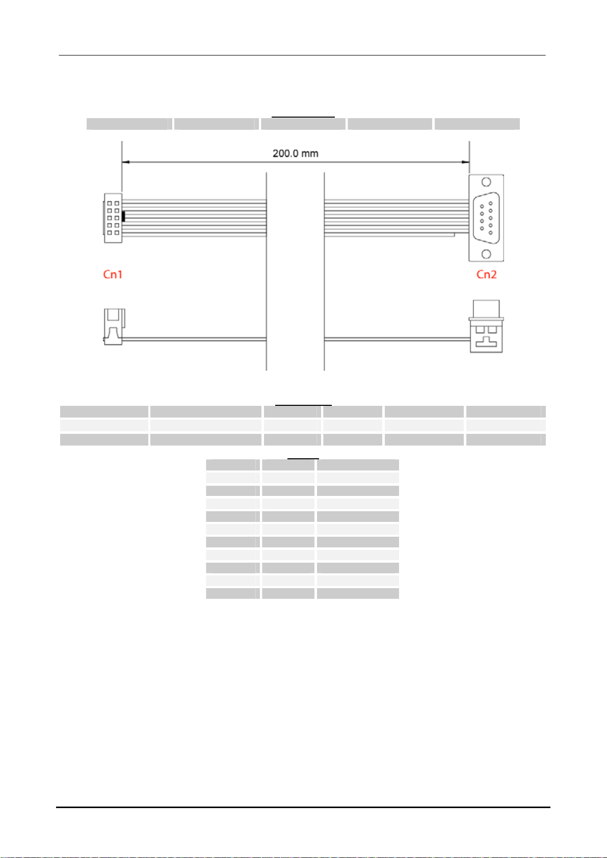
7000000030L: Single COM Port
For use with:
CPU-1212 CPU-1213
Connectors
Connector # Type Pins Format Pitch (mm) Wire Type
Cn1 Female IDC 10 5x2 2.54 AWG28
Cn2 Male DB9 9 DB9 -- AWG28
Pinout
Cn1 Pin Cn2 Pin Usage
1 1 DCD
2 6 DSR
3 2 RX
4 7 RTS
5 3 TX
6 8 CTS
7 4 DTR
8 9 RI
9 5 Ground
10 -- Not Connected
An0067 Cable-set Reference Guide

16 Cable Descriptions
7000000031L: Single Parallel Port
For use with:
CPU-1212 CPU-1213
Connectors
Connector # Type Pins Format Pitch (mm) Wire Type
Cn1 Female IDC 26 13x2 2.54 AWG28
Cn2 Female DB25 25 DB25 -- AWG28
Pinout
Cn1 Cn2 Usage Cn1 Cn2 Usage
1 1 -Strobe 2 14 -Auto Feed
3 2 +Data Bit 0 4 15 -Error / Fault
5 3 +Data Bit 1 6 16 -Printer Initiate
7 4 +Data Bit 2 8 17 -Select
9 5 +Data Bit 3 10 18 Ground
11 6 +Data Bit 4 12 19 Ground
13 7 +Data Bit 5 14 20 Ground
15 8 +Data Bit 6 16 21 Ground
17 9 +Data Bit 7 18 22 Ground
19 10 -Acknowledge 20 23 Ground
21 11 +Busy 22 24 Ground
23 12 + Paper End 24 25 Ground
25 13 +Select 26 -- Not Connected
An0067 Cable-set Reference Guide

Cable Descriptions 17
7000000032L: Two Serial ports
Applies to
CPU-1213
Connectors
Connector # Type Pins Format Pitch (mm)
Cn1 Female IDC 20 2x10 2.54
Cn2, Cn3 Male DB9 9 DB9 --
Pinout
Cn1 Conn. Pin # Usage Cn1 Conn Pin # Usage
1 Cn2 1 DCD 2 Cn2 6 DSR
3 Cn2 2 RX 4 Cn2 7 RTS
5 Cn2 3 TX 6 Cn2 8 CTS
7 Cn2 4 DTR 8 Cn2 9 RI
9 Cn2 5 Ground 10 Cn2 -- Not Connected
11 Cn3 1 DCD 12 Cn3 6 DSR
13 Cn3 2 RX 14 Cn3 7 RTS
15 Cn3 3 TX 16 Cn3 8 CTS
17 Cn3 4 DTR 18 Cn3 9 RI
19 Cn3 5 Ground 20 Cn3 -- Not Connected
An0067 Cable-set Reference Guide

18 Cable Descriptions
7000000045L: IDE Interface
For use with:
CPU-1213 CPU-1421 CPU-1452
CPU-1462 CPU-1454 CPU-1464
Connectors
Connector # Type Pins Format Pitch (mm)
Cn1 Minitek 44 22x2 2.00
Cn2, Cn3 IDC 40 20x2 2.54
Pinout
Cn1 Cn2 / Cn3 Usage Cn1 Cn2 / Cn3 Usage
1 1 /Reset 2 2 Ground
3 3 Data 7 4 4 Data 8
5 5 Data 6 6 6 Data 9
7 7 Data 5 8 8 Data 10
9 9 Data 4 10 10 Data 11
11 11 Data 3 12 12 Data 12
13 13 Data 2 14 14 Data 13
15 15 Data 1 16 16 Data 14
17 17 Data 0 18 18 Data 15
19 19 Ground 20 20 Key
21 21 Not Used 22 22 Ground
23 23 /IOW 24 24 Ground
25 25 /IOR 26 26 Ground
27 27 IO_CH_RDY 28 28 ALE
29 29 Not Connected 30 30 Ground
31 31 IRQR 32 32 /IOCS16
33 33 Address 1 34 34 Not Connected
35 35 Address 0 36 36 Address 2
37 37 /IDE_CS0 38 38 /IDE_CS1
39 39 /ACTIVE 40 40 Ground
An0067 Cable-set Reference Guide

Cable Descriptions 19
7000000074L: Two COM Ports
For use with:
CPU-1452 CPU-1462 CPU-1454 CPU-1464
Connectors
Connector # Type Pins Format Pitch (mm)
Cn1 Minitek IDC 18 9x2 2.00
Cn2 / Cn3 D-Sub 9 9 DB9 --
Pinout
Cn1 Conn. Pin # Usage Cn1 Conn. Pin # Usage
1 Cn2 1 Carrier Detect 2 Cn2 6 Data Set Ready
3 Cn2 2 Receive Data 4 Cn2 7 Request To Send
5 Cn2 3 Transmit Data 6 Cn2 8 Clear To Send
7 Cn2 4 Data Terminal Ready 8 Cn2 9 Ring Indicator
9 Cn2 5 Ground 10 Cn3 1 Carrier Detect
11 Cn3 6 Data Set Ready 12 Cn3 2 Receive Data
13 Cn3 7 Request To Send 14 Cn3 3 Transmit Data
15 Cn3 8 Clear To Send 16 Cn3 4 Data Terminal Ready
17 Cn3 9 Ring Indicator 18 Cn3 5 Ground
An0067 Cable-set Reference Guide

20 Cable Descriptions
7000000091L: CPU module to Multifunction Adaptor
For use with:
CPU-1212 CPU-1213
Connectors
Connector # Type Pins Format Pitch (mm)
Cn1 Minitek IDC 10 5x2 2.54
Cn2 Minitek IDC 10 5x2 2.54
Pinout
Cn1 Cn2 Usage Cn1 Cn2 Usage
1 1 Speaker 2 2 +5V
3 3 Reset 4 4 WDTL
5 5 Keyboard Data 6 6 Keyboard Clock
7 7 Ground 8 8 +5V
9 9 VBAT 10 10 VPP
An0067 Cable-set Reference Guide
Table of contents


