Vahle KBSL User manual

Montageanleitung - Wartung
KBSL • KSL • KSLT
Mounting instructions - Maintenance
KBSL • KSL • KSLT

KBSL • KSL • KSLT
2
Montageanleitung •Mounting instructions
Inhaltsverzeichnis
Sicherheitshinweise . . . . . . . . . . . . 3
Warnhinweise und Symbole . . . . 3
Qualifikation des Personals . . . . 3
Transport und Lagerung . . . . . . . . . 4
Verlegungsplan . . . . . . . . . . . . . . . . 4
Halteeisen anbringen . . . . . . . . . . . 5
Schleifleitung aufhängen . . . . . . . . 5
Schleifleitung ausrichten . . . . . . . . 6
Stromschienen- und Gehäuse-
verbindungen für KBSL, KSL, KSLT 6
a) Schleifleitung mit
Feder-Steckverbindern . . . . . . 6
b) Schleifleitung mit Schraub-
verbindern . . . . . . . . . . . . . . . . . 7
Verbindungsstellen glätten . . . . . 7
Gehäuseverbindungen und
Endkappen . . . . . . . . . . . . . . . . . . . 7
Stromabnehmer einsetzen . . . . . . . 7
Kontrollen . . . . . . . . . . . . . . . . . . . . 8
Mechanische und elektrische
Verbindungen . . . . . . . . . . . . . . . . . 8
Kopfeinspeisung . . . . . . . . . . . . . . . 9
Streckeneinspeisung . . . . . . . . . . . 9
Überleitungseinführung . . . . . . . . 10
Einführungstrichter . . . . . . . . . . . . 11
Ausbauteilstück . . . . . . . . . . . . . . 12
Dehnungsteilstück . . . . . . . . . . . . 13
Belüftungsteilstück . . . . . . . . . . . . 14
Dichtlippe „D“ (bei KSLT) . . . . . . . 14
Schlitzabdeckungen „FP“
(bei KSLT) . . . . . . . . . . . . . . . . . . . . 15
KTW-System mit
KBSL, KSL und KSLT . . . . . . . . . . 16
Aufhängewinkel montieren . . . . 16
Schleifleitung montieren . . . . . . 17
Tragschiene montieren . . . . . . . 17
Stromabnehmern und
Tragwageneinsetzen . . . . . . . . . .17
Pufferanschlag PS 2 und
Endkappe K 40 montieren . . . . .17
Wartung . . . . . . . . . . . . . . . . . . . . . 18
Schleifleitung . . . . . . . . . . . . . . . 18
Stromabnehmer . . . . . . . . . . . . . 18
Table of content
Safety Instructions . . . . . . . . . . . . . 3
Warnings and Symbols . . . . . . . . 3
Personnel qualifications . . . . . . . 3
Transport and Storage . . . . . . . . . . 4
Installation drawing . . . . . . . . . . . . 4
Mounting of support brackets . . . . 5
Installation of powerail . . . . . . . . . . 5
Alignment of the powerail . . . . . . . 6
Powerail and housing joints
for KBSL, KSL, KSLT . . . . . . . . . . . . 6
a) powerail with plug-in-joints . . 6
b) powerail with bolted joints . . . 7
Smoothing the joints . . . . . . . . . . 7
Housing joints and end caps . . . . . 7
Insertion of current collector . . . . . 7
Inspections . . . . . . . . . . . . . . . . . . . 8
Mechanical and electrical
connections . . . . . . . . . . . . . . . . . . . 8
End feed . . . . . . . . . . . . . . . . . . . . . . 9
Line feed . . . . . . . . . . . . . . . . . . . . . 9
Transfer guide . . . . . . . . . . . . . . . .10
Transfer funnel . . . . . . . . . . . . . . . .11
Removing section . . . . . . . . . . . . . 12
Expansion section . . . . . . . . . . . . .13
Anti Condensation section . . . . . . 14
Neoprene sealing
strip “D” (for KSLT) . . . . . . . . . . . . 14
Shieldind „FP“ (for KSLT) . . . . . . . 15
KTW-System with
KBSL, KSL und KSLT . . . . . . . . . . 16
Installation of support brackets 16
Installation of the powerail . . . . 17
Installation of c-track . . . . . . . . 17
Insertion of current collector
and carrier trolley . . . . . . . . . . . . 17
Installation of PS 2 bumper
and K 40 end cap . . . . . . . . . . . . 17
Maintenance . . . . . . . . . . . . . . . . . 18
Powerail . . . . . . . . . . . . . . . . . . . 18
Current collector . . . . . . . . . . . . 18

KBSL • KSL • KSLT
3
Montageanleitung •Mounting instructions
Sicherheitshinweise
Warnhinweise und Symbole
Folgende Benennungen und Zeichen
werden in dieser Anleitung für besonders
wichtige Angaben benutzt:
BVerletzungsgefahr durch
Stromschlag!
Hier werden Sie auf Situatio-
nen hingewiesen, bei denen
die Gefahr eines Stromschlags
entstehen könnte.
SBeschädigungsgefahr!
Hier werden Sie auf Situatio-
nen hingewiesen, bei denen
Stromschienen oder andere
Anbauteile beschädigt oder
zerstört werden könnten.
Die Situationen können die Gefährdung
von Personen, aber auch die Gefährdung
von Gegenständen (z.B. Beschädigung
der Stromschienen) nach sich ziehen.
HDie Hand mit dem ausge-
streckten Zeigefinger weist Sie
auf Stellen hin, an denen Sie
ergänzende Hinweise und
Tipps erhalten.
Lesen Sie alle Sicherheitshinweise in die-
ser Montageanleitung sorgfältig und be-
achten Sie diese bei der Arbeit.
BVor Beginn der Montagear-
beiten müssen Sie die Anla-
ge unbedingt spannungsfrei
schalten!
Bei allen Montagearbeiten
müssen Sie die landesspezi-
fischen Vorschriften beach-
ten.
SQuetschgefahr!
Es muss sichergestellt werden,
dass durch die Anordnung von
Stromschienen/Schleifleitun-
gen und Stromabnehmern
/Mitnehmerarmen die Sicher-
heitsabstände zwischen festen
und beweglichen Anlageteilen
(0,5 m) zur Vermeidung von
Quetschgefahren nicht unter-
schritten werden!
Qualifikation des Personals
Nur entsprechend qualifiziertes Personal
darf mit den Montagearbeiten betraut
werden, also Personen:
- die mit Montagearbeiten an dem
Produkt vertraut sind,
Safety Instructions
Warnings and Symbols
The following denominations and sym-
bols are used in this manual for particu-
larly important indications:
BRisk of injury by electric
shock!
Here, you are warned of situa-
tions which may bring about
the risk of electric shock.
SRisk of damage!
Here, you are warned about
situations which may result in
damage to the conductor rails
or other parts of the assembly.
These situations may result in danger to
persons, but also in damage to equip-
ment (e. g. damage to the conductor rail).
HThe hand symbol with the
stretched index finger indi-
cates text passages which
provide you with additional in-
dications and tips.
Read all safety instructions in this manual
carefully and observe them during the
work.
BBefore starting the installa-
tion work, it is mandatory
that you disconnect the plant
from the mains!
Observe the regulations
which apply to your country
during the installation work.
SRisk of pinching!
You must ensure that the
arrangement of the conductor
system provides minimum dis-
tances (0.5 m) between fixed
and mobile plant parts (i.e. be-
tween conductor rail, collector
trolleys and towing arms) so as
to avoid the risk of pinching!
Personnel qualifications
Only such personnel may do installation
work who are qualified as follows:
- they shall be familiar with the work relating
to the installation of the product,

KBSL • KSL • KSLT
4
Montageanleitung •Mounting instructions
- die über die Qualifikation durch Lesen
und Verstehen der Montageanleitung
bzw. durch Einweisung und Ausbildung
verfügen,
- die die Unfallverhütungsvorschriften
kennen,
- die Schulungen in Erster Hilfe erhalten
haben.
Transport und Lagerung
Beachten Sie beim Transport der Strom-
schienen die Gewichtsangaben auf der
Verpackung. Lagern Sie die Stromschie-
nen immer auf einer ebenen Unterlage.
HDer lange Steg (1) wird grund-
sätzlich zur Kranbahn hin mon-
tiert! (P1)
Verlegungsplan für Innenanlagen
und überdachte Außenanlagen
Verlegungsplan für Außenanlagen
HKurven- und Weichenstücke
zuerst montieren!
Einspeisung in der Nähe des
Netzanschlusses einsetzen!
Anschlusskabel dürfen die
Ausdehnung der Schleiflei-
tung nicht behindern!
- they shall be qualified by reading and
understanding the installation manual
or by instruction and training,
- they shall know the hazard prevention
regulations,
- they shall have received a first aid train-
ing.
Transport and Storage
Observe the weight stated on the pack-
age during transport and storage of the
conductor rails. Always store the con-
ductor rails on an even surface.
HThe long lip (1) shall always be
mounted facing the machinery
track! (P1)
Layout drawing for indoor systems
and covered outdoor systems
Layout drawing for outdoor
systems
HInstall curves and switches
first!
Position feed set close to the in-
coming power supply! Connec-
ting cables may not restrict the
free expansion and contraction
of the powerail system!
4000
500
2000 2000 2000 2000 2000
2000
10001000
10001000
1000
1000
1000
1000
10001000
4000 4000
1 2 3 4 5
Legende/Legend S1/S2
1Verstärkungsklammer
(entfällt bei KBSL)
stiffener clamp
(does not apply for KBSL)
2Verbindungsmaterial
joint pieces set
3Mitte der Anlage
center of run
4Festpunktaufhängung
fixpoint hanger
5Gleitaufhängung
sliding hanger
P1
S1
4000
4000
4000
1333 1333 1333 1333 1333 1333 1333
500
1333
1200
1200
12001200 1200
1200
1200
1200 400 400
500
1 2 3 4 5
S2
Aufhängeabstände:
Max. 2000 mm für Innen- und über-
dachte Aussenanlagen mit einer Um-
gebungstemperatur bis 35 °C.
Max. 1333 mm für Aussenanlagen,
spez. Innenanlagen mit hohen Umge-
bungstemperaturen (>35-60 °C) und
Anlagen mit Beheizung.
Support distance:
Max. 2000 mm for indoor- and roofed
outdoor systems with a ambient tem-
perature upto 35 °C.
Max. 1333 mm for outdoor systems,
special indoor systems with high am-
bient temperatures (>35-60 °C) and
systems with heating.

KBSL • KSL • KSLT
5
Montageanleitung •Mounting instructions
Halteeisen anbringen
Bringen Sie die Schraubkonsolen
oder Winkeleisen mit Langlöchern an.
HBeachten Sie folgenden Monta-
ge-Abstände:
Aufhängeabstand max. 2000 mm
für Innenanlagen und überdachte
Aussenanlagen mit einer Umge-
bungstemperatur bis 35 °C.
Max. 1333 mm für Aussenanla-
gen, spez. Innenanlagen mit
hohen Umgebungstemperaturen
(>35-60 °C) und Anlagen mit Be-
heizung. Die erste und letzte Auf-
hängung ist mind. 250 mm und
max. 500 mm vom Teilstückende
anzuordnen. Der Abstand der
Gleitaufhängungen von dem Ver-
bindungsmaterial, den Endkap-
pen, Einspeisungen usw. muss
mindestens 250 mm bis max. 500
mm betragen, um die Ausdeh-
nung nicht zu behindern (S2).
Schleifleitung aufhängen
Verlegen Sie die Schleifleitung gerade
und parallel zur Kranbahn.
HDie Schleifleitung muss sich von
den Festpunkten aus unge-
hindert ausdehnen können. Zur
Erleichterung der Montage kann
das erste Teilstück mit zwei
Festaufhängungen festgesetzt
werden. Diese Aufhängungen
müssen nach Beendigung der
Montage durch Gleitaufhängun-
gen ersetzt werden.
Montieren Sie bei gerader Verlegung
zwei Festaufhängungen etwa in der
Mitte der Anlage oder nach Verle-
gungsplan
(
S1) und (S2).
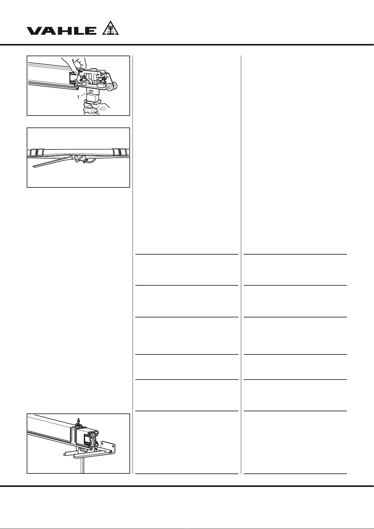
Schrauben Sie die Bolzen der Fest-
aufhängungen in die Aufhängeklam-
mern ein und befestigen Sie sie an
den Konsolen (G1).
Die zwei beiliegenden Unterlegscheiben
an den Aufhängebolzen der Fest- und
Gleitaufhängungen nur bei Befestigung
in Langlöchern verwenden.
a) KBSL
Befestigen Sie die einteiligen Gleit-
aufhängungen an den Konsolen.
Schieben Sie die Schleifleitung in die
Gleitaufhängung ein (G2).
b) KSL, KSLT
Montieren Sie die Gleitaufhängungen
am nächsten Teilstück vor.
Mounting support brackets
Bolt EHK standard brackets or weld
steel angles with slotted holes.
HObserve the following installa-
tion distances:
Max. support distance 2000 mm
for indoor and roofed outdoor
installations with a ambient tem-
perature upto 35 °C).
Max. 1333 mm for outdoor in-
stallations, special indoor
systems with high ambient
temperatures (>35-60 °C) and
systems with heating. The first
and last hanger must be placed
at least 250 mm and no more
than 500 mm from the end of a
powerail section. The distance of
the sliding hangers from the joint
material, end caps, feed points,
etc. must measure at least
250 mm and up to 500 mm to
guarantee free expansion (S2).
Installation of the powerail
Install the powerail straight and paral-
lel to the machinery track.
HFree expansion of the powerail
away from the fixpoints must
be possible. Provisionally an-
chor the first powerail section
with two fixpoint hangers to fa-
cilitate the further mounting
procedure. These two fixpoint
hangers must be replaced by
sliding hangers after system in-
stallation has been completed.
If you install a straight run, install two
fixpoint hangers approximately at the
center of the system or in accordance
with the layout plan (S1) and (S2).
Screw the bolts into the clamps and
fix these to the brackets (G1).
Use the two washers of the fixpoint and
sliding hangers only for fixture in slotted
holes.
a) KBSL
Fix the solid sliding hangers to the
brackets.
Push the powerail into the sliding
hangers (G2).
b) KSL, KSLT
Pre-install the sliding hangers on the
next powerail section.
G1
G2
KBSL

KBSL • KSL • KSLT
6
Montageanleitung •Mounting instructions
Lösen Sie die Muttern der Aufhänge-
schrauben und setzen Sie die Gleit-
aufhängungen über das Schleiflei-
tungsprofil (G3).
HDer Abstand der Gleitaufhän-
gungen von den Verstärkungs-
klammern, Verbindungsmateri-
al, Endkappen, Einspeisungen
usw. muss mindestens 250 mm
betragen, um die Ausdehnung
nicht zu behindern.
SBeschädigungsgefahr für die
Stromschienen!
Bei der Befestigung an den
Konsolen dürfen Sie die Gleit-
aufhängungen nicht verdre-
hen, damit sich die Schleiflei-
tung frei bewegen kann.
Schleifleitung ausrichten
Richten Sie die Schleifleitung seitlich
aus, indem Sie die Aufhängebolzen in
den Langlöchern der Konsolen ver-
schieben. (Bei der EHK durch Ver-
schieben der Halterungen (1).)
Stellen Sie die Höhe mit den Muttern
ein (G4).
HDie Schleifleitung muss genau
parallel zur Kranbahn montiert
werden!
Stromschienen- und Gehäuse-
verbindungen für KBSL, KSL,
KSLT
BÜber 100 A dürfen nur noch
Schraubverbinder verwen-
det werden!
SBeschädigungsgefahr für die
Feder-Steckverbinder!
Die Enden der Feder-Steckver-
binder nur elastisch zusam-
mendrücken, damit die Feder-
kraft nicht verringert wird.
a) Schleifleitung mit Feder-Steck-
verbindern
Drücken Sie die Feder-Steckverbin-
der zusammen und stecken Sie sie in
die Stromschienen ein (G5).
Schieben Sie das nächste gleitend
aufgehängte Teilstück gegen das er-
ste Teilstück.
Drücken Sie die Feder-Steckverbin-
der zusammen und führen Sie sie ein-
zeln ein kurzes Stück in die Kupfer-
schienen ein (G6).
Schieben Sie die Teilstücke zusam-
men (G7).
Loose the nuts of the suspension
screw and place the sliding hanger on
the powerail section (G3).
HThe distance between sliding
hangers and clamps, feed sets
etc. shall be at least 250 mm in
order to enable free expansion.
SRisk of damage to the con-
ductor rails!
Make sure that the sliding
hangers are straight (in a per-
pendicular position) after nuts
have been tightened to guaran-
tee free sliding of the powerail.
Alignment of the powerail
Align the powerail sections laterally
by sliding the support bolts as de-
sired in the slotted holes of the brack-
ets. (On the EHK bracket, by sliding
the supports (1).)
Adjust the height by means of the
nuts (G4).
HThe powerail sections must be
precisely aligned to the track
and to each other!
Powerail and housing joints for
KBSL, KSL, KSLT plants
BAbove 100 Ampere, you may
only use bolted joints!
SRisk of damage to the
plug-in-joints!
Compress the ends of the
plug-in-joints only elastically to
avoid any reduction of the
elastic force of the spring!
a) Powerail with plug-in-joints
Compress the plug-in-joints and in-
troduce them in the conductors (G5).
Push the next powerail section (sus-
pended from sliding hangers) against
the first section.
Compress the plug-in-joints and in-
troduce them partially into the copper
conductors (G6).
Now push the powerail sections to-
gether (G7).
G5
G6
G7
G4
G3
KSL, KSLT

b) Powerail with bolted joints
Insert the bolted joints in the copper
conductors of the assembled section;
the bolt heads shall point downwards
(G8).
HThe upper connectors must be
installed first. To do so, shift
the lower connectors towards
the right or left.
Push the next powerail section (sus-
pended from sliding hangers) against
the first section and insert the bolted
joints into the copper conductors.
Push the powerail sections together
and tighten the bolted joints cen-
trically (G9).
Tightening torque = 4 Nm
Smoothing the joints
The inspection hole in the housing allows
to control the copper conductors opti-
cally and by touch.
If necessary, smooth the joints with
emery cloth (G10).
Housing joints and end caps
Position the joint cap centrically on
the joint.
The lips of the caps shall engage the
grooves (1) of the powerail profile (G11).
Press the clipable joint caps together
(G12).
To check the joint, insert a current
collector (see section "Inserting cur-
rent collectors") and push it along the
section.
Put the end caps on the powerail
ends.
Bolt the end caps to the powerails
(G13).
Insertion of current collector
BRisk of injury by electric
shock!
Prior to inserting or removing a
current collector, disconnect
the powerail from the mains!
KBSL • KSL • KSLT
7
Montageanleitung •Mounting instructions
b) Schleifleitung mit Schraubverbindern
Setzen Sie die Schraubverbinder in
die Kupferschienen des montierten
Teilstücks ein, die Schraubenköpfe
müssen nach unten weisen (G8).
HDie oberen Verbinder müssen zu-
erst montiert werden. Verschieben
Sie die unteren Verbinder hierzu
nach rechtsoder links.
Schieben Sie das nächste gleitend
aufgehängte Teilstück gegen das er-
ste Teilstück und führen Sie die
Schraubverbinder in die Kupferschie-
nen ein.
Schieben Sie die Teilstücke zusam-
men und ziehen Sie die Schraubver-
binder mittig fest (G9).
Anzugsmoment = 4 Nm
Verbindungsstellen glätten
Die Öffnung im Gehäuse ermöglicht eine
Sicht- und Tastkontrolle der Kupfer-
schienen.
Glätten Sie ggf. die Verbindungsstel-
len mit Schmirgelleinen (G10).
Gehäuseverbindungen und
Endkappen
Setzen Sie die Stoßabdeckkappen
mittig auf die Verbindungsstelle.
Die Stege der Kappen müssen in die Nu-
ten (1) des Schleifleitungsprofils einra-
sten (G11).
Drücken Sie die klipsbaren Stoßab-
deckkappen zusammen (G12).
Setzen Sie zur Überprüfung der Ver-
bindungsstelle einen Stromabnehmer
ein (siehe Kapitel „Stromabnehmer
einsetzen“) und fahren Sie damit
durch den Bereich.
Stecken Sie die Endkappen auf die
Schleifleitungsenden auf.
Verschrauben Sie die Endkappen mit
den Schleifleitungen (G13).
Stromabnehmer einsetzen
BVerletzungsgefahr durch
Stromschlag!
Bevor Sie die Stromabnehmer
ein- oder ausbauen, müssen
Sie die Schleifleitung span-
nungslos schalten!
G11
G12
G13
G10
G8
G9

KBSL • KSL • KSLT
8
Montageanleitung •Mounting instructions
Führen Sie den Stromabnehmer am
Ende der Schleifleitung ein.
Durch den Sicherheitsanschlag (1) am
Stromabnehmer wird falsches Einsetzen
verhindert (G14). Der Ein- oder Ausbau der
Stromabnehmer erfolgt normalerweise an
den Enden der Schleifleitung. Der Stromab-
nehmer kann auch auf der Strecke ein- oder
ausgebaut werden siehe Ausbauteilstück
Seite 12 oder (G15).
Lösen Sie die zwei Verstärkungs-
klammern (falls vorhanden) und
schieben Sie sie an die Nachbarklam-
mern.
Nehmen Sie den Stromabnehmer aus
der Schleifleitung heraus.
Kontrollen
Überprüfen Sie die Schlitzbreite auf
der ganzen Länge.
KBSL/KSL/KSLT = 11 mm
Wenn der Schlitz zu eng ist, können Sie ihn im
Bereich der Verstärkungsklammern mit ei-
nem Hilfswerkzeug auf Maß bringen (G15).
Bei einer Schlitzbreite über dem Sollmaß
müssen Sie die Verstärkungs- und Stoßhalte-
klammern demontieren und richten.
HDer Schlitz kann mit einem
Hilfswerkzeug (80 mm breit)
mit abgerundeten Ecken auf-
gebogen werden.
Mechanische und elektrische
Verbindung
B
Verletzungsgefahr durch
Stromschlag!
Bevor Sie die elektrische Verbin-
dung herstellen, müssen Sie die
Anlage spannungslos schalten!
Schließen Sie die Einspeisung an das
Stromnetz an (siehe Kapitel „Kopfein-
speisung montieren“).
SBeschädigungsgefahr durch
Verpolung!
Achten Sie auf die Polzuord-
nung des Stromabnehmers!
Verdrahten Sie den Stromabnehmerwa-
gen mit dem Verbraucher. Verlegen Sie
den freihängenden Teil der Anschlusslei-
tung mit einem Minimal-Biegeradius von
10 x Leitungsdurchmesser.
Stellen Sie die mechanische Verbin-
dung zwischen Stromabnehmer und
Verbraucher durch den Mitnehmer
her (G16).
Insert the current collector at the end
of the powerail.
The safety key (1) on the current collector
prevents erroneous insertion (G14).
Current collectors are usually inserted or
removed at the end of the powerail. The
current collector can be inserted or
removed anywhere along the powerail
with a removing section from page 12 or
(G15).
Loosen the two stiffener clamps (if
present) and shift them to the neigh-
bouring clamps.
Take the current collector out of the
powerail.
Inspections
Check the slot dimension on the
entire length
KBSL/KSL/KSLT = 11 mm
If the slot is too narrow, you can enlarge it
close to the stiffener clamps using a suit-
able tool (G15). If the slot is wider, disas-
semble and straighten the stiffener and
joint clamps accordingly.
HThe slot can be bent open us-
ing an auxiliary tool (width 80
mm) with rounded corners.
Mechanical and electrical con-
nections
BRisk of injury by electric
shock!
Before you make any electric con-
nection, ensure you have discon-
nected the system from the mains!
Now connect the feed point to the
power supply (e.g. mains, see section
"Installation of the end feed").
SRisk of damage by phase
reversing!
Observe the pole allocation of
the current collector!
Wire the current collector trolley to the
electric consumer. Install the suspended
part of the connecting cable so that its
bending radius will always be larger than
10 times the cable diameter.
Make sure the mechanical link be-
tween current collector trolley and
electrical consumer by means of the
towing arm (G16).
G16
G15
G14

KBSL • KSL • KSLT
9
Montageanleitung •Mounting instructions
S
Beschädigungsgefahr für die
Stromabnehmer!
Die Anschlussleitungen dürfen
die Beweglichkeit des Strom-
abnehmers nicht behindern!
HSchalter, Sicherungen und Ka-
bel zur Verdrahtung sind kun-
denseitig bereitzustellen und
zu montieren.
Kopfeinspeisung
Schlagen Sie Verstärkungsprofile (1)
auf die Kupferschienenenden der
Schleifleitung auf.
Treiben Sie den Anschlussbolzen (2)
bis zum Anschlag in die Kupferschie-
nen ein (G17).
Montieren Sie die Leitungsverschrau-
bung M32, den Blindstopfen und die
zwei Bohrschrauben am Kasten vor.
Stecken Sie den Kasten auf das
Schleifleitungsende und fixieren Sie
ihn mit den zwei Schrauben (G18).
Setzen Sie die Anschlussleitung etwa
75 mm auf Einzeladerlänge ab.
Bringen Sie die Kabelschuhe an den
Einzeladern an und führen Sie die An-
schlussleitung durch die Kabel-Ver-
schraubung.
Schrauben Sie die Kabelschuhe mit
den Sechskantschrauben (M5), Fä-
cherscheiben und Sechskantmuttern
an die Anschlussbolzen (G19).
Ziehen Sie die Kabel-Verschraubung
soweit an, bis eine Abdichtung zur
Anschlussleitung erfolgt.
Montieren Sie den Deckel mit Dichtung.
Streckeneinspeisung
Öffnen Sie den Deckel an der mon-
tierten Streckeneinspeisung (G20).
Setzen Sie die Anschlussleitung etwa
155 mm auf Einzeladerlänge ab.
Kürzen Sie die beiden vorderen Ein-
zeladern für L3 und L1 auf 90 mm
Länge.
Bringen Sie die Kabelschuhe an den
Einzeladern an und führen Sie die An-
schlussleitung durch die Kabel-Ver-
schraubung.
Schrauben Sie die Kabelschuhe mit
den Sechskantschrauben (M8), Fä-
cherscheiben und Sechskantmuttern
an die Anschlussfahnen (G21).
Ziehen Sie die Kabel-Verschraubung
soweit an, bis eine Abdichtung zur
Anschlussleitung erfolgt.
Setzen Sie den Deckel auf und verschlie-
ßen Sie den Anschlusskasten (G22).
SRisk of damage to the
current collector!
The connecting cable may not
restrict the movement of the
current collector!
HSwitches, fuses and cable
used for the wiring shall be
provided and mounted by the
customer.
End feed
Drive reinforcing strips (1) onto the
copper conductor ends of the
powerail.
Hammer the connecting pin (2) into
the copper conductors until the limit
(G17).
Pre-assemble the cable gland M32,
the filler plug and the two self-drilling
screws on the box.
Plug the box onto the powerail end
and fix it with two screws (G18).
Strip approximately 75 mm of the outer
insulation of the connecting cable off so
that the individual wires are accessible.
Fix cable lugs on the individual con-
ductors and run the connecting cable
through the gland.
Fix the cable lugs to the connection
pins using hexagonal bolts (M5), ser-
rated lock washers and hexagonal
nuts (G19).
Tighten the cable gland until sealing
against the connecting cable is
achieved.
Install the box cover with sealing.
Line feed
Open the cover of the previously in-
stalled line feed (G20).
Strip approximately 155 mm of the
outer insulation of the connecting ca-
ble off so that the individual wires are
accessible.
Shorten the two front wires L3 and L1
to 90 mm.
Fix cable lugs on the individual con-
ductors and run the connecting cable
through the cable gland.
Fix the cable lugs to the line feed ter-
minals using hexagonal bolts (M8),
serrated lock washers and hexagonal
nuts (G21).
Tighten the cable gland until sealing
against the connection is achieved.
Put the cover on the terminal box and
fix it (G22).
G17
G18
G19
G20
G21
G22

KBSL • KSL • KSLT
10
Montageanleitung •Mounting instructions
HIn die Nähe der Einspeisungen die
Festaufhängungen setzen oder
abweichend nach Verlegungsplan
mit Gleitaufhängungen und flexi-
bler Anschlussleitung.
Überleitungseinführungen
Bei der KBSL und KSL können die Über-
leitungseinführungen wahlweise am lin-
ken oder am rechten Teilstück-Ende
montiert werden.
Für die KSLT gibt es linke und rechte
Ausführungen. Sie werden mit „L“ und
„R“ gekennzeichnet.
Die Zuordnung des linken oder rechten
Teilstück-Endes wird durch den Blick auf
den kurzen Steg festgestellt (G23).
Weiterhin gibt es gerade Ausführungen
(G24) und schräge Ausführungen (G25).
Die Anschrägungen werden werkseitig
vorgenommen.
Lösen Sie die untere Mutter des Auf-
hängebolzens und heben Sie das
Halteblech an.
Stecken Sie die Überleitungseinfüh-
rung auf das Schleifleitungsende auf.
Das Halteblech greift in die oberen
Nuten der Schleifleitung ein.
Ziehen Sie die untere Mutter an.
Montieren Sie die Überleitungsein-
führung an die vorhandenen Konso-
len.
HAn jeder Überleitungseinfüh-
rung muss die Schleifleitung
mit zwei Festaufhängungen
stabilisiert werden (Abstand
0,3 bis 0,8 m).
SBeschädigungsgefahr für die
Stromabnehmer und Über-
leitungseinführungen.
Der Luftabstand zwischen den
Überleitungseinführungen darf
20 mm nicht überschreiten!
(S3) Der seitliche Versatz der ge-
genüberstehenden Überlei-
tungseinführung beträgt ±8 mm,
der Höhenversatz ±3 mm.
HPlace fixpoint hangers close to
the feed point or corre-
sponding to the layout with
sliding hangers and flexible
connecting cables.
Transfer guide
For KBSL and KSL, the transfer guides
can be placed either on the left or on the
right end of a powerail section.
For KSLT, there are left-hand and right-
hand versions available. They are identi-
fied by an "L" or an "R".
The decision whether to employ a left-
hand or a right-hand version is taken ob-
serving the short lip of the powerail sec-
tion end (G23).
Furthermore, there are straight (G24) and
oblique versions (G25). The oblique cut is
prepared by the manufacturer.
Loosen the lower nut of the fixpoint
bolt and lift the suspension clamp.
Plug the transfer guide onto the
powerail end. The suspension clamp
fits into the upper groove of the
powerail.
Tighten the lower nut.
Mount the transfer guide to the ex-
isting brackets.
HOn each transfer guide, the
powerail shall be stabilised by
two fixpoint hangers
(distance 0.3 to 0.8 m).
SRisk of damage for collector
and transfer guide!
The air gap between the trans-
fer guide may not exceed
20 mm! (S3) The admissible
lateral offset among op-posing
transfer guides is ±8 mm, the
admissible height offset is
±3 mm.
G23
G24
140
G25

KBSL • KSL • KSLT
11
Montageanleitung •Mounting instructions
Legende/Legend S3
1Streckeneinspeisung
line feed
2Kranbahn
runway
3Stoß
joint
4Überleitungseinführungen (gerade)
transfer guide (straight)
5Überleitungseinführungen (schräg)
transfer guide (oblique)
6Festaufhängung
fixpoint hanger
7Abstand 5 bis 20 mm
distance 5 to 20 mm
1
5
7
0,3-0,8m
6
2
4
3
S3
Schiebeweiche
sliding switch
Einführungstrichter
Es gibt linke und rechte Ausführungen.
Sie werden mit „L“ und „R“ gekennzeich-
net.
Die Zuordnung des linken oder rechten
Teilstück-Endes wird durch den Blick auf
den kurzen Steg festgestellt (G26).
Demontieren Sie die Stoßabdeckkappen.
Führen Sie die Steckverbinder des
Trichters in die Kupferschienen des
vormontierten Schleifleitungsteil-
stücks ein.
Decken Sie den Trichter mit einem
Holzstück o. ä. ab und treiben Sie ihn
durch Hammerschläge vor.
Montieren Sie die Stoßabdeckkappe
(siehe Kapitel „Gehäuseverbindungen
und Endkappen“).
Setzen Sie die Konsole für die Auf-
hängung am Trichter.
HAn jedem Einführungstrichter
muss die Schleifleitung mit zwei
Festaufhängungen stabilisiert
werden (Abstand 0,3 bis 0,8 m).
Montieren Sie die Schleifleitung mit dem
Trichter so, dass sie auf 2 bis 3 m Länge
um 5 bis 10 mm abfällt, damit der Strom-
abnehmer an der oberen Schräge des
Trichters einfährt. Auf der Strecke der
dahinter liegenden Schleifleitung soll der
Stromabnehmer so fahren, dass er durch
die Blattfeder der Federmitnahme leicht
auf die Lauffläche der Schleifleitung
gedrückt wird (S4).
SBeschädigungsgefahr für die
Stromabnehmer und Einfüh-
rungstrichter!
Der max. seitliche Versatz der
Achsen Stromabnehmer - Einfüh-
rungstrichter beträgt 15 mm,
Höhenversatz 10 mm.
Transfer funnel
There are left-hand and right-hand ver-
sions available. They are identified by an
"L" or an "R".
The decision whether to employ a left-
hand or a right-hand version is taken ob-
serving the short lip of the powerail sec-
tion end (G26).
Dismantle the joint caps.
Insert the plug-in-joints of the funnel
into the copper rails of the pre-as-
sembled powerail section.
Protect the funnel end by a piece of
wood or similar and drive it in with a
hammer.
Install the joint cap (see section
"Housing joints and end caps").
Place the suspension bracket on the
funnel.
HAt each transfer funnel, the
powerail shall be stabilised by
two fixpoint hangers
(distance 0.3 to 0.8 m).
Install the powerail with the funnel with
an inclination of 5 to 10 mm on a length
of 2 to 3 meters so that the current
collector will easily move along the upper
bevel of the funnel. On the powerail
section behind the funnel, the current
collector should run in a way that it will
be slightly pressed against the runway of
the powerail by the plate spring of the
flexible towing arm (S4).
SRisk of damage for collector
and transfer funnel!
Max. lateral disalignment of
axles of collector - transfer
funnel 15 mm, vertical
disalignment 10 mm.
G26
G27

KBSL • KSL • KSLT
12
Montageanleitung •Mounting instructions
5- 10 mm
290
2
3
X
= 95 SKN
X = 105 SKNT
0,3 - 0,8 mmax. 2 m
1
x
Legende/Legend S4
1Festaufhängungen
fixpoint hangers
2Gefälle auf ca. 2 - 3 m
descent on a 2 - 3 m section
3Stromabnehmer mit
Federmitnahme
current collector with flexible
towing arm
S4
Ausbauteilstück
An den Ausbauteilstücken können die
Stromabnehmer ein oder ausgebaut wer-
den (G28).
Es gibt sie für Einzel- und Doppelstrom-
abnehmer.
B
Verletzungsgefahr durch
Stromschlag!
Bevor Sie das Ausbauteilstück
öffnen, müssen Sie die Anlage
spannungslos schalten!
Fahren Sie den Stromabnehmer in
den Ausbaubereich.
Lösen Sie die unteren vier Schrauben
(1) (G29).
Ziehen Sie die Laufflächen-Schieber
(2) nach aussen (G29 und G30).
Nehmen Sie den Stromabnehmer
nach unten aus das Kunststoffgehäu-
se (3) (G30).
Zum Einbau des Stromabnehmers
müssen die Laufflächen-Schieber (2)
in der geöffneten Stellung stehen
(G30).
Setzen Sie das Kunststoffgehäuse
von unten in den Stromabnehmer (3)
(G30).
SBeschädigungsgefahr durch
die Stromabnehmer und
Schleifleitung!
Achten Sie beim Einsetzen des Stromab-
nehmers auf den Sicherheitsanschlag
(G14) und die Lage des langen Stegs (P1).
Der Sicherheitsanschlag des Stromab-
nehmers muss zur kurzen Stegseite (4)
weisen (G30).
Verschieben Sie den eingesetzten
Stromabnehmer nach rechts oder
links in dem Schleifleitungsgehäuse.
Schließen Sie die Laufflächenschie-
ber und verschrauben Sie diese
(G30).
G28
80
11
22
G29
G30
112
3
2
2
4
Removing section
With the removing section collectors can
be inserted or removed (G28).
They are available for single or double
collectors.
B
Risk of injury by electric
shock!
Before you open the removing
section, disconnect the powe-
rail from the mains!
Pull the collector in the area of the
removing section.
Loose the 4 lower screws (1) (G29).
Pull the running surface pusher (2)
outwards (G29 and G30).
Take the collector downwards out of
the PVC housing (3) (G30).
To install the collector the running
surface pusher (2) have to be in open
position (G30).
Place the PVC housing from
downwards to the collector (3) (G30).
SRisk of damage by the
collector and the conductor!
Observe while inserting the collector the
safety key (G14) and the position of the
long lip side (P1).
The safety key of the collector has to
point to the short lip side (4) (G30).
Pull the inserted collector to the left
or the right in the housing.
Close the running surface pusher and
screw the housing (G30).

KBSL • KSL • KSLT
Montageanleitung •Mounting instructions
Dehnungsteilstück
Das Dehnungsteilstück nimmt die Län-
genänderung der Schleifleitung bei Tem-
peraturschwankungen auf (G31). Die
Schleifleitung wird dadurch elektrisch
nicht getrennt. Bei der KSLT wird die
Dichtlippe oder die Schlitzabdeckung im
Bereich des Dehnungsteilstücks unter-
brochen.
HÜbergänge siehe auch Kapitel
„Dichtlippe „D“ montieren (bei
KSLT)“ und Kapitel „Schlitzab-
deckungen „FP“ montieren
(bei KSLT)“.
Die maximale Länge zwischen Bögen,
Überleitungseinführungen oder sonsti-
gen Festpunkten beträgt bei einer Tem-
peraturdifferenz von:
t 20 °C = 100 m
t 30 °C = 68 m
t 40 °C = 50 m
t 60 °C = 34 m
t 80 °C = 25 m
Das Dehnungsteilstück wird etwa mittig
zwischen den Festpunkten der Schleiflei-
tung eingebaut (S5 und S6). Die übrige
Schleifleitung wird in Gleitaufhängungen
verlegt. Das Abstandsmaß „a“ richtet
sich nach der Umgebungstemperatur bei
der Montage. Es ist dem Diagramm zu
entnehmen (S7).
Beispiel:
Montagetemperatur = 18 °C
Abstandsmaß „a“ = 50 mm.
SBeschädigungsgefahr der
Schleifleitung und Stromab-
nehmer durch falsches Ab-
standsmaß!
Bei zu geringem Abstand „a“
wird die Schleifleitung bei hö-
heren Temperaturen gestaucht
und verwirft sich -> Stromab-
nehmer klemmt. Bei zu gros-
sem Abstand „a“ kann das
Dehnungsteilstück bei niedri-
geren Temperaturen aus den
Führungen gleiten -> Stromab-
nehmer wird bei der Durchfahrt
zerstört.
13
Expansion section
The expansion section compensates the
change in length of the powerail during
temperature fluctuation (G31). It does not
electrically separate the powerrail sec-
tions. On KSLT plants, the sealing strip or
slot shielding is interrupted in the area of
the expansion section
HFor the junctions, also see the
sections "Installation of sealing
strip "D" (KSLT)" and "Installa-
tion of shielding "FP" (KSLT)".
The maximum length between curves,
transfer funnels or other fixpoints is, ac-
cording to the temperature differences:
t 20 °C = 100 m
t 30 °C = 68 m
t 40 °C = 50 m
t 60 °C = 34 m
t 80 °C = 25 m
The expansion section shall be installed
approximately at the centre between the
powerail fixpoints (S5 and S6). The rest
of the powerail is suspended with sliding
hangers. The length of distance "a" de-
pends on the ambient temperature dur-
ing installation. This length is stated in
the diagram (S7).
Example:
Installation temperature = 18 °C
distance "a" = 50 mm
SRisk of damage of powerail
and collectors by wrong dis-
tance measure!
If the distance „a“ is too small
the powerail will be deformed
during higher temperature ->
collector jams. If the distance
„a“ is too high the telescope
section can slide out of the
guidance during lower temper-
ature -> collector damages
when passing over the section.
G31
Legende S6/S7
1Endkappe
2Kranbahn
3Festaufhängung
4Dehnungsteilstück
5Streckeneinspeisung
6Schleifleitung
Legend S6/S7
1end cap
2machinery track
3fixpoint hanger
4expansion section
5intermediate feed set
6powerail
S5
S6
S7

KBSL • KSL • KSLT
14
Montageanleitung •Mounting instructions
Belüftungsteilstück
Das Belüftungsteilstück wird an den
Übergängen der Schleifleitung von der
Halle ins Freie eingebaut (G32). Es wird
Kondensatbildung und somit ein Verei-
sen der außen liegenden Schleifleitung
vermieden.
Das Belüftungsteilstück muss etwa 0,5
bis 1 m außerhalb der Hallenwand (7)
montiert werden (S8). Die Schleifleitung
wird elektrisch nicht getrennt.
Dichtlippe „D“ (bei KSLT)
Unter 20 m Lieferlänge wird die Dichtlip-
pe von Hand eingedrückt. Ab 20 m liegt
jeder Lieferung ein Montagewagen bei.
Drücken Sie an einem Ende der
Schleifleitung ca. 2 cm Dichtlippe von
Hand ein.
Führen sie den Montagewagen in die
Schleifleitung ein (G33).
Legen Sie die Dichtlippe zum Schlitz
um und drücken Sie sie mit dem
Montagewagen in ihren Sitz ein
(G34).
Die maximale Lieferlänge der Dichtlippe
beträgt 50 m. Bei größeren Längen müs-
sen Sie die Teillängen mit einer Lasche
(1) verbinden (S9). Diese Lasche liegt der
Sendung bei.
An den Enden der Schleifleitung müssen
Sie die Dichtlippe mindestens 60 mm
zum Aufsetzen der Endkappen kürzen
und durch den Festsetzer (2) fixieren.
Im Bereich von Überleitungseinführun-
gen, Einführungstrichtern, Teleskopstük-
ken und Dehnverbindern wird die Dicht-
lippe unterbrochen.
Schrägen Sie die Enden der Dichtlippe
an und befestigen Sie sie mit dem
Festsetzer (2).
HSchieben Sie den Festsetzer
dazu in die Nut des Schleiflei-
tungsprofils ein und fixieren Sie
ihn mit der Feststellschraube (3).
Anti-condensation section
The anti-condensation section is in-
stalled at the passing between the
powerail sections inside and outside the
hall (G32). It prevents the formation of
condensation and thus, icing on the out-
door sections of the powerail.
The anti-condensation section shall be
installed at a distance of 0.5 to 1 m out-
side of the hall (7), (S8). The powerail is
not separated electrically.
Neoprene sealing strip "D"
(for KSLT)
Below a supply length of 20 m, the
sealing strip is pressed in manually.
Above 20 m a mounting trolley must be
used.
Press approximately 2 cm sealing
strip into the powerail at one end of
the run.
Insert the mounting trolley in the
powerail (G33).
Bend the sealing strip towards the
powerail slot and fix it using the
mounting trolley (G34).
The maximum delivered length of a
sealing strip is 50 m. If you need longer
strips, you need to connect the strip sec-
tions using a clip (1), (S9). This clip is
included in the delivery scope.
At the ends of the powerail, you need to
shorten the sealing strip by 60 mm at least,
and to fix it by means of a fastener (2).
In the area of cross transfer guides,
transfer funnels, telescope sections and
expansion sections, the sealing strip is
interrupted.
Cut the ends of t he sealing strip obliquely
and fix them with a fastener (2).
HTo do so, push the fastener
into the groove of the powerail
profile and fix it using the fixing
screw (3).
Legende S8
1Endkappe
2Belüftungsteilstück
3Streckeneinspeisung
4Festaufhängung
5Schleifleitung
6Kranbahn
7Hallenkontur
Legend S8
1end cap
2anti-condensation section
3line feed
4fixpoint hanger
5powerail
6runway
7contour line of the hall
G32
1 3 4 7 5
6
2
max. 75m
** **
0.5 - 1m 0.5 - 1m
max.75m
S8
G33
G34
3
21
S9
1

KBSL • KSL • KSLT
15
Montageanleitung •Mounting instructions
Schlitzabdeckungen „FP“
(bei KSLT)
Die Schlitzabdeckungen in Längen von
4 m liegen der Sendung bei.
Führen Sie an einem Ende der
Schleifleitung die Schlitzabdeckung
in die vorgesehene Öffnung des
Gehäuses ein.
Rasten Sie die Abdeckung durch
Handdruck ein (G35).
Die Verbindungsstellen der Schlitzabdek-
kungen sollten zur Stabilisierung der
Schleifleitung mindestens 60 mm über-
lappt werden (G36).
Stecken Sie den Kerbstift (1) ca. 10
mm in das montierte Profil ein.
Montieren Sie die Abdeckung des
nächsten Teilstücks wie zuvor.
Führen Sie den Kerbstift ein, decken
Sie das Abdeckprofil mit einem
Schlagschutz ab und treiben Sie es
durch Hammerschläge vor.
Jedes Teil der Schlitzabdeckung müssen
Sie mit einer selbstschneidenden
Schraube (1) festsetzen. Dazu muss bei
der Montage ein Loch von 3 mm Durch-
messer im Abstand von 6 mm zur unte-
ren Kante gebohrt werden (S10).
An den Enden der Schleifleitung müssen
Sie die Schlitzabdeckung mindestens
60 mm zum Aufsetzen der Endkappen
kürzen. Montage der Endkappen (siehe
G13).
Im Bereich von Überleitungseinführun-
gen, Einführungstrichtern, Teleskopstük-
ken und Dehnverbindern wird die Schlitz-
abdeckung unterbrochen.
Schrägen Sie die Enden der Schlitz-
abdeckung an (S9).
Überprüfen Sie die Stoßabdeckkap-
pe und den Sitz der Schlitzabdek-
kung und richten sie eventuell nach
(G36).
Shielding "FP" (for KSLT)
The shielding comes in 4 m standard
sections.
Introduce the shielding in the respec-
tive slot of the housing on one end of
the powerail.
Clip the shielding in, pressing it by
hand (G35).
The junctions of the shielding should
overlap at least 60 mm to stabilise the
powerail (G36).
Insert the connecting peg (1) approxi-
mately 10 mm into the assembled
profile.
Install the shielding of the next
powerail section as described above.
Insert the connecting peg, protect the
shielding profile by an elastic material
(e.g. wood) and drive it ahead with a
hammer.
Each section of the shielding shall be
fixed with a self-tapping screw (1). There-
fore drill a hole of 3 mm in a diameter dis-
tance of 6 mm to the lower edge (S10).
At the end of the powerail, you need to
shorten the shielding by at least 60 mm
so that you can mount the end caps.
Installation of the end caps (see G13)
The shielding is interrupted in the area of
transfer guides, transfer funnels, tele-
scope sections and expansion sections.
Cut the ends of the shielding
obliquely (S9).
Check the joint cap and position of
the shielding; if necessary, adjust
them. (G36).
G35
G36
S10
G37

16
KTW-System mit
KBSL, KSL und KSLT
HKunststoff-Schleifleitung und
Tragschiene sowie Aufhänge-
winkel werden getrennt ver-
packt angeliefert und müssen
in der Reihenfolge Aufhänge-
winkel, Schleifleitung, Trag-
schiene montiert werden.
Aufhängewinkel montieren
Schrauben oder schweißen Sie die
Aufhängewinkel (1) an die vorhande-
ne Stahlkonstruktion (S12).
Der Aufhängeabstand sollte max. 2 m
betragen. Bei höheren Streckenlasten
(> 50 kg) 1 m Abstand.
Richten Sie die Schleifleitung (2) und
die Tragschiene (3) in der Höhe so
aus, dass der Mitnehmer (4) des
Stromabnehmers (5) waagerecht liegt
(S12).
KTW-System with
KBSL, KSL and KSLT
HPowerail, c-track and support
brackets are packed sepa-
rately and shall be installed in
the following order: support
brackets, powerail, c-track.
Installation of support brackets
Bolt or weld the support brackets (1)
to the steel structure (S12).
The distance between the supports shall
not exceed 2 m. With higher loads
(> 50 kg) 1 m distance.
Align powerail (2) and c-track (3)
vertically so that the towing arm (4) of
the current collector trolley (5) as-
sumes a horizontal position (S12).
1 6 2 34 5
7 10 9
4
9
6
108
2000 2000 2000
4000 4000
2000 2000
1500
500
4000
Legende S11
1Schleifleitung
2Verstärkungsklammer
3Verbindungsmaterial
4Festaufhängung
5Mitte der Anlage
6Gleitaufhängung
7Tragschiene S2
8Tragschienenverbinder
9Festpunktaufhängung
10 Gleitaufhängung
Legende/Legend S11
1powerail
2stiffener clamb
3joint pieces
4fixpoint hanger
5center of run
6sliding hanger
7c-track
8c-track joints
9fixpoint hanger
10 sliding hanger
KTW-System mit
KBSL/
KSL/KSLT
KSLT mit
D + FP
Maß a 10 120 1
KTW-System with
KBSL/
KSL/KSLT
KSLT with
D + FP
Measure a 10 120 1
S11
1
3
5
4
2
S12
3 x 180 x 225 lg.
KBSL • KSL • KSLT
Montageanleitung •Mounting instructions

KBSL • KSL • KSLT
17
Montageanleitung •Mounting instructions
Schleifleitung montieren
HSiehe Montageanweisung
KBSL, KSL und KSLT (S1).
Tragschiene montieren
Hängen Sie die Tragschiene parallel
zur Schleifleitung gemäß Skizze (S12)
auf.
HFestpunktaufhängungen ha-
ben seitlich je eine Schraube
zum Festsetzen der Tragschie-
ne.
Hängen Sie die folgenden Teilstücke
in Gleitaufhängungen auf und verbin-
den Sie sie mit Tragschienenverbin-
dern.
Stromabnehmer und Tragwa-
gen einsetzen
BVerletzungsgefahr durch
Stromschlag
!
Bevor Sie die elektrische Ver-
bindung herstellen, müssen
Sie die Anlage spannungslos
schalten!
Setzen Sie Stromabnehmer und Trag-
wagen mit den vorgesehenen Gerä-
ten paarweise an den Enden ein.
HDer Mitnehmer muss den Fuß
des Stromabnehmers gabel-
förmig umfassen.
Pufferanschlag PS 2 und End-
kappe K 40 montieren
Schieben Sie an den Enden der Trag-
schiene die Pufferanschläge auf und
setzen Sie diese fest.
Stecken Sie die Endkappen auf die
Enden der Tragschienen.
Installation of the powerrail
HSee installation procedure
KBSL, KSL, KSLT (sketch S1).
Installation of the c-track
Suspend the c-track parallel to the
powerail according to the scheme
(S12).
HFixpoint hangers have each a
lateral bolt to fix the
c-track.
Suspend the next sections by means
of sliding hangers and connect them
to each other with c-track joints.
Insertion of current collector
and carrier trolley
BRisk of injury by electric
shock!
Before you make any electric
connection, ensure you have
disconnected the plant from
the mains!
Insert current collector and carrier
trolley in pairs together with the
respective machinery at the end of
the rail.
HThe towing arm must hold the
collector like a fork.
Installation of PS 2 bumper and
K 40 end cap
Push the bumper onto the ends of the
c-track and fix them.
Put the end caps on the ends of the
c-tracks.

18
KBSL • KSL • KSLT
Montageanleitung •Mounting instructions
Wartung
BVor beginn der Wartungsarbei-
ten beachten Sie die Sicher-
heitshinweise auf Seite 3.
Schleifleitung
- Geringe Wartung bei normalen Um-
welteinflüssen und Beanspruchungen
- Mindestens jährliche Überprüfung auf
Fremdbeschädigung
- Alle 6 bis 12 Monate - je nach Benut-
zungsgrad bzw. Fahrstreckenleistung
die Schleifleitung mit Pressluft ausbla-
sen oder mit einem Bürsten-Reini-
gungswagen (auf Anfrage lieferbar) vom
losen Staub reinigen
- Schlitzbreite prüfen (11 mm), siehe
Seite 8 ,,Kontrollen“.
Stromabnehmer
- Alle 3 bis max. 12 Monate - je nach
Benutzungsgrad und Fahrstrecken-
leistung - Schleifkohlen und mechani-
sche Teile auf Verschleiß überprüfen
und ggf. austauschen (Ersatzteilliste
Kat. 4a).
- Auf widerstandsfreien Lauf der Strom-
abnehmerwagen achten, d.h. keine Be-
hinderung durch zu enge Führung der
Anschlussleitung.
- Bei Erreichen der Markierung (bei 6 mm)
muss die Schleifkohle gewechselt
werden.
- Austausch der Laufräder (1) und Füh-
rungsräder (2), bei folgenden Durch-
messeränderungen:
Maintenance
BBevor the start of the mainte-
nance work consider the
safety instructions on page 3.
Powerail
- Little maintenance is required in nor-
mal ambient and working conditions.
- Check the rails at least once in a year
for external damage.
- Every 6 to 12 months, - depending on
the frequency of operation and travel
distance -, clean the powerail with
compressed air or with a cleaning col-
lector (on request).
- Check the slot width (11 mm; 14 mm for
KSG plants), see page 8 ,,Inspections“.
Current collector
- Every 3 up to max. 12 months
- depending on the frequency of opera-
tion and travel distance -, check the
carbon brushes and mechanical com-
ponents for wear and replace them if
necessary (for spare parts, refer to cat-
alogue 4a).
- Check the system for easy running of
the current collector trolleys, i.e. there
may be no resistance by an excessively
narrow slot or pull by the connecting
cable.
- When the wear mark of 6 mm is
reached, the carbon brush of the cur-
rent collector needs to be replaced.
- The runner wheels (1) and guide wheels
(2) need to be replaced when their run-
ning diameter reduces as follows: A
G38
Typ SKN/SKNT (G38)
Laufräder Führungs-
räder
Maß
[mm]
von 31,5
auf 29,5
von 29
auf 27
Type SKN/SKNT (G38)
runner
wheels
guide
wheels
Measure
[mm]
from 31,5
to 29,5
from 29
to 27
Typ SKR (G39) komplett Austausch
Laufräder eingenietet
Maß
[mm]
von 25
auf 23
Type SKR (G39) complete exchange
runner wheels riveted
Measure
[mm]
from 25
to 23
G39

KBSL • KSL • KSLT
19
Montageanleitung •Mounting instructions
Notizen:
Notices:

Montageanleitung zu Katalog Nr. 4a/D 2011
Mounting instructions for catalog No. 4a/E 2011
0111 • Printed in Germany • 2504438 • DS • 1000 • 01/2011
PAUL VAHLE GMBH & CO. KG • D 59172 KAMEN/GERMANY • TEL. (+49) 23 07/70 40
DQS - zertifiziert nach DIN EN ISO 9001:2008
OHSAS 18001:2007
(Reg.-Nr. 003140 QM 08/BSOH)
MANAGEMENTSYSTEM
certified by DQS according to Din EN
ISO 9001:2008 OHSAS 18001:2007
(Reg. Nr. 003140 QM 08/BSOH)
This manual suits for next models
2
Table of contents
Popular Cables And Connectors manuals by other brands

Extron electronics
Extron electronics Two Conductor MHR - Mini High Resolution S-Video Cable MHR-2... Specification sheet

Philips
Philips SWV4432S/10 user manual

Simons Voss Technologies
Simons Voss Technologies WaveNet Lock-Node Cable quick guide

Farmnavigator
Farmnavigator 4G Agri installation manual

thomann
thomann Stairville 4 MK II user manual

ADJ
ADJ D6 Branch Assembly instructions