EVAstream Mounting - Installation EVAstream Mounting - Installationwww.evaoptic.com4 5
Electrical shock hazard. Fatal injury will occur. Switch off all electricity near the pool before
installation or service.
Electrical shock hazard. Risk of electric shock and injury. The product must be installed by a certified
electrician. Incorrect installation will cause electrical hazards.
Electrical shock hazard. Risk of electric shock due to incorrect mounting.
lMake sure you read the enclosed documents carefully.
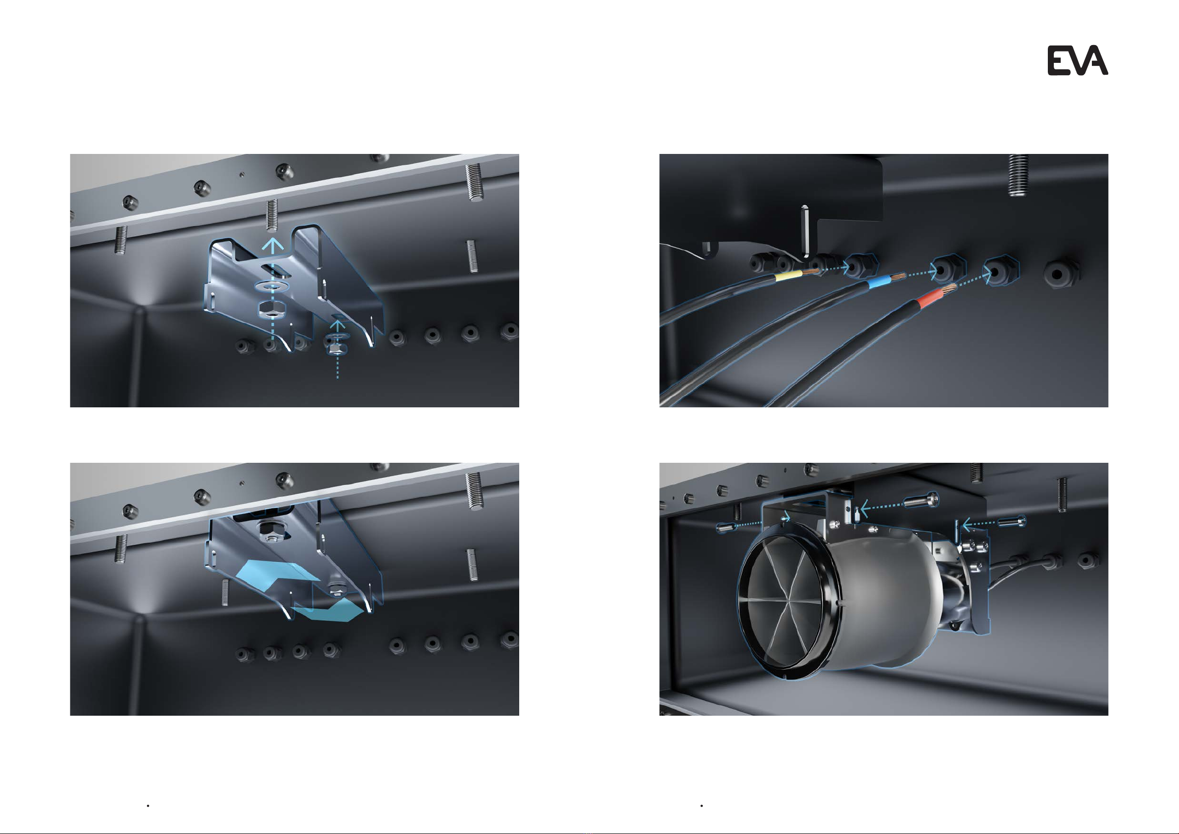
lNever connect the product to the main power before connecting all loose wires properly.
lAlways disconnect the product from the main power before servicing.
Electrical shock hazard. Risk of electric shock due to leakage of current.
lMake sure to install the turbine with a PE-grounding.
Risk of product damage. Prolonged disturbance of frequency may permanently damage
the equipment.
lNever place multiple cables in one conduit.
lNever place the motor control unit near a frequency controller.
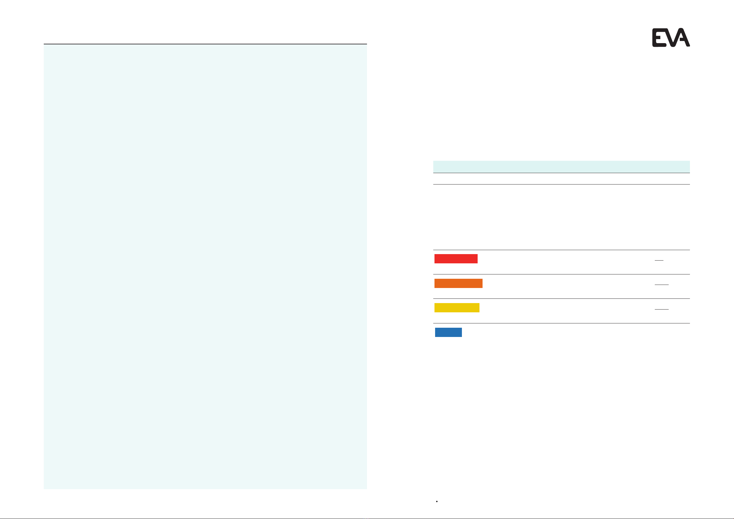
6DANGER
6WARNING
6WARNING
6WARNING
NOTICE
3 Product
3.1 Intended use and reasonably foreseeable unintended use
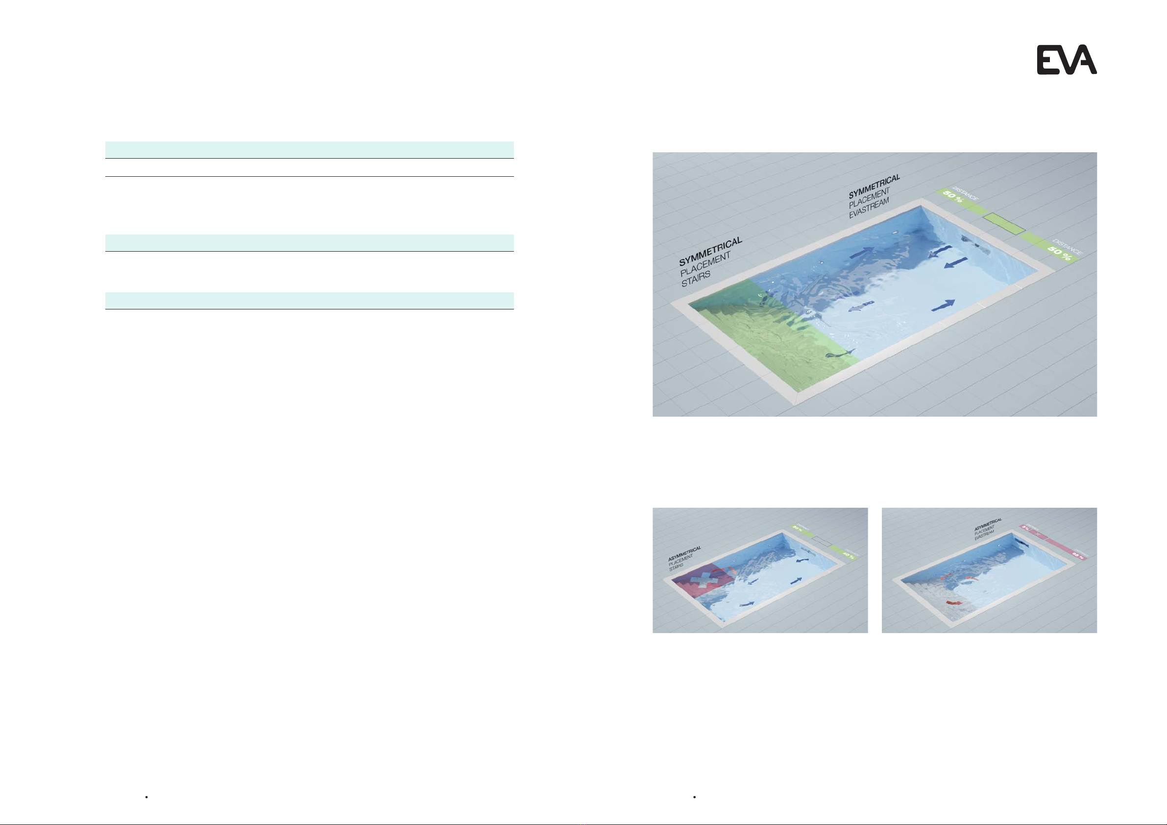
The EVAstream is intended to be used as a counter-current swimming machine. The PIEZO control
panels are intended to be used to control the EVAstream.
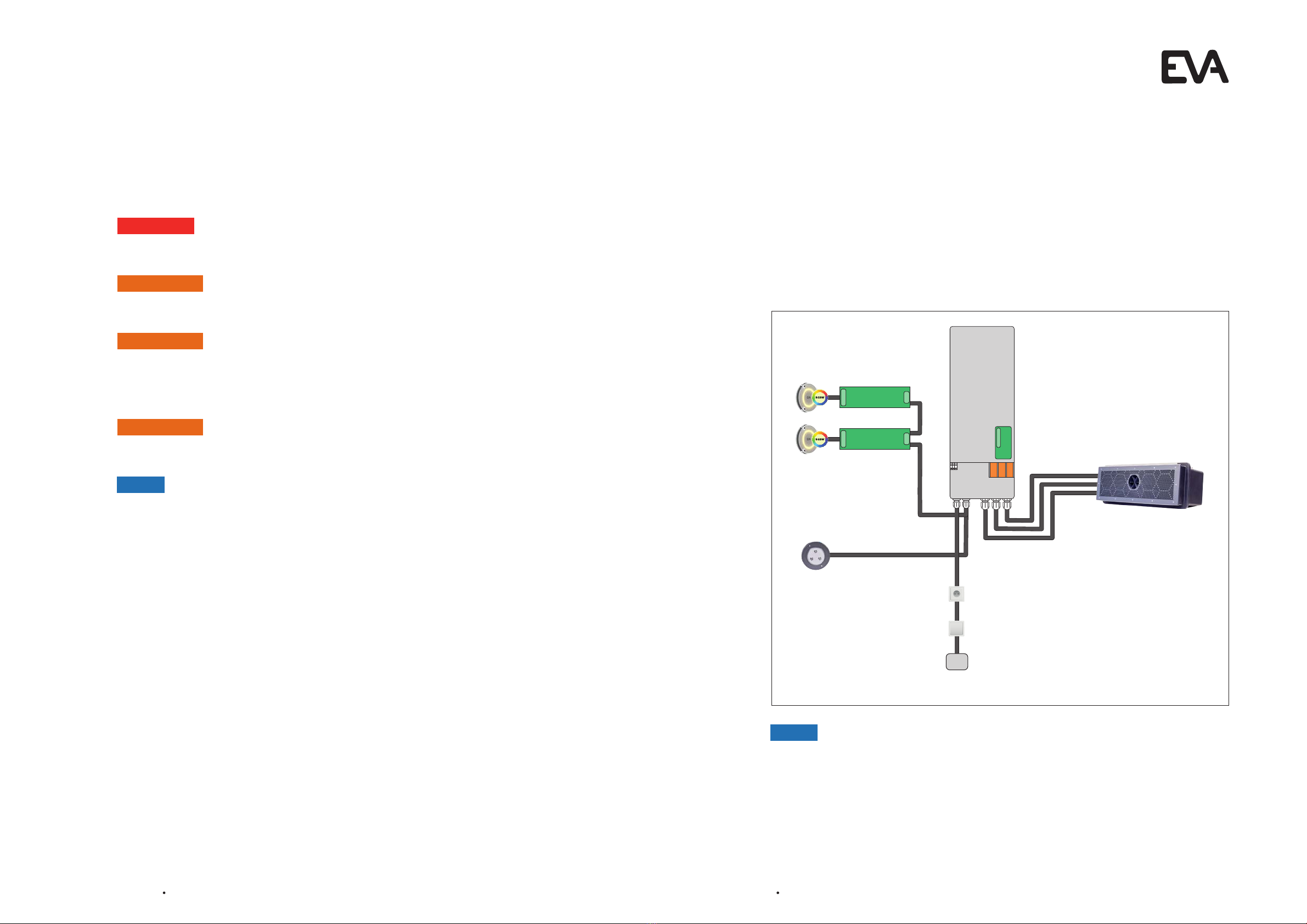
3.2 Description
The EVAstream is a counter-current machine. The machine can be equipped with multiple control
panels and EVA RGBW underwater lighting. The machine is controlled by the motor control unit (MCU).
Risk of product damage. Prolonged disturbance of frequency may permanently damage
the equipment.
lNever place multiple cables in one conduit.
lNever place the motor control unit near a frequency controller.
lFor safety reasons, it is not allowed to mount lights other than EVA Optic to the EVAstream
motor control unit.
2 Safety
2.1 Safety warnings and regulations
230 VAC;
16 A
NOTICE
Overview of an EVAstream configuration
2.2 General safety instructions
Follow the NEN1010 guidelines. Follow the specific installation requirements of IEC 60364-7-702: 2010
(Electric low-voltage installations - Part 7-702: Requirements for special installations, spaces, and
areas – Swimming pools and fountains). Install the controller in or outside of zone 2 (NOT in zones 0
or 1) according to IEC 60364-7-702: 2010. The power supply must be equipped with an earth leakage
circuit breaker (ELCB) with a nominal differential current ≤30mA.
The EVAstream was developed as a counter-current swimming machine for use in a swimming pool.
Use for any other purpose is not permitted. Requests for exceptions to this should be submitted
to the manufacturer for technical analysis. Only after written approval by EVA Tech B.V. may the
EVAstream be applied in any other way than as prescribed in this document.
The general terms and conditions of EVA Tech B.V. apply to all our offers and agreements. EVA Tech
B.V. expressly rejects the applicability of the general (purchasing) conditions of counterparties. The
warranty provisions of the EVAstream and the general terms and conditions of EVA Tech B.V. can be
found at www.evastream.nl