EVAPCO Water Saver EWS-22 Instruction manual
WATER SYSTEMS
Installation, Operation &
Maintenance Manual
For EVAPCO Water Saver TM

2
3 Introduction
3 Water Saver System Overview
3 Standard Equipment and Operation
4 Engineering Data
5 Principle of Operation
5 Water Saver Pretreatment System
6 Design Considerations
8 Makeup Water Tank
9 Clean in Place (CIP)
9 Operational Chemical Feed
10 Field Installation Guidelines
10 Moving the EWS
11 Plumbing the EWS
12 EWS Bypass Loop
12 Wiring Power to the Control Panel
13 Wiring the EWLC and Bypass Solenoid
14 Components
15 Water Flow Path
16 Pressure Regulator Valve
16 Water Meters
16 Conductivity Probe
16 Panel Wiring Locations
17 Operation
17 Startup Program
17 Main Program
17 Shutdown Program
17 Five-Probe Electronic Water Level Control
18 EWS Start/Stop
18 EWS Bypass
18 Hi Level Alarm (By Others)
18 User Display
18 Touch Screen Display
18 Home Screen
19 Operating Data Screen
19 Alarms Screen
19 Alarm Configuration
20 Data Logs
20 Startup and Shutdown
20 Startup Procedure
20 Shutdown Procedures
20 Maintenance
21 Troubleshooting
22 Warranty
Table of Contents

3
Thank you for your purchase of EVAPCO’s Water Saver (EWS), a capacitive deionization pretreatment system. Water Saver
systems are constructed using the highest quality materials and workmanship. Evaporative cooling equipment is often the main
water consumer for a building or process. The Water Saver improves an evaporative unit’s water quality and is designed to
provide years of reliable service when properly maintained.
Qualified personnel should use proper care, procedures, and tools when operating, maintaining, or repairing this equipment in
order to prevent personal injury and/or property damage. The warnings listed below are to be used as guidelines only.
The Water Saver is an electrical device. Use caution when working on or near the Water Saver.
Electrical Hazard – Service and troubleshooting to be completed by trained and authorized service
professionals only.
The Water Saver is an environmentally responsible pretreatment system that offers the following benefits:
x
Improves Evaporative Cooling Water Efficiency by Increasing Operating Cycles of Concentration
x
Reduces Blowdown and Treatment Chemicals Sent to Drain
x
Low Cost of Ownership
x
75-85% Recovery Rate
Standard Equipment and Operation
The Water Saver system is comprised of a control panel, ion removal cylinders, flow sensor, conductivity probes and
interconnecting valves and piping. A nameplate indicating the model number, part number, and serial number is located on the
side of the Control Panel. A 12- cylinder Water Saver (EWS-34) is shown in Figure 1.
The Water Saver is available in nine different cylinder arrangements, engineered to produce a target gal/min of lower
conductivity makeup water to the evaporative unit. Systems come in 4, 6, 8, 9, 12, 15, 18, 20, 24-cylinder designs. Available
voltage configurations are 230V, 3-phase, 3-wire (delta), or 480V, 3-phase, 4-wire (WYE). 480V applications may require a
transformer. Refer to Figure 2 for a basic component schematic.
Figure 1: Evapco Water Saver 12-Cylinder Pretreatment Skid
Introduction
Safety Precautions
Water Saver System Overview
4
Introduction (Continued)
Figure 2: Basic Components
Table 1 shows the Water Saver models that are available and their respective mechanical and electrical specifications for field
installed models.
Model Number Length
(in.)
Width
(in.)
Height
(in.)
Voltage FLA # of
Cylinders
GPM Clean
Makeup
EWS-22
64
46-1/2
83-1/4
230/480
21.5/13.1
4
6 - 10
EWS-23 64 46-1/2 83-1/4 230/480 21.5/13.1 6 9 - 15
EWS-24
64
46-1/2
83-1/4
230/480
21.5/13.1
8
12 - 20
EWS-33 79 46-1/2 83-1/4 230/480 21.5/13.1 9 13 - 22
EWS-34
79
46-1/2
83-1/4
230/480
21.5/13.1
12
18 - 30
EWS-53 115 46-1/2 83-1/4 230/480 36.5/23.1 15 22 - 37
EWS-54 115 46-1/2 83-1/4 230/480 36.5/23.1 20 30 - 50
EWS-63
130
46-1/2
83-1/4
230/480
36.5/23.1
18
27 - 45
EWS-64 130 46-1/2 83-1/4 230/480 36.5/23.1 24 36 - 60
Notes:
1. Unit is designed for indoor installation
2. A sanitary drain is required to dispose flush cycle water
3. Inlet water pressure requirement: Min = 65 psi; Max = 120 psi
4. Electrical Service requirement: 230 V, 3 ph, 3 wire (delta) or 480 V, 3 ph, 4 wire (wye)
5. “GPM Clean Makeup” capacity for each model is variable within the flow rate range shown, dependent of raw makeup water quality
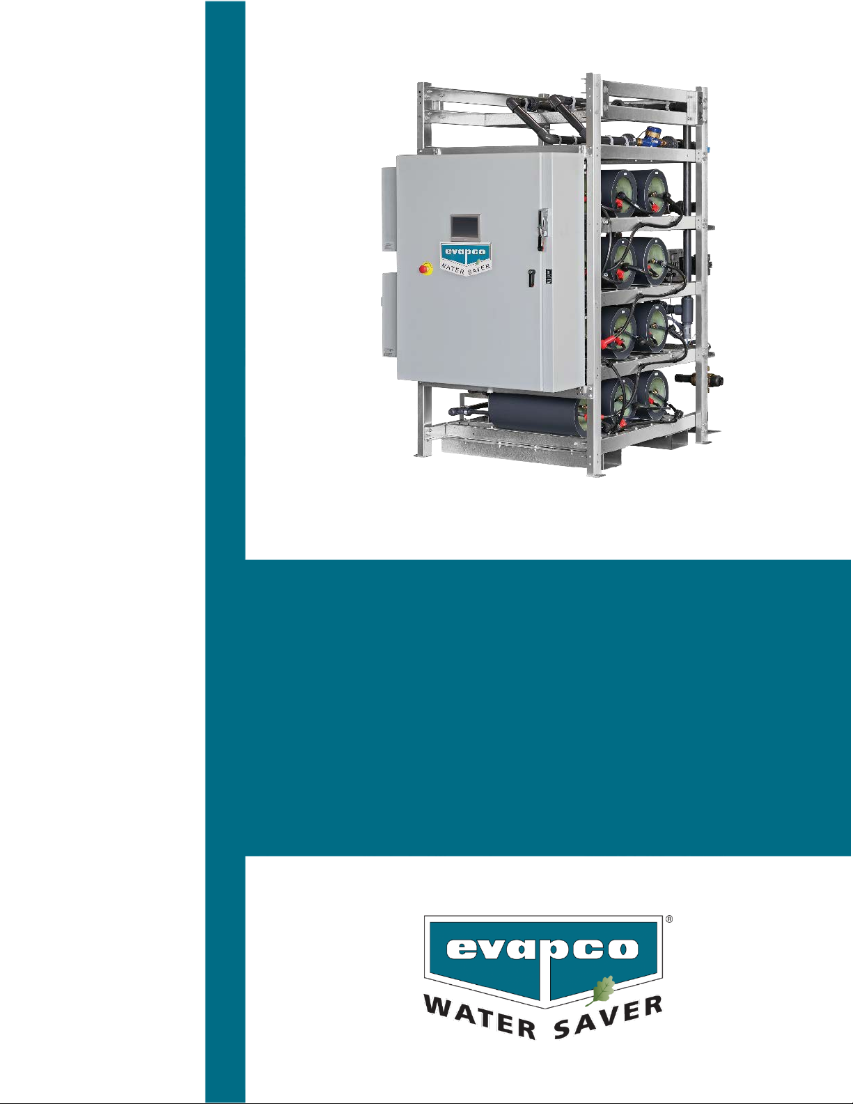
Table 1: Factory Assembled Water Saver Models and Specifications
Control Panel
Cylinder
Model and Serial Number
Nameplate
5
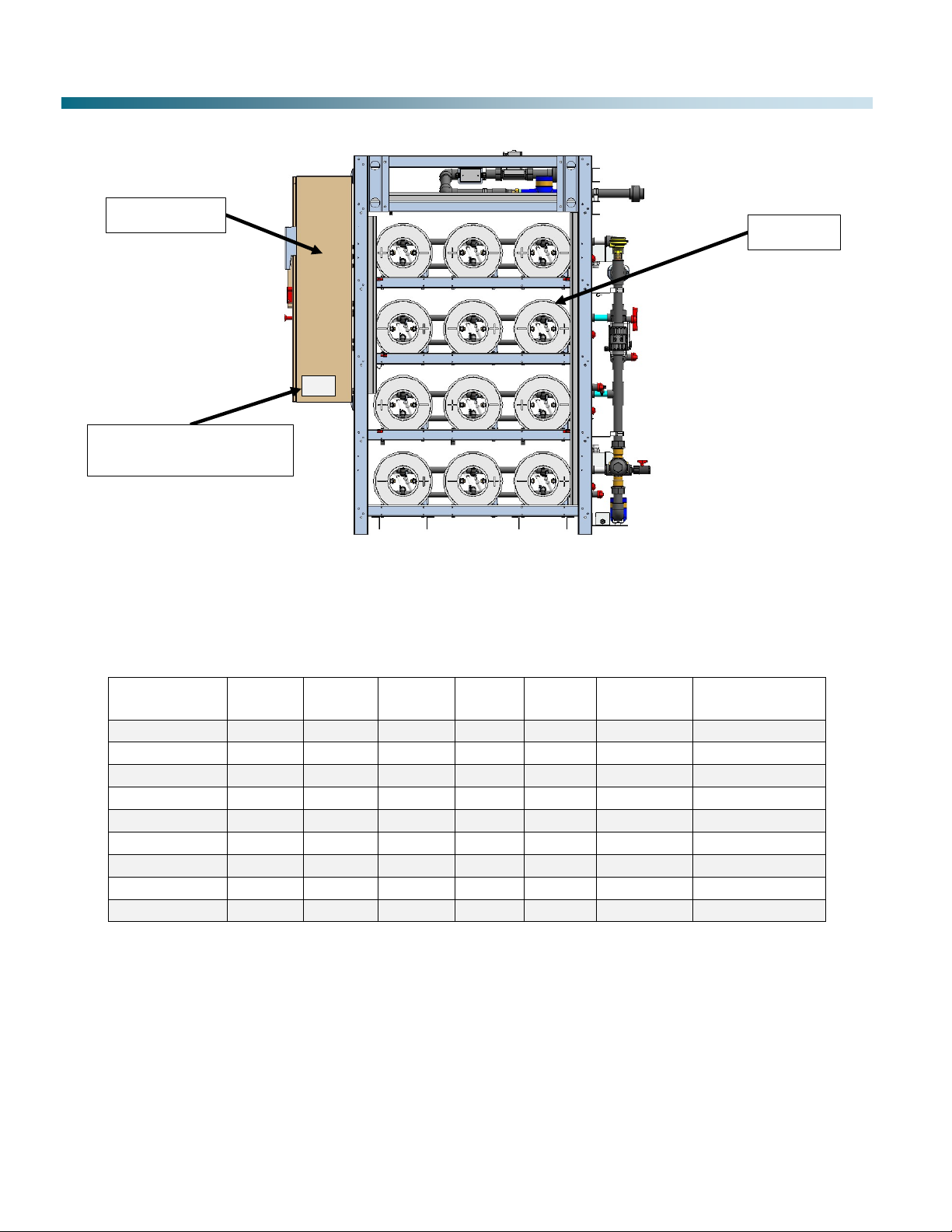
Water Saver Pretreatment System
The Water Saver system uses capacitive deionization technology to reduce dissolved ion concentration, thus lowering the makeup
water conductivity prior to use in an evaporative cooling system. Makeup water entering the Water Saver passes through individual
cylinders which contain oppositely charged supercapacitor surfaces. Dissolved ions (except silica) are removed from the water as
they are adsorbed onto the charged capacitor. A 50% ion reduction allows the operating cycles of concentration to be safely
doubled without an increase in scale or corrosion potential. Figure 3 describes the capacitive deionization process. Figure 4
shows an up-close view of a cylinder.
Figure 3: Illustration of EWS Cycles
Figure 4:Illustration of EWS Cylinder
Principle of Operation
Makeup water flows into a cylinder
Supercapacitors attract oppositely
charged ions from the makeup water
Supercapacitors reverse polarity to
reject ions to drain at reduced flow rate
Raw makeup water
enters the cylinder Reduced conductivity
water exits the cylinder
6
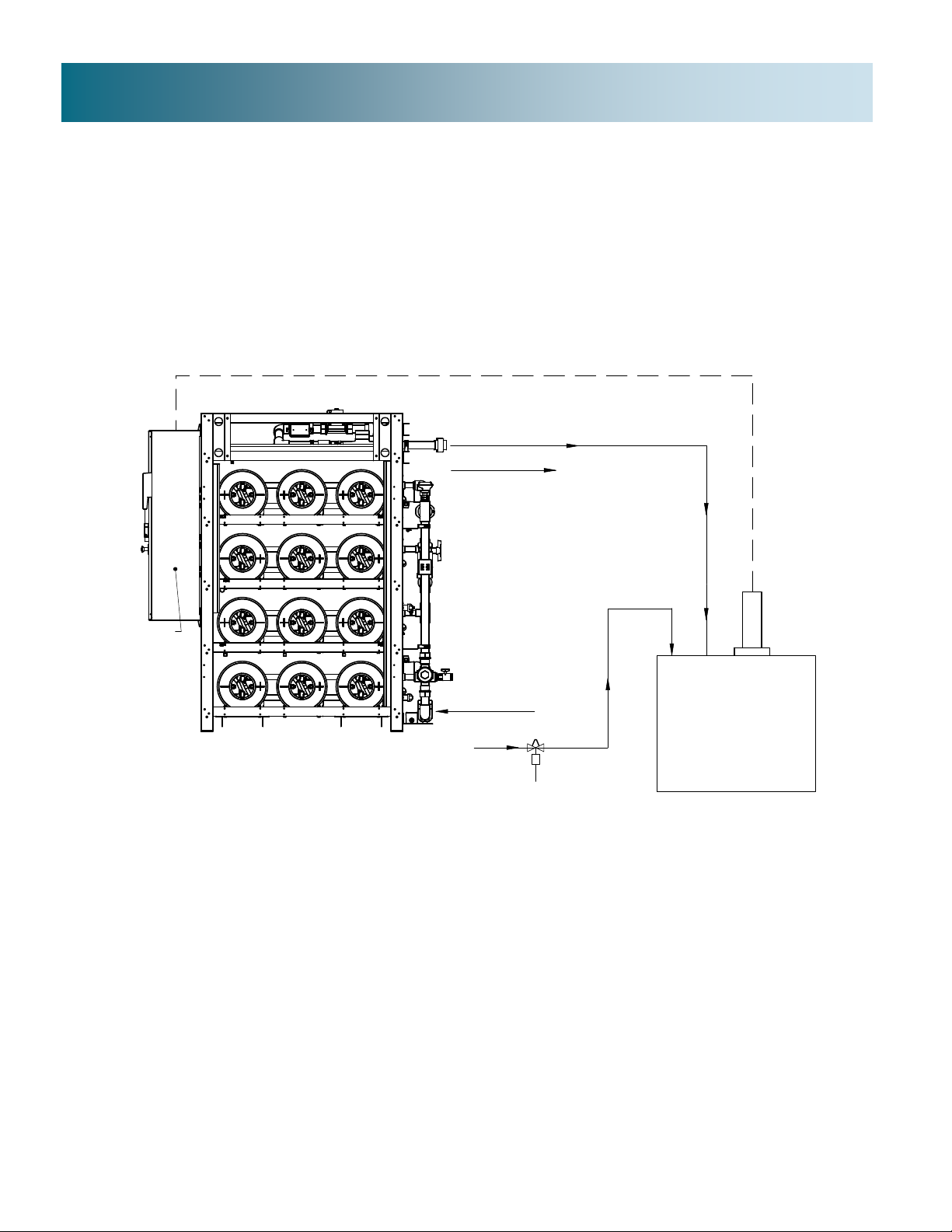
There are multiple standard configurations for field piping and wiring of Water Saver systems based on the evaporative system
design and layout.
xEWS piped directly to a single evaporative unit (see Figure 5)
xEWS piped to a makeup water tank with a single evaporative unit (see Figure 6)
xEWS piped to a makeup water tank with multiple evaporative units (see Figure 7)
Each evaporative unit must be equipped with an Electronic Water Level Controller (EWLC). The EWLC starts Water Saver
operation when makeup water demand is sensed and stops operation when demand is satisfied (see Figure 5). If the system
uses a makeup tank (supplied by EVAPCO), the EWLC (supplied by EVAPCO) on the tank will start and stop Water Saver
operation (see Figure 6 or Figure 7). Makeup water bypass piping and control valve are supplied and field installed (by others)
and are required to ensure the evaporative unit(s) will always have makeup water available.
Figure 5: EWS Field Piping/Wiring for Direct Feed to Single Evaporative Unit
Design Considerations
S
EWS
EVAPORATIVE UNIT
MAKE UP
BYPASS
CLEAN OUTLET, PIPE TO PROCESS
FLUSH OUTLET, PIPE TO DRAIN
(NOT INVIEW)
EWS CONTROL
PANEL
WIRE TO EWLC
POWER AND CONTROL WIRING
E
W
L
C

7
Design Considerations (Continued)
Figure 7:EWS Field Piping/Wiring for Multiple Evaporative Units with Makeup Tank
BOOSTER PUMP REQUIRED
(BY OTHERS)
S
EWS
MAKE UP TANK
MAKE UP
BYPASS
CLEAN OUTLET, PIPE TO PROCESS
FLUSH OUTLET, PIPE TODRAIN
(NOT IN VIEW)
EWS CONTROL
PANEL
P
E
W
L
C
POWER AND CONTROL WIRING
EWLC REQUIRED
EVAPORATIVE UNIT
S
E
W
L
C
POWER AND CONTROL WIRING
WIRE TOEWLC
ON UNIT
EVAPORATIVE UNIT
BOOSTER PUMP REQUIRED
(BY OTHERS)
EWLC REQUIRED
(TYPICAL)
S
EWS
MAKE UP TANK
MAKE UP
BYPASS
CLEAN OUTLET, PIPE TO PROCESS
FLUSH OUTLET, PIPE TO DRAIN
(NOT IN VIEW)
EWS CONTROL
PANEL
WIRE TO EWLC
ON TANK
P
S
E
W
L
C
POWER AND CONTROL WIRING
E
W
L
C
S
E
W
L
C
S
E
W
L
C
WIRE TO UNIT EWLC
POWER AND CONTROL WIRING
POWER AND CONTROL WIRING
POWER AND CONTROL WIRING
EVAPORATIVE UNIT
EVAPORATIVE UNIT
WIRE TO UNIT EWLC
WIRE TO UNIT EWLC
Figure 6: EWS Field Piping/Wiring for Single Evaporative Unit with a Makeup Tank
WIRE TO EWLC
ON TANK
8
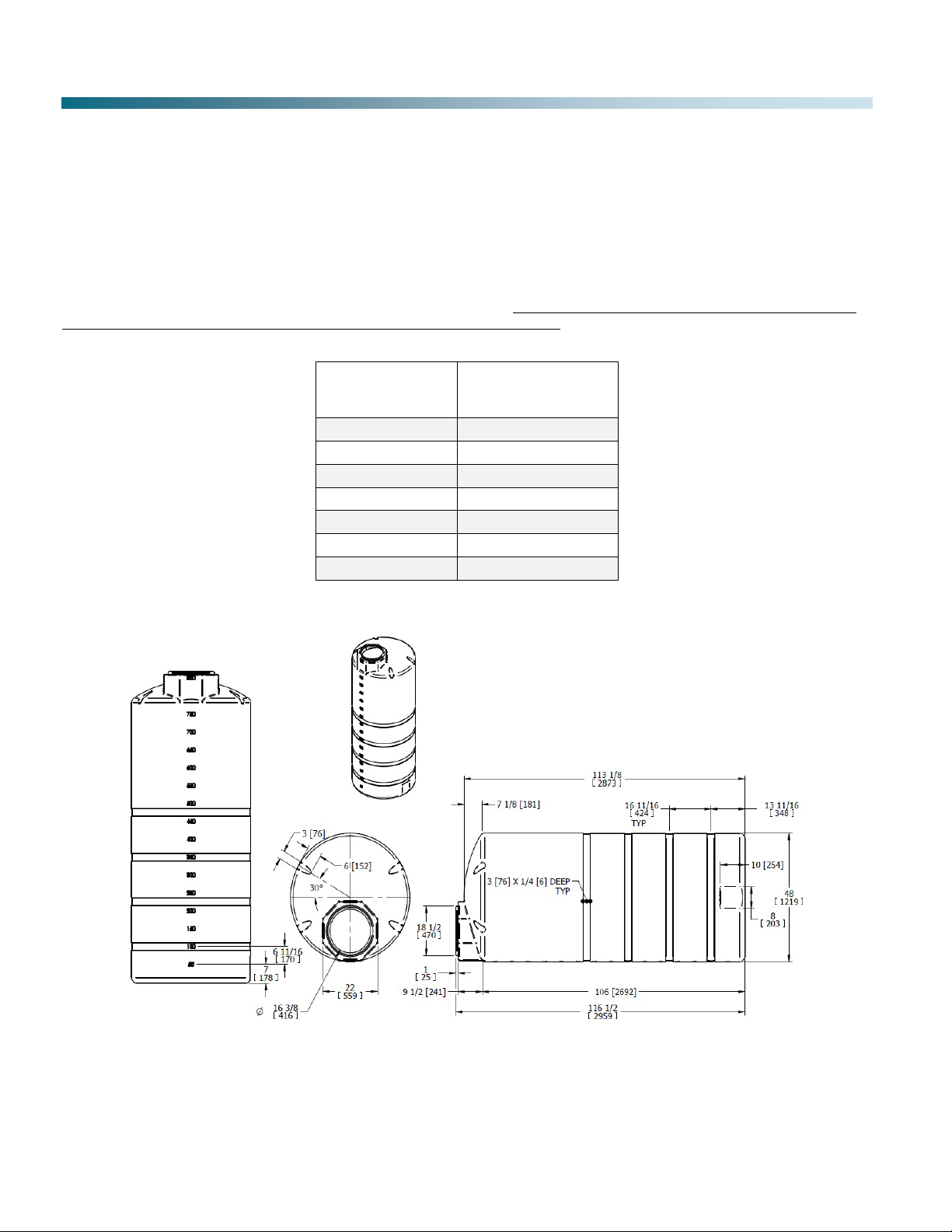
Design Considerations (Continued)
Makeup Water Tank
As determined by system design, the EWS supplies reduced conductivity water to a makeup water tank. A booster pump
(supplied and field installed by others) supplies water from the makeup tank to the evaporative cooling unit(s). Makeup tanks are
sized by evaporative unit demand and supplied by EVAPCO. An 850-gallon tank is shown in Figure 8. All makeup tanks
supplied with the Water Saver(s) have the following connections:
x2” FPT connection at bottom of tank to connect makeup line to evaporative unit
x3” self-aligning connection on top of tank for custom 5 probe EWLC
Clearance above the top of the tank is required for placement of EWLC probes (refer to Table 2 for standard tank sizes). EWS
inlet water should be directed downwards, away from the EWLC probes. Depending upon the height of the mechanical room, the
5-probe EWLC may need to be installed prior to moving the tank into the building. Tank overflow piping is recommended.
Installation and parts for overflow piping is supplied by others.
Make-up Tank
(gallons)
Tank Clearance
(Minimum)
300
79”
500
68”
750
98”
850
112”
1500
110”
2000
120”
2500
82”
Table 2: Minimum Clearance Over Makeup Tank
Figure 8:Makeup Tank 850-gal Capacity

9
Design Considerations (Continued)
Clean-In-Place (CIP)
The Water Saver requires periodic cleaning of the cylinders. CIP equipment supplied with the Water Saver includes a portable
cleaning solution tank, submersible pump, and interconnecting flexible tubing. Water Saver CIP plumbing connections are
integral to the unit. CIP pump discharge is connected to the Water Saver’s CIP inlet. CIP outlet returns to the solution tank. A
sanitary sewer drain will be used during the CIP process. The pump comes equipped with standard 120V maleplug. The Water
Saver has a GFCI utility outlet for this purpose. Refer to Figure 9 for CIP layout.
Figure 9: CIP Equipment
Operational Chemical Feed
The Water Saver may require a chemical feed addition as part of the operating program to maintain performance. A small
chemical feed pump and 5-gallon pail of chemistry is supplied when chemical feed addition is necessary (chemistry is
dependent on makeup water quality and decided by EVAPCO). The pump is powered by the Water Saver.
10
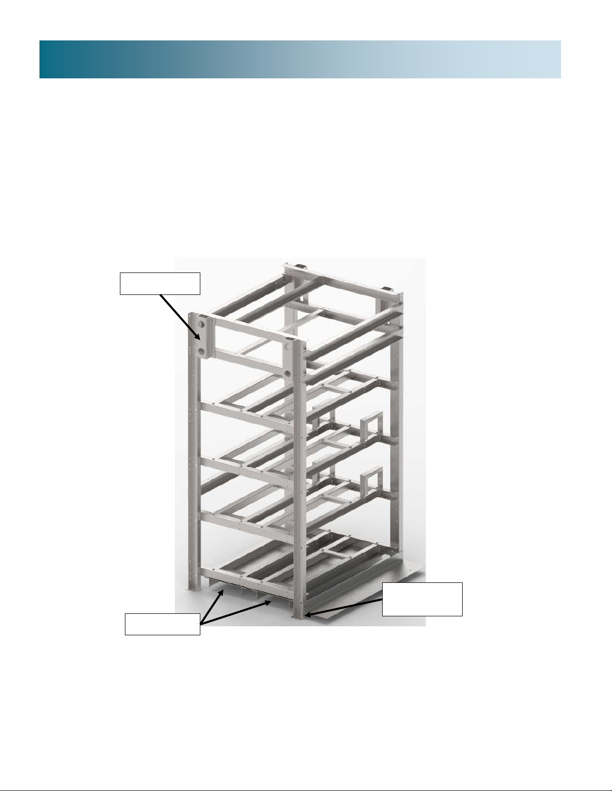
The following needs to be completed in the field prior to starting up the EWS.
Moving the EWS
Forklift Slots
The Water Saver is equipped with forklift slots, hanger brackets, and mounting plates.
If using a forklift,onlyuse the slots marked “FORK HERE” to lift. Equipment damage may result ifEWS islifted from the frame.
Use caution when moving the EWS. The control panel isheavy andcan cause the skid to tip.
Lifting Brackets are located on each corner of the frame.
Mounting Foot Plates
Lagging the Water Saver to the mechanical room floor is recommended. Mounting foot plates with ¾” holes are located on the
EWS frame.
Refer to Figure 10 for lifting and mounting locations.
Figure 10: Lifting and Mounting Locations
Field Installation Guidelines
Lifting Bracket
Mounting Foot
Plate
Forklift Slots
11
Field Installation Guidelines (Continued)
Plumbing the EWS
Inlet (Supply) Piping – see Figure 11
Inlet pipe connections vary by EWS model size. Consult Figure 11 for inlet pipe size. Supply piping (installed and supplied by
others) to EWS inlet must be sized to provide sufficient flow rate and pressure. The minimum inlet pressure is 65 psi. Do not
exceed 120 psi inlet pressure. Schedule 80 PVC supply piping is preferred. Supply piping must not be copper.
Figure 11: Makeup Inlet Plumbing
Clean Outlet
The reduced conductivity (clean) outlet water flow from the EWS is plumbed to either the evaporative unit or the makeup tank.
Due to pressure drop across the EWS (up to 15 psi), some installations may require an inline booster pump (supplied by others)
to get the outlet water flow to the desired destination. A booster pump (supplied by others) is required when a makeup tank is
used to supply makeup to the evaporative unit(s). A totalizing water meter is factory installed prior to shipment.
Flush Outlet
Flush outlet shall be plumbed to a sanitary drain near the EWS. Refer to Figure 12 below for the outlet locations.
Figure 12: Outlet Plumbing (Plan View)
Inlet
Inlet Pipe Diameter
4-12 Cylinders: 1-1/2”
15-24 Cylinders: 2”
Water Meter
Clean Outlet to Unit
or Makeup Tank
Flush Outlet to
Sanitary Drain

12
Field Installation Guidelines (Continued)
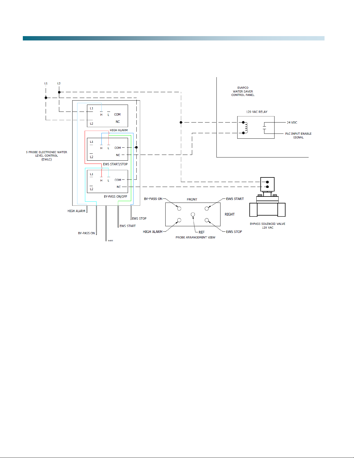
EWS Bypass Loop
The bypass engages when the water reaches the “By-Pass On” probe of the EWLC. The EWS system is designed to continue
to operate even if bypass is engaged. Maintaining inlet water pressure and flow during bypass is important.
Install bypass piping around the EWS (piping and valve by others) using the following recommendations.
xThe bypass line shall be separate to the makeup line going to the EWS and the EWS clean outlet line
xBypass piping diameter shall be equal to or smaller than Inlet (Supply) piping diameter
xIn most applications, the recommended cycle time for the bypass valve is 15-25 seconds (line size and pressure may affect
recommended cycle time)
xOn the outlet side, the bypass line must run all the way to the tower for configurations without a makeup tank
See Figure 5-Figure 7 for examples of typical bypass piping configurations. Wire the bypass valve to the 5 probe EWLC as
shown in Figure 14. Bypass operation is controlled by EWLC.
Wiring Power to the Control Panel
The EWS has the following electrical options:
1. 230V, 3 phase, 3 wire (delta)
2. 480V, 3 phase, 4 wire (wye)
Refer to Figure 13A - C for supply voltage connections.
Figure 13A: Supply Voltage 230V, delta
Figure 13B: Supply Voltage 480V, wye Figure 13C: Neutral 480V, wye
Ground
L1 L2 L3
Ground
Neutral
L1 L2 L3
13
Field Installation Guidelines (Continued)
Wiring the EWLC and Bypass Solenoid
Figure 14 shows wiring for a single EWS running off a single EWLC. Internal wiring to be done by others. For other
configurations, please contact your local Evapco Representative.
Figure 14: EWLC Wiring Diagram for a Single EWS Running off a Single EWLC

14
Figure 15 depicts the sensors, valves, and other components on the side of the EWS.
Figure 15: EWS Components
Components
Clean Outlet
Valve
Flush Outlet
Valve
Pressure
Sensor
Magnetic Flow
Meter
Sample Port
Inlet
Conductivity
Probe
Clean Outlet
Water Meter
Outlet
Conductivity
Probe
CIP Inlet
Flow Control
Valve
Pressure
Regulator
Valve
Main Inlet
Isolation
Valve
Drain Isolation
Valves
Makeup (Inlet)
Water Meter
CIP Outlet

15
Components (Continued)
Water Flow Path
Figure 16A-Figure 16B show the water flow path through the EWS. The green dotted arrows show the ion reduced (clean outlet)
water path, and the blue dashed arrows show the makeup (inlet) path.
Figure 16A: EWS Water Flow Path (Cylinder Plumbing)
Figure 16B: EWS Water Flow Path (Inlet/Outlet Piping)
Control Panel
Flush (Outlet) Water
Ion Reduced (Clean
Outlet) Water
Makeup (Inlet) Water
Flush (Outlet) Water
Ion Reduced (Clean
Outlet) Water
Makeup (Inlet) Water
16
Components (Continued)
Pressure Regulator Valve
The valve has been preset at the factory to 45 psi. Inlet supply pressure for your location may require field adjustment of the
regulator valve to achieve desired flow rate. This shall be discussed with the Factory Authorized Service Provider and approved
by EVAPCO to avoid damage to the system. Clean outlet flow rate directly correlates to inlet pressure and flow. Minimum inlet
pressure is 65 psi. Do not exceed 120 psi inlet pressure.
Water Meters
Meter is installed horizontally with register facing up. N/O reed switch set at 10 gallons per count is mounted on the dial face and
connected to the control panel.
Conductivity Probe
The EWS comes with an Inlet Conductivity Probe and an Outlet Conductivity Probe. See maintenance requirements in Table 4.
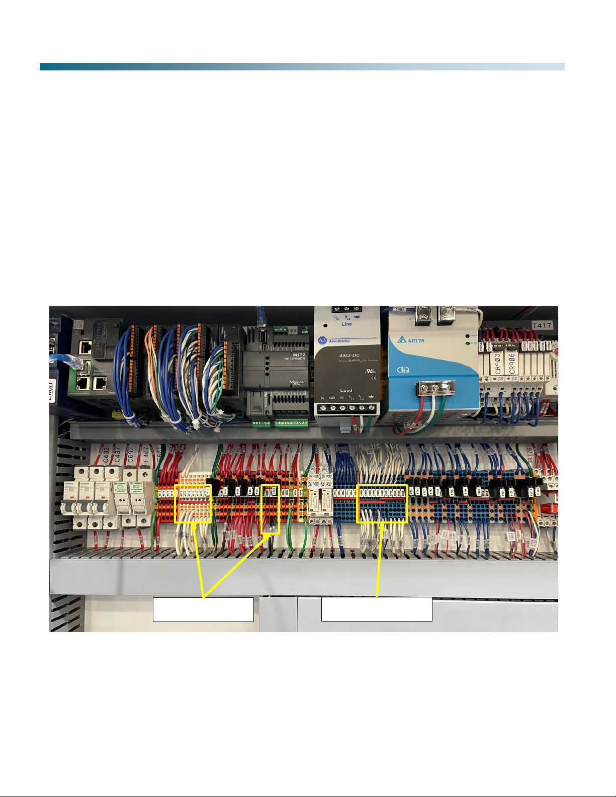
Panel Wiring Locations
In Figure 17, Valve Connections refer to the “Flush Output” and “Clean Output” solenoid valves. Sensor Connections refer to the
Inlet and Outlet Conductivity Probes, the Water Pressure Sensor, and the Inlet Flow Meter.
Figure 17: Inside Panel Wiring
Valve Connections Sensor Connections

17
The Water Saver has three sub programs.
1.
Startup program
2.
Main program
3.
Shutdown program
Each program is comprised of multiple steps. Transition from program to program and step to step is controlled by the PLC.
Programming of individual steps is performed at the factory.
Startup Program
The purpose of Startup is to prepare the cylinder’s conducting capacitors for ion removal. Once Startup program has completed,
the PLC automatically engages the Main program.
Main Program
The Main program supplies ion reduced makeup water to a tank or directly to the evaporative unit’s cold-water basin. The Main
program loops through a series of steps. The two primary steps in the Main program are “Clean” and “Flush”. During the “Clean”
step, ions are removed as water flows through the cylinders. Reduced ion water is directed to the makeup tank or directly to the
evaporative cooling unit. To maintain efficient ion removal, collected ions must be periodically purged. “Flush” step(s) purge the
collected ions. Water flow during the “Flush” step(s) is directed to drain. Other steps are also part of the Main program. These
steps maximize “Clean” water recovery. The Main program repeats until a stop signal is received.
Shutdown Program
The purpose of the Shutdown program is to prepare the superconducting capacitors for Standby status once water demand has
been satisfied. The Shutdown program consists of multiple steps to purge collected ions from the superconducting capacitors. The
Shutdown program automatically engages when the Water Saver receives a signal from the EWLC that water demand has been
satisfied. Once Shutdown steps are complete, the Water Saver awaits a signal to restart (Standby). If a start signal is received by
the Water Saver during the Shutdown steps, the Shutdown program will complete before the Water Saver restarts.
Five-Probe Electronic Water Level Control
Electronic water level control device has five probes and an electrical enclosure. The probes are threaded into connections of
the enclosure. Probes are connected to relay cards that control the operation of the Water Saver and bypass valve.
Water level is sensed in the makeup tank or evaporative unit by the probes. Each probe has a unique length. One probe is used
as reference. Reference probe tip is always submerged. When the tips of the reference and another probe are submerged, an
electrical circuit is completed resulting in a change of relay status. The water level in the tank triggers action of the devices
connected to the level sensor control.
Makeup Tank Size
(gal) [ltr]
Ref Length (in)
[mm]
Bypass On Length
(in) [mm]
EWS Start Length
(in) [mm]
EWS Stop Length
(in) [mm]
High Alarm Length
(in) [mm]
300 [1136] 77 [1956] 62 [1575] 50 [1270] 16 [406] 12 [305]
500 [1893] 59 [1499] 47 [1194] 38 [965] 16 [406] 12 [305]
750 [2839] 89 [2261] 71 [1803] 54 [1372] 17 [432] 13 [330]
850 [3218] 103 [2616] 79 [2007] 63 [1600] 17 [432] 13 [330]
1500 [5678] 101 [2565] 83 [2108] 63 [1600] 19 [483] 15 [381]
2000 [7571] 108 [2743] 105 [2667] 78 [1981] 21 [533] 17 [432]
2500 [9464] 73 [1854] 66 [1676] 51 [1295] 24 [610] 20 [508]
Table 3: EWLC Probe Lengths
Operation
18
Operation (Continued)
EWS Start/Stop
When the water level drops and the EWS START electrode is completely exposed a signal is sent to the EWS to begin
operation. EWS operation continues until the tip of the EWS STOP probe is submerged.
Note: EWS responds to electronic water level control signals only when in Automatic Mode
EWS Bypass
In the event the EWS cannot keep up with water demand, makeup water will flow through the bypass to maintain evaporative
cooling system operation. Bypass valve will open (powered) if the water level falls below the “Bypass On” probe tip. The bypass
valve remains open until water level rises to the EWS Start probe.
Note: Bypass water has not been treated by the EWS and may affect desired cycles of concentration
Hi Level Alarm (By Others)
The 5-probe EWLC is equipped with a high-water level relay and probe. High water level is sensed when the high alarm probe
tip is submerged. The high alarm relay can be connected to a user supplied device such as a warning light or audio alarm.
Note: Refer to Troubleshooting section if high level alarm frequently occurs
Touch Screen Display
A backlit LCD touch screen is mounted under a protective cover on the Water Saver Control Panel. The screen displays
operating status and data. Select the desired item by pressing the icon on the screen.
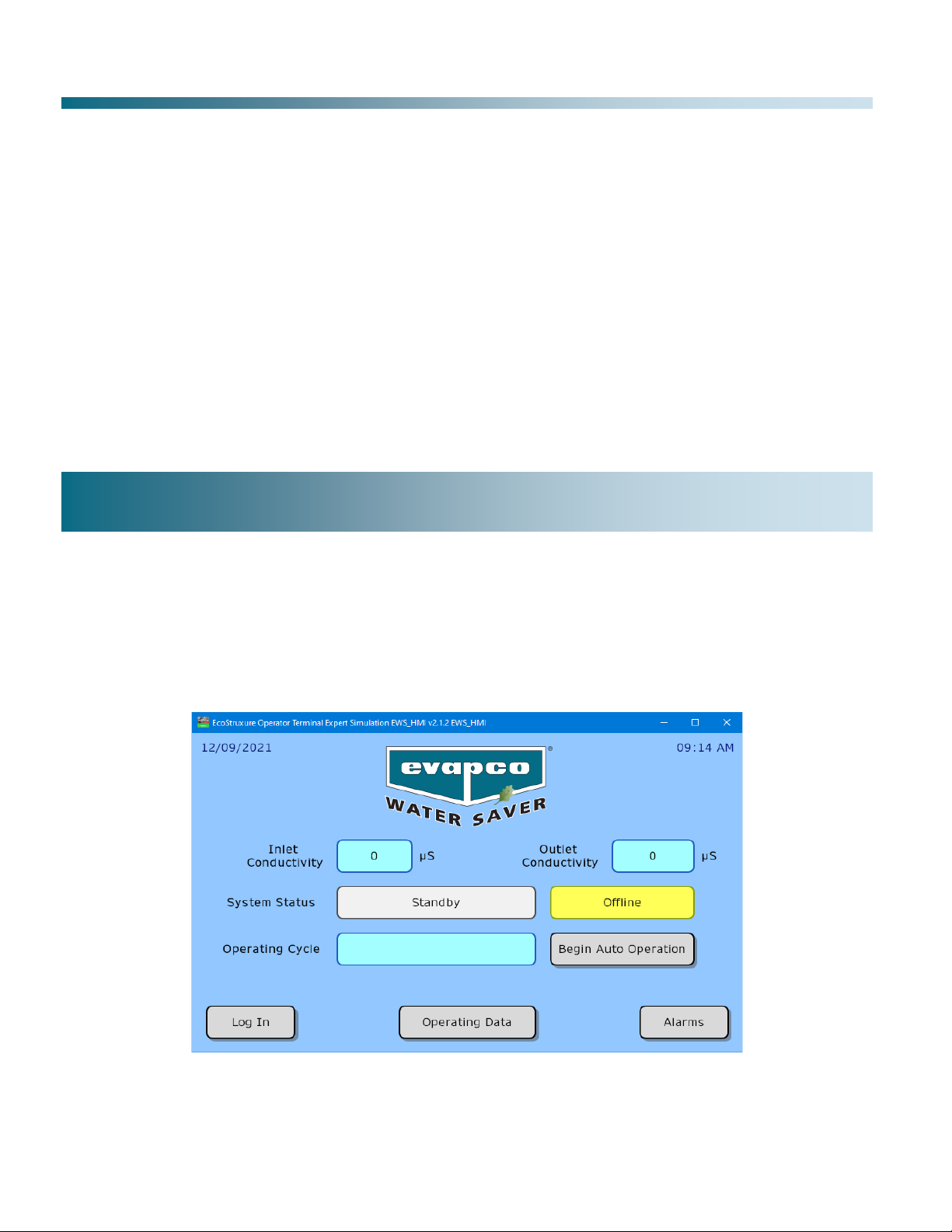
Home Screen
The Home Screen displays the present operating mode (Auto or Manual), current operating status (Operating, Standby), and
Active program. The display also provides icons to view other screens.
Figure 18: Sample Home Screen
User Display

19
User Display (Continued)
Operating Data Screen
The Operating Data screen can be accessed from the bottom center of the home screen. No login is required to access the
data. It shows conductivity, ion reduction, recovery, water meter, operating mode, system status, and valve status. Return to the
home screen by hitting the “Back” button at the bottom right.
Figure 19: Sample Operating Data Screen
Alarms Screen
The Alarms screen displays alarm history. When an alarm condition occurs a pop-up window alerts the user of a new alarm. To
acknowledge a current Alarm, select the “Acknowledge” icon. The new alarm is added to the Alarm History. Alarms can be reset
by selecting the “Reset” icon.
Figure 20: Sample Alarm Overview Screen
Alarm Configuration
Alarms are preset from the factory for seven operating attributes to alert users of system changes or equipment malfunction: Inlet
Conductivity, Outlet Conductivity, System Pressure, Flow Rate, Water Temperature, Power Supply Current Output (Amps).
Some alarms will shut down the EWS to minimize damage to the system.

20
The EWS records system operational data and stores it on USB drive as a .csv file. Periodically a window will appear indicating
that data is being written to the drive. For most systems the USB drive has enough capacity to record operation data for 2 – 3
years.
Startup Procedure
Contact your Factory Authorized Service Provider two weeks prior to needing Water Saver startup.
Shutdown Procedures
Temporary Layup or Shutdown
The Water Saver must be flushed when it has been idle (standby) for 7 consecutive days.
Extended Layup or Shutdown
For extended periods of inactivity (seasonal) EWS plumbing and cylinders should be flushed to prevent fouling. Cylinders must
be kept wet during layup. DO NOT drain or layup the system dry. Damage to cylinders may result. Contact your Factory
Authorized Service Provider to arrange for extended layup treatment.
Turning Off Power to EWS
To turn off the Water Saver, perform the following:
x
Move the service disconnect handle on the Control Panel to the OFF position
Restarting Power
To restart the Water Saver, perform the following:
x
Move the service disconnect handle on Control Panel to the ON position.
x
Wait for the Home screen to be displayed (~ 20 seconds)
x
Place system in Automatic Mode
o
Select “Begin Auto Operation” icon
Routine maintenance is required to maintain EWS system performance over time. Keep panel, piping and components clean by
wiping with a soft damp cloth, as needed. Do not use solvents or cleaners unless directed.
Description
Service Interval
Control Panel Air Filter Cleaning Quarterly or as needed
Pressure Regulator Valve Cleaning Quarterly or as needed
Inlet Water Meter Cleaning Quarterly or as needed
Outlet Water Meter Cleaning Quarterly or as needed
Verify In-Line Conductivity Probes Monthly
Conductivity Probe Calibration Quarterly or as needed
Clean in Place (CIP) Every 2-4 months
Table 4: Maintenance Requirements
Data Logs
Startup and Shutdown
Maintenance
This manual suits for next models
8
Table of contents
Popular Water System manuals by other brands


Everpure
Everpure QL2-OCS2 Specification sheet

DIG
DIG ST100AS installation instructions

Zip
Zip HydroTap G5 Touch-Free Wave installation instructions

Daikin
Daikin EKSV21P Planning and installation instructions

Halsey Taylor
Halsey Taylor HBW8AQ 1M Series manual

Spectra Watermakers
Spectra Watermakers Newport MkII Deluxe installation instructions


