manuals.online logo
Brands
  1. Home
  2. •
  3. Brands
  4. •
  5. Halsey Taylor
  6. •
  7. Water System
  8. •
  9. Halsey Taylor HBW8AQ 1M Series User manual

Halsey Taylor HBW8AQ 1M Series User manual

98591C (Rev. B - 10/10)PAGE1
HBW8AQ*1M HBW8AQ*2M HBW*M*L*R
HALSEYTAYLOROWNERS MANUAL
USESHFC-134AREFRIGERANT
FIG. 1
8, 9
SEEFIG. 4
SEEFIG.3
21
18
33
16
17
22
6
31
10
3, 4, 5
7
11
12
30
32
2
19
1
13, 14, 15 20
34
35, 36, 37
SEE
DETAIL
ABOVE 39
NOTE: Non-refrigerated units do not include all electrical and refrigeration components shown above.
Other components and rough-in are the same as shown.
29
38
41
40
98591C (Rev. B - 10/10) PAGE2
HBW8AQ*1M HBW8AQ*2M HBW*M*L*R
C
L
6"
152mm
9 1/2"
241mm
3 1/2"
89mm 18"
457mm
20 1/4"
514mm
16 3/4"
425mm
40"*
1016mm
6 3/8"
162mm 6 3/8"
162mm
2 5/8"
67mm
18 3/4"
476mm
1"
25mm
1 1/2"
38mm
3/4"
9mm
1 1/2"
38mm
3/4"
9mm
5 1/4"
140mm
4"
102mm
3"
76mm
23 1/2"
597mm
24"
610mm
26"
660mm
E
E
C
D
B
A
G
F
3 1/4"
83mm 3 1/4"
FIG. 2
* RECOMMENDED HEIGHT FOR ADULTS.
DECREASE HEIGHT FOR CHILDREN.
* ALTURA RECOMENDADA PARA ADULTOS. REDUZCA
PARA LOS NIÑOS.
* HAUTEUR RECOMMANDÉE POUR LES ADULTES.
INSTALLEZ PLUS BAS POUR LES ENFANTS.
FINISHED FLOOR
PISOACABADO
PLANCHERFINI
LEGEND/LEYENDA/LÉGENDE
A= RECOMMENDED WATER SUPPLY LOCATION 3/8 O.D. UNPLATED COPPER TUBE CONNECT STUB 1-1/2 IN. (38 mm) OUT FROM WALL SHUT OFF BY
OTHERS
SE RECOMIENDAUBICAR ELTUBO CORTO DE CONEXIÓNALTUBO DE COBRE SIN CHAPAR DE 3/8" DE DIÁM. EXT.A1-1/2" (38 mm) FUERA DE LALLAVEDE
PASO EN LAPAREDCOLOCADAPORTERCEROS.
EMPLACEMENT RECOMMANDÉ D'ALIMENTATION EN EAU PARTUBE EN CUIVRE NON PLAQUÉ DE 3/8 PO. (9,5 mm) D.E. CONNECTANT UNE TUYAUTERIE DE
1-1/2PO. (38 mm)DEPUIS LE ROBINETD'ARRÊTFOURNI PAR D'AUTRES.
B = RECOMMENDED LOCATION FOR WASTE OUTLET 1-1/4” O.D. DRAIN
UBICACIÓN RECOMENDADAPARA ELDRENAJE DE SALIDADEAGUA, DE 1¼” DE DIÁMETRO.
EMPLACEMENTRECOMMANDÉ POUR LEDRAIN DE D.E.1-1/4"DE SORTIE D’EAU.
C = 1-1/4 TRAP NOT FURNISHED**
PURGADORDE 1¼ NOPROPORCIONADO**
SIPHON1-1/4 NON FOURNI**
D = ELECTRICAL OUTLET LOCATION
UBICACIÓNDE LA TOMADE ELECTRICIDAD
EMPLACEMENTDE LA PRISEDECOURANT
E = INSURE PROPER VENTILATION BY MAINTAINING 4" (102mm) (MIN.) CLEARANCE FROM CABINET LOUVERS TO WALL.
ASEGUREUNAVENTILACIÓNADECUADAMANTENIENDO UNESPACIO E4"(102mm) (MÍN.) DEHOLGURAENTRE LAREJILLADEVENTILACIÓN DELMUEBLE Y
LAPARED
ASSUREZ-VOUSUNE BONNE VENTILATION ENGARDANT4"(102mm) (MIN.) ENTRELES ÉVENTS DEL’ENCEINTEETLE MUR.
F = POWER CORD 1-1/2FEET (457mm) LONG
CABLEELÉCTRICO DE 1½ PIE,457 mmDELARGO
CORDOND’ALIMENTATION1-1/2' (457mm)
G = 5/16" (8mm) SCREW HOLES IN MOUNTING PLATE
AGUJEROSDETORNILLO5/16"(8mm) EN LAPLACADE MONTAJE
TROUSDE VIS 5/16"(8mm)DANS LAPLAQUE DEMONTAGE
98591C (Rev. B - 10/10)PAGE3
HBW8AQ*1M HBW8AQ*2M HBW*M*L*R
FIG. 3
Stream height is factory set at 35 PSI. If supply pressure varies greatly from this,
remove items 23 and 24 and adjust screw on item 26. Clockwise adjustment will raise stream
and counter-clockwise adjustment will lower stream. For best adjustment, stream should hit
basin approximately 6-1/2" (165mm) from bubbler.
IMPORTANT
ALLSERVICETOBEPERFORMEDBYANAUTHORIZEDSERVICEPERSON
HANGERBRACKETS &TRAP INSTALLATION
1) Remove hanger brackets fastened to back of cooler by removing screws.
2) Mount the hanger brackets and trap as shown in Figure 2.
NOTE: Hanger Brackets and trap MUST be supported securely. Add fixture support carrier if wall will not provide adequate
support.
IMPORTANT:
- 5-1/2 in. (140mm) dimension from wall to centerline of trap must be maintained for proper fit.
- Anchor hanger securely to wall using all mounting holes.
3) Install straight valve for 3/8" O.D. unplated copper tube.
INSTALLATION OFCOOLER
4) Hang the cooler on the hanger brackets. Be certain the hanger brackets are engaged properly in the frame and wrapper.
5) Remove the access panel on the underside of the cooler and set it aside.
6) Connect water inlet line--See Note 4 of General Instructions.
7) Remove the slip nut and gasket from the trap and install them on the cooler waste line making sure that the end of the waste
line fits into the trap. Assemble the slip nut and gasket to the trap and tighten securely.
START UP
Also See General Instructions
8) Replace the front panel and secure by retightening all screws.
CORRECTSTREAM HEIGHT
FIG. 4
WRAPPER
26
24
25
23 27 28
98591C (Rev. B - 10/10) PAGE4
HBW8AQ*1M HBW8AQ*2M HBW*M*L*R
ITEMIZED PARTS LIST
ITEMNO. PARTNO. DESCRIPTION
36208C
27095C
30664C
70018C
31490C
70009C
56237C
51544C
56159C
66743C
66703C
36094C
36158C
35768C
35959C
66576C
45871C
26664C
75536C
35839C
66810C
55996C
40089C
40048C
15005C
61313C
40169C
50986C
40575C
27093C
28797C
27097C
27094C
See Color Table
50144C
70184C
70418C
50074C
70817C
20430C
20415C
56092C
Power Cord
Fan Bracket
Fan Blade
Hex Nut - Fan Blade
Fan Motor
Screw (Fan Motor)
Shroud - Fan
Bubbler
Nipple - Bubbler
Condenser
Drier
Compressor Serv. Pak EMI 70 HNR
Overload
Cover - Relay
Relay
Heat Exchanger
Tailpipe
Basin - Stainless Steel
Screw - Basin Mtg.
ColdControl
Evaporator Assembly
Strainer
Cover
Button
RetainingNut
Regulator
Hex Nut
Regulator Holder
Strainer & Ferrule Assy
Angle - Front Corners
Bracket - Basin Mounting
Frame - Back/Bottom
Bracket - Front
Wrapper
Grommet - Compressor Mtg
Hair Pin - Cotter
Washer
Tailpipe - Gasket
Fitting - Elbow 1/4 Stem
Hanger - Bracket
Hanger - Bracket
Poly Tubing (Cut to Length)
1
2
3
4
5
6
7
8
9
10
11
*12
13
14
15
16
17
18
19
20
21
22
23
24
25
26
27
28
29
30
31
32
33
34
35
36
37
38
39
40
41
NS
*INCLUDESRELAY&OVERLOAD. IFUNDERWARRANTY,
REPLACEWITHSAMECOMPRESSORUSEDINORIGINAL
ASSEMBLY.
NOTE: All correspondence pertaining to any of the above
water coolers or orders for repair parts MUST include Model
No. and Serial No. of cooler, name and part number of re-
placement part.
COLOR TABLE
PANELCOLOR Item No.34
PartNo.
Almond Vinyl
PlatinumVinyl
Stainless Steel
Slate Vinyl
21481C
26943C
21013C
26949C
2222CAMDEN COURT
OAKBROOK, IL60523
630.574.3500
PRINTEDINU.S.A. FORPARTSCONTACTYOURLOCALDISTRIBUTORORVISITOURWEBSITEWWW.HALSEYTAYLOR.COM
220V 50Hz
35827C
31430C
36085C
36195C
36050C
35826C
Power Cord
Fan - Motor 4w 230V 50/60 Hz
Compressor Serv. Pak EM 65 220V
Overload
Relay
Power - Inlet
PART. NO. DESCRIPTIONITEMNO.
1
5
*12
13
15
-

This manual suits for next models

2

Other Halsey Taylor Water System manuals
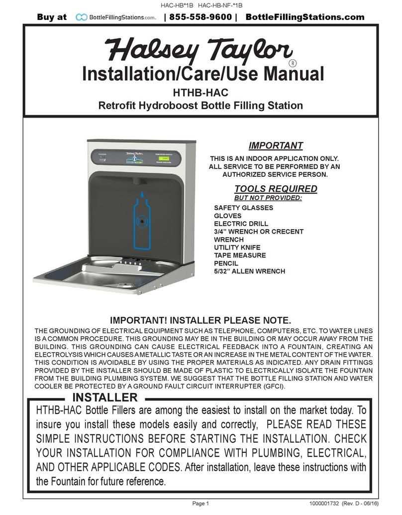
Halsey Taylor HTHB-HAC Installation manual
Halsey Taylor

Halsey Taylor HTHB-HAC Installation manual

Halsey Taylor HVRGRN8WSNF 1C Series User manual

Halsey Taylor

Halsey Taylor HVRGRN8WSNF 1C Series User manual

Halsey Taylor S300-2EQ 1N Series User manual

Halsey Taylor

Halsey Taylor S300-2EQ 1N Series User manual

Halsey Taylor WCFS G L R Series User manual

Halsey Taylor

Halsey Taylor WCFS G L R Series User manual

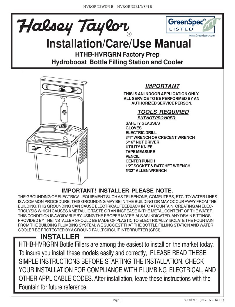
Halsey Taylor GreenSpec HTHB-HVRGRN Installation manual

Halsey Taylor

Halsey Taylor GreenSpec HTHB-HVRGRN Installation manual

Halsey Taylor HTVZD*1C series User manual

Halsey Taylor

Halsey Taylor HTVZD*1C series User manual

Halsey Taylor HOF14A-FR-Q 1D Series User manual

Halsey Taylor

Halsey Taylor HOF14A-FR-Q 1D Series User manual

Halsey Taylor HydroBoost HTHBSM-1A Instructions for use

Halsey Taylor

Halsey Taylor HydroBoost HTHBSM-1A Instructions for use

Halsey Taylor HOF14AFRQ 1F Series User manual

Halsey Taylor

Halsey Taylor HOF14AFRQ 1F Series User manual

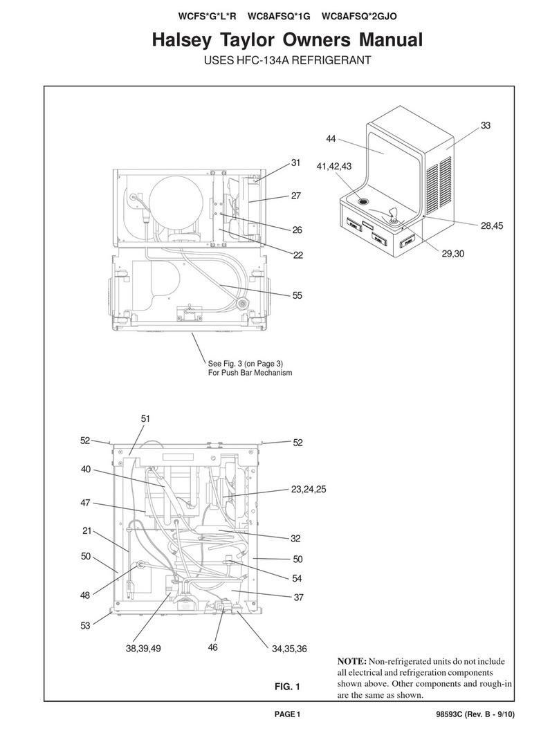
Halsey Taylor HVRGRN8WSNF 1B Series Installation manual
Halsey Taylor

Halsey Taylor HVRGRN8WSNF 1B Series Installation manual

Halsey Taylor HTVZDBL*1C series User manual

Halsey Taylor

Halsey Taylor HTVZDBL*1C series User manual

Popular Water System manuals by other brands

H2O USRO4-50-JG Installation and service guide

H2O

H2O USRO4-50-JG Installation and service guide

VERIPURE VERIPUREVPC5000 owner's manual

VERIPURE

VERIPURE VERIPUREVPC5000 owner's manual

Cattron Aquavx quick start guide

Cattron

Cattron Aquavx quick start guide

Rinnai INFINITY 26 installation manual

Rinnai

Rinnai INFINITY 26 installation manual

Julabo 9021713.S1.02 Original operating manual

Julabo

Julabo 9021713.S1.02 Original operating manual

iDM HYGIENIK 2.0 Installation instruction

iDM

iDM HYGIENIK 2.0 Installation instruction

Armstrong 3760 Pro Series Installation and operating instructions

Armstrong

Armstrong 3760 Pro Series Installation and operating instructions

aarke CARBONATOR 3 user guide

aarke

aarke CARBONATOR 3 user guide

Leaksafe Solutions WaterSwitch3 installation instructions

Leaksafe Solutions

Leaksafe Solutions WaterSwitch3 installation instructions

Sears 390.250095 owner's manual

Sears

Sears 390.250095 owner's manual

Waterite VECTAMAXX RSR Operator's manual

Waterite

Waterite VECTAMAXX RSR Operator's manual

Graf EcoBloc Inspect flex manual

Graf

Graf EcoBloc Inspect flex manual

Fisherbrand Accu100 instruction manual

Fisherbrand

Fisherbrand Accu100 instruction manual

Craftsman 390.252156 owner's manual

Craftsman

Craftsman 390.252156 owner's manual

Badeloft AT-05 installation instructions

Badeloft

Badeloft AT-05 installation instructions

Expondo UNI_WATER_05 user manual

Expondo

Expondo UNI_WATER_05 user manual

Taco Comfort Solutions 2400 Series instruction sheet

Taco Comfort Solutions

Taco Comfort Solutions 2400 Series instruction sheet

Armstrong E.2 Series Installation and operating instructions

Armstrong

Armstrong E.2 Series Installation and operating instructions

manuals.online logo
manuals.online logoBrands
  • About & Mission
  • Contact us
  • Privacy Policy
  • Terms and Conditions

Copyright 2025 Manuals.Online. All Rights Reserved.