evenes Gelbi D 4.2 User manual
Operating manual and assembly
Air / Water Heat Pump
Version: 4_07_2020

2

3
1. Description of the Heat Pump ............................................................................................................................. 4
2. Construction of the Heat Pump .......................................................................................................................... 4
3. Installin of the Heat Pump ................................................................................................................................ 4
4. Description of controller functions ..................................................................................................................... 8
5. Main menu .......................................................................................................................................................... 9
6. Fitters menu ...................................................................................................................................................... 11
7. Service menu ..................................................................................................................................................... 15
8. Standby mode ................................................................................................................................................... 19
9. Security and Alarms .......................................................................................................................................... 20
10. Maintenance ................................................................................................................................................... 22
11. SG Ready function ........................................................................................................................................... 22
12. The procedure after the shelf life of the device.............................................................................................. 22
13. Electrical dia ram ............................................................................................................................................ 23
14. Hydraulic dia rams .......................................................................................................................................... 25
15. Technical data ................................................................................................................................................. 28
Start-up protocol of the heat pump GELBI D4.2 .................................................................................................. 30
Start-up protocol of the heat pump GELBI D4.2 ................................................................................................... 31
4
1. Description of the Heat Pump
Heat pump GELBI D4.2 is a device desi ned for preparation domestic hot water. It uses the rotary
screw compressor optimised for hi h condensation temperatures, i.e. enablin heatin to hi h
temperature. The air flow is forced via the finned coil by modern, powerful and ener y efficient fan.
Water is heated in the SWEP plate exchan er made of stainless steel. Hot water circulation is forced
by WILO circulatin pump adapted also to work directly with tap water. The correct operation of the
heat pump is supervised by a controller with an al orithm optimised for the desi n of the GELBI D4.2
heat pump. The housin is made of ABS plastic. All the above mentioned characteristics and
components comprise the hi h quality and efficiency of the heat pump.
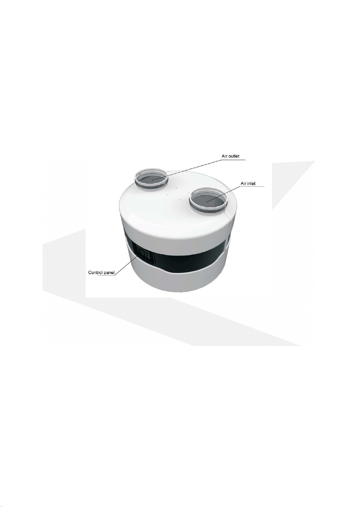
2. Construction of the Heat Pump
Power supply cord and tank and buffer sensor are located at the back of the device.
. Installing of the Heat Pump
.1 Precautions during installation of the device
Installation of the heat pump should be performed by a person with appropriate qualifications in the
field of heatin and coolin devices. The country-specific health and safety re ulations must be
observed durin installation.
.2 Installation recommendations
GELBI D4.2 heat pump should be installed in a room where the temperature does not drop below +
5°C. If the temperature may fall below +5°C, the water circuit between the heat pump and the
stora e tank must be emptied and the system has to be blown out well, e. . with compressed air.
During the installation process heat pump should be levelled by adjusting height of the legs. Failure
to comply with this recommendation may result in a defective work and eventually damage to the
equipment.

5
Keep a distance from the barriers (ceilin walls, etc.) for trouble-free maintenance of the heat pump.
In the bottom part of the heat pump housin there is a condensate drain connection to which the
drain hose must be connected. It is recommended to drain the condensate into the sewa e system
and to use a siphon.
. Connection of hydraulic circuit
The heat pump has a built-in automatic air vent that ensures ventin of the condenser and the
heatin loop.
The pipeline between the heat pump and the stora e tank must have an internal diameter of 20 mm.
The heat pump must be connected to the system via flexible hoses.
On the return pipe line install the strainer filter !!!
The pipelines should be insulated on the whole len th!!!
.4 Connection of air ducts
The heat pump has two connections for connectin the air ducts. The internal diameter of the air
ducts should be min. 250 mm. It is recommended to install insulated air ducts. The maximum
len ths of the air ducts: 8m
Note:
- The use of smaller diameter air ducts may result in a decrease in efficiency.
- When connecting air ducts outside the building, it is essential to provide protection
against air circulation in winter (sub-zero temperatures) when the heat pump is out of use.
A coarse ISO filter (ISO Coarse) in accordance with the current ISO 16890 or a G2 class filter
(compatible with the withdrawn standard EN 779: 2012) should be installed on the heat pump
suction duct.
NOTE !!!
•The temperature difference between supply and return of heating circuit should be
set 5-8K
•The heat pump should be connected to the power supply at all times. This applies
when the DHW tank is heated by another heat source. The controller should be in
standby mode. All protective functions are then carried out: condenser protection,
antifreeze protection: DHW and buffer tank, pump antistop function.
6
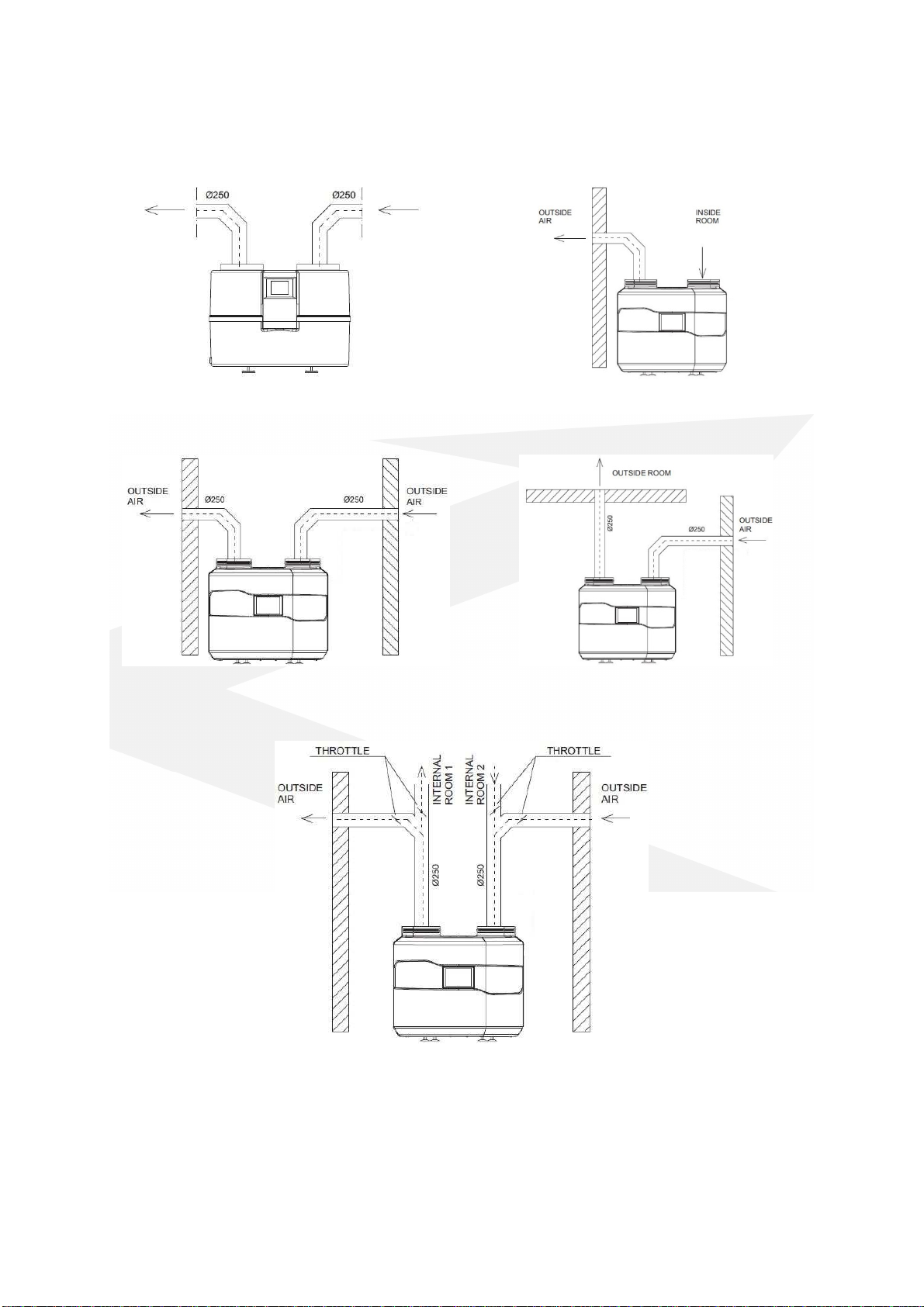
Air extracted from one room and exhausted to
another room
Air extracted from one room and exhausted
throu h the wall to another room
Air extracted from the outside throu h the wall
and exhausted to the outside throu h the wall
Air extracted
from the outside throu h the wall
and exhausted to the outside throu h the roof
Separation of inlet and exhaust air
Heat pump cooperatin with recuperator
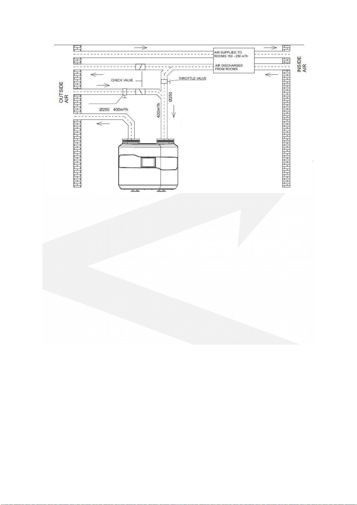
7
The heat pump and the recuperative unit operate independently of each other, therefore the
ventilation ducts should also be separated. This means that when the recuperation is workin and
the heat pump is stopped, then the air flows easily to the ventilation outlet and not to the heat
pump. This would reduce the efficiency of the recuperative air handlin unit fan.
Note: In addition, the intake and ejection of air from the room in which the pump is installed is
permitted. However, this may lead to a reduction in ener y efficiency.
.5 Electrical connection
The heat pump is powered by 1~230V/50 Hz. As a standard it has a plu with a cable of 1.5 m len th.
Important: It is recommended that the electric supply circuit of the heat pump was equipped in the
circuit breaker with characteristic "C" and residual current device with rated differential current
transmission of 0.03A.
Note: All work related with the installation of these elements should be performed by personnel with
the appropriate permissions and qualifications. As a standard there is a possibility of connectin
electric heater up to 1.5 kW. If electric heater with more power is needed, replace the existin power
supply cable.
The sensor cable can be extended up to 5m.
For its extension can be used e. . cable type H03VVV-F 2x0.5mm^2 or with similar parameters.
If the heat pump controller does not work, first check the fuse on the heat pump supply circuit and
then the fuse placed on the control board inside the heat pump. For this purpose, the heat pump
housing must be partially removed.
8
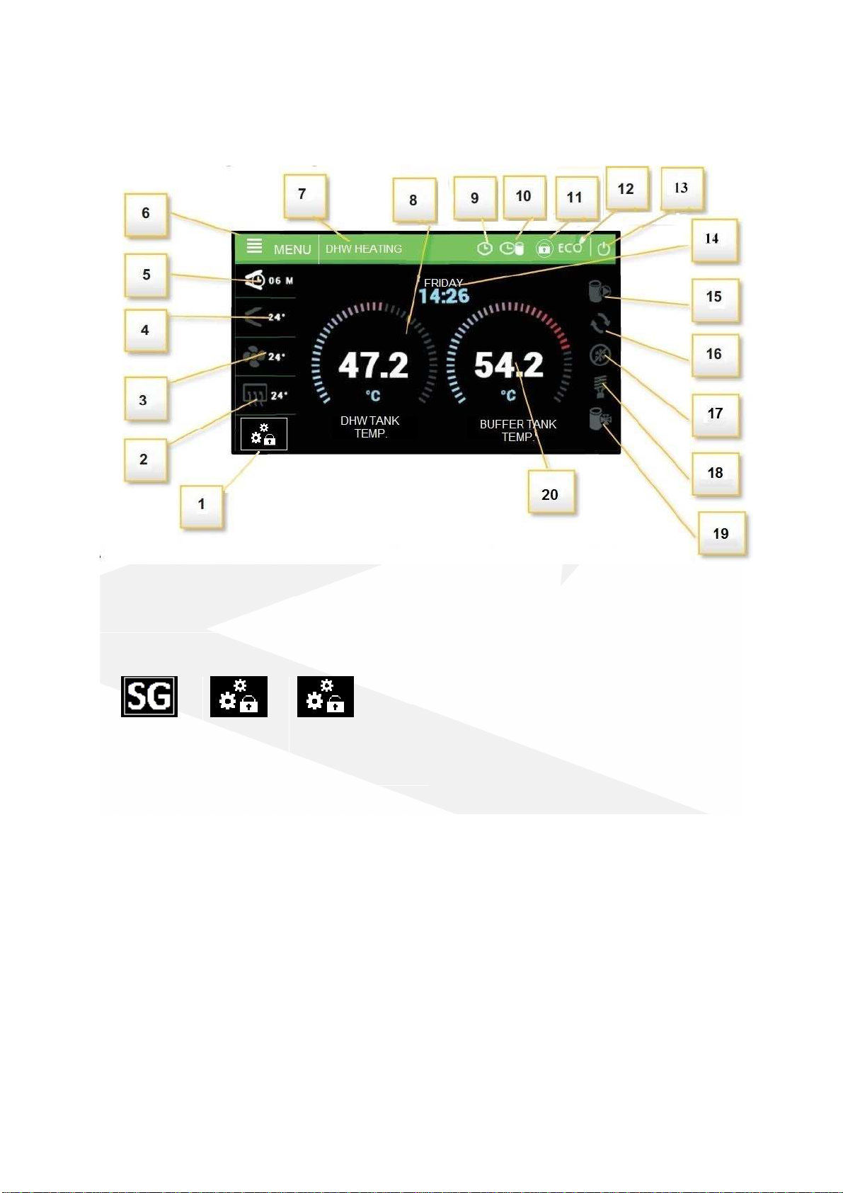
4. Description of controller functions
Description of icons displayed in the controller in the operatin mode:
1
-
Operatin mode of the additional
contact:
9
-
Active weekly schedule of the DHW
10- Active weekly schedule of buffer heatin
11- Active controller lock
12- ECO / ECO PLUS mode
13- STANDBY mode icon
14- Day of the week and current time
15- Operatin status of the tank pump
16- Operatin status of the circulation pump
17- Operatin mode status - "defrost"
18- Operatin status of the heater
19- Operatin status of the buffer pump
20 - Current DHW tank temperature (for
operation with heat buffer, the temperature
measured in the buffer tank)
Active SG
function
End of
heatin by
thermostat
Heatin option
with active
thermostat
2
-
Evaporator temperature
3- Outdoor temperature and fan operation
indication
4- Hot as control temperature and indication of
compressor operation
5- Time to restart the compressor
6- Enter to the controller menu
7- Heat pump mode, alarm notifications
8- Current DHW tank temperature
4.1 Control of the work of executive equipment
The controller controls the operation of the compressor, fan, inte rated circulation pump, circulation
pump and electric heater. The compressor is activated with a delay in relation to the circulation
9
pump and fan – delay compressor parameter. The electric heater operates above ECO-PLUS
temperature, in Party mode and in case of failure.
Attention: The heater is not installed in the device. It is an optional external component, which can
be controlled by the heat pump controller.
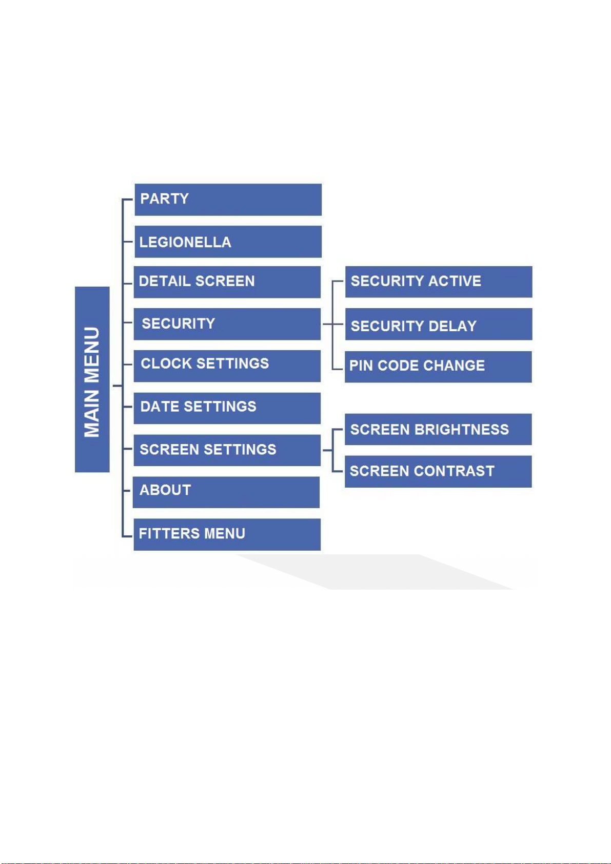
5. Main menu
5.1 Party
When Party mode is activated, the heat pump tank reaches the set temperature as soon as possible.
In this mode, all available heat sources connected to the controller operate simultaneously.
5.2 Legionella
When this function is activated, the boiler heats up to 70°C (factory settin ) and maintains this
temperature for a specified period of time, then returns to normal operation. Any chan es to the
settin s for this function are only possible in the service menu.
5. Detail screen
The detailed screen shows the temperatures measured by the sensors and the status of the pressure
switches.

10
5.4 Security
5.4.1 Security active
Driver blocks access to functions in the controller menu after a defined period of inactivity.
Prevents settin chan es by unauthorized persons or children.
5.4.2 Security delay
If the option Security active is selected, the controller blocks access to the functions of controller
menu after a specified period of inactivity (settin security delay). In order to unblock the controller it
is necessary to enter a four-di it code, which can be defined in the option PIN code change.
5.4. PIN code change
The user sets his own PIN code to the controller.
5.5 Clock setting
Settin the current time in the controller.
5.6 Date setting
Settin the current date in the controller.
5.7 Screen settings
5.7.1 Screen brightness
Screen bri htness settin s.
5.7.2 Screen saver brightness
Set the bri htness level of the screen saver.
5.8 About
The function allows the user to preview the controller information - name of the manufacturer,
software number, and service telephone number.

11
6. Fitters menu
6.1 DHW tank set. temperature
This function is used to set the tank set-point temperature. The fan, compressor and pump run until
the set tank temperature is reached.
6.2 DHW anti-freeze
Tank anti-freeze function. It is also active in "standby" mode.
6.2.1 Anti-freeze heating source
The user selects the device (heater, heat pump) that will start to protect the tank from freezin .
Note: Please note that the heat pump can only operate at temperatures above 5°C.
The heater is optional. It can be connected to the output of the control board accordin to the
electrical scheme in the manual.
6.2.2 Anti-freeze threshold
When the temperature drops below a certain temperature threshold (factory set limit is 5°C) the
heat pump or the electric heater starts permanently. It is switched off when the tank temperature is
3°C hi her than the set parameter.
6. Buffer anti-freeze
The parameter is available only for the enabled buffer function: 6.7.1 Buffer tank active and
connected buffer sensor.

12
6. . 1 Anti-freeze threshold
When the temperature drops below a certain temperature threshold (factory set limit is 5°C) the
heat pump or the electric heater starts permanently. It is switched off when the tank temperature is
3°C hi her than the set parameter.
6.4 Schedule
When the weekly control function is activated, the heat pump will operate at the set times in
comfort mode and the rest in reduced mode. The set-point temperatures in modes are editable.
6.4.1 Weekly schedule active
This option enables / disables weekly control of the heat pump operation
Note: Weekly control will work correctly after setting the current time and date.
6.4.2 Weekly schedule
The first step in editin the weekly schedule is to select the day for which you want to specify the
settin s.
1
-
Set the Reduced temperature
2- Delete the current pro ram
3- Selection of copyin (allows you to copy
the current mode to other hours of
operation)
4- Cancel button - exit to day selection
screen
5- Set the Comfortable temperature
6- Icon for chan in the timer settin (back)
7
-
Confirm button
-
confirmation of the set
pro ram
8- Icon for chan in the timer settin
(forward)
9- Comfort mode active
10- Reduced mode active
11- Day
12- Return to home screen
After finishin the pro ram settin s, press the "Confirm" button, then you can copy the pro ram to
another day of the week. Press the "cancel" button, if you want to delete the whole pro ram from
the set day.
6.4. Temp. comfortable
The user sets the comfort temperature that the controller will maintain when it is active in the
weekly pro ram.

13
6.4.4 Temp. reduced
The user sets the reduced temperature that the controller will maintain when it is active in the
weekly pro ram.
6.5 Circulation pump
This function is used to activate the connected circulation pump and to define individual settin s. The
circulation pump operates in intermittent mode accordin to the parameters of operatin time,
break time and weekly schedule.
6.5.1 Pump active
Activation of the circulation pump.
6.5.2 Operation time
Operatin time of the circulation pump.
6.5. Pause time
Circulation pump standstill time.
6.5.4 Weekly schedule
The user sets the hours and days of the week on which the circulation pump should operate. The
weekly schedule settin is similar to the weekly pro ram settin for the DHW tank.
6.6 Set temp. SG function
The user sets the tank temperature in the SG function ( work with a photovoltaic system).
In certain conditions (openin of the SG contact) the controller will activate the Comfort mode in the
SG function re ardless of the weekly pro ram.
Note: For proper operation of the SG function, the activation of the weekly schedule is required.
6.7 Buffer tank
Control parameters for heatin the buffer tank are available in the section. The buffer tank has a
lower priority over the DHW cylinder.
6.7.1 Buffer tank active
Selectin this option activates the buffer tank heatin function. Connection of a buffer sensor is
required.
6.7.2 Buffer tank set temp.
Settin the tar et temperature of the buffer tank.
6.7. Buffer tank hysteresis
Settin the hysteresis of the buffer tank heatin .
The tank is char ed until the desired temperature is reached. Rechar in is possible when the buffer
temperature is equal to or lower than the preset temperature by the value of the set parameter.
6.7.4 Set tem SG function
In this section, the user sets the tar et temperature of the tank when the heat pump uses the ener y
enerated by the photovoltaic system.
6.7.5 Schedule
In the schedule section of the controller there are the followin parameters:
Weekly schedule active- activation of the weekly pro ramme for workin with the buffer.
Weekly schedule- the controller allows to set periods of time for each day of the week durin which
the comfortable temperature or reduced temperature in the buffer tank will be maintained. The
weekly pro ram is set in the same way as the weekly DHW schedule. (6.4.2 Weekly schedule).
Temp. comfortable- settin the comfort temperature in the buffer tank.

14
Temp. reduced- settin the reduced temperature in the buffer tank.
6.8 Ethernet module
NOTE
This type of control is possible exclusively after purchasin and connectin to the driver the
additional ST-505 module which isn't attached to the standard driver. An internet module is a device
allowin remote control of the heat pump throu h the Internet or the local network. The user
controls the operatin parameters of all devices on the screen of the personal computer (PC).
Workin parameters of every device is presented in the form of the animation. For more information
on connection and confi uration, refer to the ST-505 module manual.
6.8.1 Module on
Turnin on the Ethernet module ST-505. After activatin the parameter, further parameters related
to the module connection will appear in the controller.
6.8.2 Registration
The re istration process of the module for the Internet platform is available on htttps://emodul.pl.
After completion of re istration in the controller will display the code, which should be entered in
the re istration field (Re istration code from the controller).
6.8. DHCP
Active DHCP option will download network settin s to which ST-505 module is connected, includin :
IP address, network mask, ateway address, DNS address.
6.8.4 IP Address
Manually assi n an IP address.
6.8.5 Network mask
Manually assi n a network mask.
6.8.6 Gateway address
Manually assi n a network ateway address.
6.8.7 DNS Adress
Manually assi n a DNS address.
6.8.8 Module version
An option that displays information related to the network settin s and the software version of the
Ethernet module.
6.9 Language
This function allows you to set the lan ua e version of the controller.
6.10 Factory settings
The controller is preconfi ured for operation. However, it should be adjusted to the user needs. You
can return to the factory settin s at any time. If you switch on the factory settin s, you will lose all
your own settin s for the heat pump (saved in the user menu) to the settin s saved by the controller
manufacturer. From this point user can reset your own service parameters of the heat pump.
15
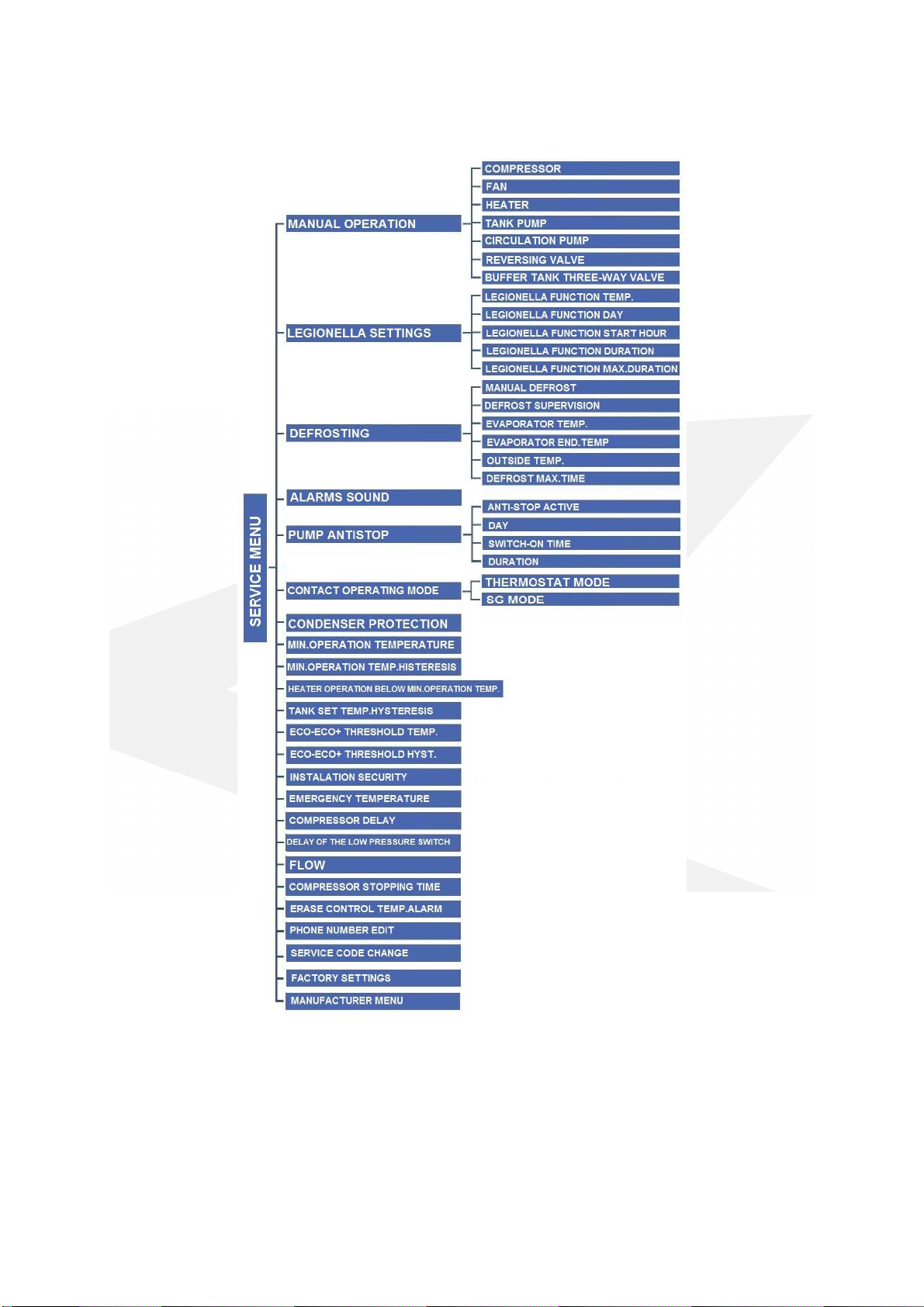
7. Service menu
To open the service menu of the controller, enter a four-di it access code.
7.1 Manual operation
The function allows to enable individual devices re ardless to other to verify its operation. Press the
appropriate icon to switch on each device.

16
7.2 LEGIONELLA settings
LEGIONELLA function is used to disinfect the tank. In the service menu the user can confi ure
individual parameters of this function.
7.2.1 LEGIONELLA function temp.
The function allows to define the set-point temperature of disinfection.
7.2.2 LEGIONELLA function day
Select the day of the week on which the Le ionella function will be executed.
7.2. LEGIONELLA function start hours
Set the start time for Le ionella function.
7.2.4 LEGIONELLA function duration
This function allows settin the duration of the disinfection (in minutes) in which the set-point
temperature of disinfection stays at a constant level.
7.2.5 LEGIONELLA function max. duration
It is the maximum total disinfection time (LEGIONELLA function) from the moment of switchin on
(re ardless of the temperature durin switchin on). If the tank does not reach the preset
disinfection temperature or does not maintain the preset temperature for the duration of the
LEGIONELLA function, the controller will return to the basic operation mode after the time set in the
LEGIONELLA function max. duration.
7. Defrosting
The defrostin process involves switchin on the compressor, circulatin pump and shiftin the
defrost valve. The defrost mode continues until the evaporator reaches the desired temperature.
7. .1 Manual defrost
Activation of the manual defrost function. This function should be used in case of emer ency (stron
evaporator frostin ). The controller will allow the defrost function to be activated when the
evaporator and external temperatures are lower than the values set in the defrost parameters.
7. .2 Defrost supervision
Activation of the low pressure control over the defrost.
7. . Evaporator temp
The controller will start defrostin automatically when the evaporator temperature is lower than the
set value.
7. .4 Evaporator end temp.
The controller will end defrostin when the temperature on the evaporator reaches the set value.
7. .5 Outside temp.
The controller will start defrostin when the external temperature is lower than the set value.
7. .6 Defrost max. time
Defrostin is limited in time. If the evaporator cannot be effectively defrosted after this time, the
heat pump oes throu h a 10-minute preheatin cycle, followed by a defrostin process a ain. After
3 unsuccessful defrost attempts, a defrost error messa e is displayed and the heat pump is blocked.
All protection functions remain active. The heat pump resets when the power is disconnected.

17
7.4 Alarms sound
Option to enable/disable the alarm si nal.
7.5 Pump anti-stop
Function to prevent " sta nation " of the built-in circulation pump. The function also works in
"standby" mode. The controller will start the circulation pump accordin to the followin
parameters.
7.5.1 Anti-stop active
Activatin anti-stop mode. This function should always be active
7.5.2 Day
Select the day of the week on which the circulation pump starts in anti-stop mode.
7.5. Switch-on time
Settin the pump switch-on time in antistop mode.
7.5.4 Duration
Circulation pump activation time in antistop mode.
7.6 Contact operation mod
The function allows to pro ram the potential-free input as an input of the SG mode or as a
"thermostat".
•SG mode - shortin the contact will cause that the controller will start the heatin function to
the temperature set in parameter 6.5 Setpoint temperature of the SG function.
•Thermostat mode - the heat pump will be switched off when the contact is open. The heat
pump is switched on when the contact is shorted.
Do not connect any voltage signal. This may cause damage to the controller!
7.7 Condenser protection
The condenser is protected by switchin on the circulation pump when the outside temperature falls
below 5°C. The circulation pump operates accordin to the parameters of operatin time / break
time. The function should always be active, so while the tank is bein heated by another heat source,
standby mode should be activated.
7.7.1 Operation time
Operatin time of the circulatin pump in the condenser protection function.
7.7.2 Pause time
Breakdown time of the circulatin pump in the condenser protection function.
7.8 Min. operation temperature
This function is used to set the minimum ambient temperature (threshold) below which the heat
pump is not operatin .
7.9 Min. operation temp. hysteresis
Hysteresis of minimum operatin temperature introduces a tolerance for the activation threshold
temperature preventin unwanted oscillations at activation low temperature fluctuations. This is the
difference between the heat pump activation temperature and the temperature of its deactivation
(after the temperature drop).

18
Example: when the minimum operatin temperature is set to 5°C and the hysteresis is set at 2°C, the
heat pump activates at 5°C, but when the temperature drops to 3°C the unit is deactivated.
7.10 Heater operation below min. operation temp.
Activates the operation of the heater if the outside temperature is lower than the value set in
parameter 7.8 Minimum operating temperature.
7.11 Tank set. temp hysteresis
This option is used to set the tank temperature hysteresis. This is the difference between the set
point temperature (desired on a DHW tank - when the heat pump turns off) and a temperature of
the heat pump activation.
7.12 ECO-ECO+ threshold temp.
The ECO - ECO PLUS threshold is a tank temperature at which the unit is turned off and further tank
post heatin starts to be carried out usin the electric heater or/and an additional heat source.
7.1 ECO-ECO+ threshold hyst.
This option is used to set the temperature hysteresis for the ECO - ECO PLUS threshold
(disconnection of the unit and activation of an additional heat source), in order to prevent
unnecessary oscillations. This is the difference between the temperature of deactivation of the unit
and the temperature of the compressor reactivation (after the temperature drop below the ECO -
ECO PLUS threshold).
7.14 Installation security
The operation of the installation protection depends on the pressure switch (the pressure sensor). If
this function is activated, the pressure switch will send the si nal about too hi h or too low pressure
therefore, switchin off pump and tri erin the alarm.
7.15 Emergency temperature
The emer ency temperature is a parameter protectin the unit and the compressor from
overheatin . If the temperature of the control sensor dan erously increase (up to an emer ency
temperature) 3 times within an hour the compressor will shut off permanently. In this case, the
device can be restarted after the control temperature alarm has been cleared. The controller will
emer encyally turn on the heater output in order to heat the tank.
7.16 Compressor delay
After startin the heat pump, the fan and the pump are activated first, and then after a few seconds,
the compressor. This settin adjusts the time delay of the compressor. When the pump is about to
switch off (e. .: the ECO - ECO PLUS threshold temperature is to be reached), the compressor is
deactivated and after a set time delay, the fan and the pump are also deactivated.
7.17 Delay of the low pressure switch
The time that determines the delay in the activation of the low-pressure switch. After four
consecutive low-pressure alarms, the heat pump is blocked and an error messa e appears: low
pressure switch error.

19
7.18 Compressor stopping time
This parameter prevents too frequent switchin on of the compressor at short intervals.
7.19 Flow rate
The data set in the parameter "flow" is for information purposes only.
7.20 Erase control temp. alarm
This parameter is used for information displayed in driver statistics. The statistics function is available
for controllers with ener y countin function.
7.21 Phone number edit
This parameter is used to enter the service number. This number is displayed when the heat pump is
switched on or in the user menu 5.8 Program information.
7.22 Service code change
This parameter is used to chan e the service password.
7.2 Factory settings
The parameter is used to restore factory settin s in the controller.
7.24 Manufacturer menu
Menu only accessible to the heat pump manufacturer.
8. Standby mode
Switch the heat pump into standby mode while it is not heatin the tank. In standby mode, the
controller performs condenser protection, circulation pump anti-stops and antifreeze protection of
the DHW tank and buffer tank. Therefore, the heat pump should not be switched off from the power
supply when another heat source is used to heat the domestic hot water tank. In standby mode, the
measured DHW and buffer temperatures are displayed (active buffer pump control). Additionally, in
standby mode, the controller controls the domestic hot water circulation pump accordin to the set
operatin schedule.

20
9. Security and Alarms
To ensure maximum safe and trouble-free operation, the heat pump is protected by automatic reset
pressure switches installed in the refri eration circuit on the low and hi h pressure sides. The
pressure switches are connected to the controller. If any of the pressure switches are tri ered, the
heat pump operation will be stopped and an acoustic si nal will sound. Additionally, the compressor
is protected by a hot as sensor (control sensor).
In the period of time when the tank is heated by another heat source, it is necessary to activate the
STANDBY MODE in the controller - functions protectin a ainst freezin of the condenser, DHW tank
and buffer tank as well as the function protectin a ainst sta nation of the circulation pump (pump
anti-stop) are performed.
Description of the problem
Possible cause
Solution
Switchin off the heat
pump by releasin the
pressure switch hi h
pressure - notification:
INSTALLATION FAILURE/
PRESOSTAT HP
-
Lack of or
insufficient water flow
between the heat pump and the
stora e tank
- Circulation pump defective or
pump impeller blocked
- Too hi h preset tank temperature
- Hi h-pressure switch defective
-
Clean the bevel filter on the
heat pump heatin circuit.
- Vent the heat pump
circulation pump by activatin
and deactivatin the circulation
pump several times in manual
operation or by removin the
controller and housin parts,
and ventin the circulation
pump by unscrewin a bolt in
the body of the circulation
pump.
- Replace the circulation pump.
- Reduce the preset tank
temperature
- Check hi h-pressure switch
circuit (normally closed)
- Replace the hi h-pressure
switch.
- Switch off and on the device.
Switchin off the heat
pump due to a low
pressure switch tri ered
notification:
INSTALLATION FAILURE/
PRESOSTAT LP
-
Polluted evaporator
- Low temperature of the suction air
- Frosted evaporator
- Loss of refri erant
- Defective low pressure switch
-
Clean the evaporator
- Provide air at a hi her
temperature
- Check defrost settin s
- Turn on the manual
evaporator defrost
- Check low pressure switch
circuit (normally closed)
- Check the contact connection
in the terminal block
- Replace the low pressure
switch.
- Switch off and on the device.
Maximum control
-
Too hi h set temperature
-
Lower the set temperature
Table of contents
Popular Heat Pump manuals by other brands

Vaillant
Vaillant geoTHERM VWS Series installation instructions

emmeti
emmeti ECO HOT WATER EQ 1123 Use and installation manual

Airwell
Airwell Aqu@Scop Advance R410A Design, installation & maintenance instruction

Nibe
Nibe SMO 10 Service instruction

State Water Heaters
State Water Heaters SHPM-270 User's information manual

Daikin
Daikin R-410A Service manual

Roca
Roca AVO-507F-AG installation instructions

HTW
HTW VAW Series Owners and installation manual

Danfoss
Danfoss DHP-S Eco user manual

Carrier
Carrier 50QT Installation, Start-Up and Service Instructions

Carrier
Carrier 50HCQ04---12 Service and maintenance instructions

Glen Dimplex
Glen Dimplex LA 60TUR+ Installation and operating instruction


