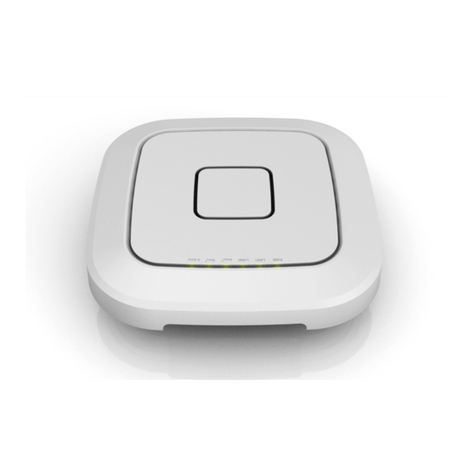
Everest AP1004WRi User manual

EVEREST™'Network'Solutions'
'
'
'
'
'
'
'
'
INSTALLATION'GUIDE'
'
AP1004WRi'Wireless'
Access'Point'
'
'
'
'
'
'
'
'
'
'
'
'
'
'
'
'
'
'
'
'
'
'
'
'
'
'
'
'
Model'Number:'AP24I612'

Release'Number:'1.4'
'
'

Page | i
AP1004WRe Installation Guide
Table of Contents
Chapter 1 : Overview ............................................................................................................. 1
Dependencies ................................................................................................................................ 1
AP1004WRi Package Contents .................................................................................................. 1
Additional Item ............................................................................................................................. 1
Item Identification ....................................................................................................................... 2
Related Documentation .............................................................................................................. 2
Chapter 2 : Installing AP1004WRi ..................................................................................... 3
Third-Party Mounting System Installation ........................................................................... 3
Connecting AP 1004WRi .............................................................................................................. 5
Chapter 3 : Configuring AP1004WRi ................................................................................. 6
Logging into BaseCamp ................................................................................................................ 6
Configuring AP 1004WRi .............................................................................................................. 6
Configuring AP1004WRi to Work with Discovery Protocol ................................................ 8
Chapter 4 : AP1004WRi Coverage ...................................................................................... 9
AP1004WRi Radiation Pattern .................................................................................................. 9
Regulatory Declarations .................................................................................................. 11
Appendix: Technical Specifications .............................................................................. 16
Mechanical Specifications ........................................................................................................16
Operational Requirements .......................................................................................................16
Environmental Requirements ..................................................................................................18

Page | ii
AP1004WRe Installation Guide
Safety Warnings
The AP1004WRi Wireless Access Point installation must be performed by certified technicians only and
in compliance with all local/state/federal safety requirements. All warnings and information in this
manual should be read and understood before proceeding with installation. Any noncompliance by the
user voids the warranty of the product.
General Safety
You can be killed or injured if performing antenna installation near electrical power lines.
Carefully read and follow all instructions in this guide. Ensure that there are no high voltage or
electrical fields nearby.
Working Aloft Warning
When working on tower or roof, individuals must wear safety belts. Tools must be tied to the
individual using them. Workers below must wear safety helmets.
Lightning Activity Warning
Make sure not to connect or disconnect cables during periods of lightning activity. A surge
protective device should be installed to prevent potential damage from very high surges, for
instance, the peak surges caused by lightning.
Explosive Device Proximity Warning
Do not operate network devices close to explosive merchandise or in explosive environments,
for example, in the vicinity of a gas station.
Antenna Placement Warning
Do not install any antenna near overhead power lines or other electric light, or where the
antenna can come into contact with such circuits.
Grounding Warning
Protect your AP1004WRi Wireless Access Point by installation of grounding lines. The ground
connection must be complete before connecting power to the AP1004WRi Wireless Access
Point
enclosure.
The
requirement
of
grounding
is
to
make
sure
the
resistance
is
less
than
5 ohm between the ground termination point to grounding tier.
Power Installation Warning
The installation of the power switch must be performed by a certified technician. The power
switch is not supplied with the AP1004WRi Wireless Access Point. The power cord must be
assembled by a certified technician, and the final assembly must comply with related
requirements.
Solar Irradiation and High Temperature Protection
Pay attention to the level of sunlight, which can increase the working temperature of the
AP1004WRi Wireless Access Point to higher than specifications allow.

Page | 1
AP1004WRe Installation Guide
Chapter 1 : Overview
This document provides information and procedures required to install and configure the AP1004WRi
Wireless Access Point (model number AP14E612) into a WLAN installation and is intended for certified
system installers, system administrators, and network operators.
The WLAN system is designed for high density deployments. It comprises of the following main
components:
•
AP1004WRi Wireless Access Point (AP)
•
Access Controller (AC)
•
BaseCamp™ Wireless Management System
Dependencies
The installation and configuration of AP1004WRi Wireless Access Point depends on the following
components:
•
Access Controller
•
BaseCamp™ Wireless Management System
•
DHCP Server
AP1004WRi Package Contents
The AP1004WRi package consists of the following item:
•
One AP1004WRi Wireless Access Point
Additional Item
The following additional item is to be purchased separately:
•
Access Controller
The BaseCamp™ Wireless Management System is bundled along with the Access Controller.
The installation technician is responsible for procuring wall/ceiling anchors, mounting
screws, and safety systems, as required by the local/state/federal authorities govern-
ing the installation of the AP1004WRi Wireless Access Point.

Page | 2
AP1004WRe Installation Guide
Item Identification
The following figures show top and bottom view of the AP1004WRi Wireless Access Point.
Figure 1: AP1004WRi Wireless Access Point - Top View
Figure 2: AP1004WRi Wireless Access Point - Bottom View
Related Documentation
•
AP1004WRe Installation Guide
•
AP1004NRe Installation Guide
•
AP1002We Installation Guide
•
AP1002Oi Installation Guide
•
Access Controller Installation Guide
•
BaseCamp™ Wireless LAN Management System User Guide
•
BaseCamp™ Wireless LAN Management System Quick Start Guide

Page | 3
AP1004WRe Installation Guide
Chapter 2 : Installing AP1004WRi
This section provides information required to install AP1004WRi Wireless Access Point.
Third-Party Mounting System Installation
AP1004WRi Wireless Access Point has two sets of mounting holes at the bottom of the chassis for
attaching third-party mounting systems:
•
The inner set of mounting holes are 75 mm apart in both the horizontal and vertical directions and are
tapped with a M4 x 0.7 mm thread pattern to a depth of 10 mm.
The AP1004WRi installation must be performed by certified technicians only and
in compliance with all local/state/federal safety requirements and building codes.
Proper grounding and surge protectors may be required in some installations.
The network coverage depends on the location and position of the AP1004WRi.
The installer or user assumes all liabilities unless the installation methods are explicitly
stated in a warranty agreement between Tembo Systems, Inc. and the third-party
installer.

Page | 4
AP1004WRe Installation Guide
•
The outer set of mounting holes are 100 mm apart in both the
horizontal and vertical directions and are tapped with a M6 x 1.0 mm
thread pattern to a depth of 10 mm.
Third-party systems must be capable of safely supporting the AP1004WRi Wireless
Access Point.
The exposed screw length (exclusive of mounting bracket thickness and any
washers or locking devices) cannot exceed 10 mm so as to avoid any damage to the
chassis.
Apply a drop of LocTite 243 threadlocker adhesive on each shoulder screw
before inserting into the chassis to prevent loosening, leakage, and corrosion.

Page | 5
AP1004WRe Installation Guide
Connecting AP 1004WRi
Perform this procedure to connect the AP1004WRi Wireless Access Point to the network.
1.
For Access Points powered from a Network Switch with PoE+ capabilities, Attach the two
cables directly to the Eth0 and ETH1 RJ45 receptacle on the back side of the AP1004WRi
Wireless Access Point chassis.
Locate Ethernet Ports Connect Primary Port Connect Secondary Port
2.
For Access Points powered from the optional AC/DC Adapter, Attach the Power Connector
first, then attach the Ethernet cables to the Eth0 and ETH1 RJ45 receptacle.
Connect Power Adapter Connect Primary Port Connect Secondary Port
3.
Connect the opposite ends of the Ethernet cables to a Ethernet Switch. If using Network
power, Verify the network power source (PSE) is configured to supply PoE+ power (30
Watts/Port) and supports 2-Event Classification, or the AC/DC Adapter is plugged into a AC
Source.
When injectors or mid-span are used, connect the access point to the “Data + Power” port
and the Ethernet Switch to the “Data” port of the injector or midspan.
4.
Verify the PoE+ source is providing power and the Ethernet switch port has established link with both
the ports. Note: Eth1 is normally disabled in the access point, so while it will link, no packets will be
transferred unless the access point is configured to support link aggregation.

Page | 6
AP1004WRe Installation Guide
Chapter 3 : Configuring AP1004WRi
This section provides information and procedures required to configure the AP1004WRi Wireless Access
Point.
Logging into BaseCamp
Perform this procedure to log into BaseCamp.
1.
Log into BaseCamp URL, https://<AC IP address> using the following credentials:
•
Username: [email protected]
•
Password: admin
Welcome to BaseCamp page is displayed.
Configuring AP 1004WRi
Perform this procedure to configure the AP1004WRi Wireless Access Point.
1.
Configure the POE+ ports of the L2/L3 switch as access ports with untagged PVID.
The PoE+ source must identify itself as PoE+ capable using the 2-event classification method. For more
information on configuring the AP1004WRi Wireless Access Points that are connected to
POE+ sources that support a discovery protocol, see Configuring AP1004WRi to Work With Discovery
Protocol.
2.
Connect the AP1004WRi Access Point to a POE+ source.
Once powered up, the AP1004WRi Access Point requests an IP address from the DHCP server. This
process may take up to 90 seconds.
3.
Verify if the AP1004WRi was assigned an IP address by doing one of the following:
•
Review the DHCP logs on the DHCP server
•
Log into BaseCamp to review the status in the Access Points page
Along with the IP address, the AP1004WRi receives the IP address of the Access Controller and
establishes a connection with it.

Page | 7
AP1004WRe Installation Guide
4.
The AP1004WRi is manufactured with a generic country code. During the discovery phase of the
AP1004WRi, the Access Controller verifies the country code of the AP1004WRi before allowing it to
join the network.
•
If the country code registered in the non-volatile memory of the AP1004WRi and the country code
locked into the Access Controller software match, the AP1004WRi is allowed to join the network.
•
If an AP1004WRi is detected with a generic country code, the Access Controller registers the
AP1004WRi by overwriting the generic country code with the locked country code from the
BaseCamp configuration. After updating the country code, the AP1004WRi is automatically
rebooted allowing it to join the network.
•
If the AP1004WRi is set with a different country code, the AP1004WRi is quarantined and not
allowed to join the network.
5.
The only mode of operation for the AP1004WRi is Indoor. The BaseCamp GUI restricts reconfigure the
mode of operation.
The transmitters on the radio modules in the AP1004WRi are disabled when the
country code is in generic state, or when the AP1004WRi is quarantined.

Page | 8
AP1004WRe Installation Guide
Configuring AP1004WRi to Work with Discovery Protocol
In some cases, a POE+ Ethernet switch requires a Discovery Protocol such as LLDP and CDP to request
additional power above the 15.4 W PoE PSE limit. In such cases, the POE+ PSE source must be configured
to override the Discovery Protocol and force the PoE+ PSE source to provide at least 22.5 W of PoE+
power.
Perform this procedure to configure the AP to work with Discovery Protocol.
1. In the BaseCamp Access Point menu, set the Passive POE selection to flag the AP1004WRi Wireless
Access Point to ignore the POE+ status.
The AP1004WRi Wireless Access Point automatically reboots when the new Passive POE selection is
saved. All the AP1004WRi hardware resources are available after rebooting the AP1004WRi.
Use extreme caution. This is a manual mode of operation. There is no action taken by
the AP1004WRi, if PoE+ power is interrupted. Even a single port losing PoE+ power
may result in an overload on the port.

Page | 9
AP1004WRe Installation Guide
Chapter 4 : AP1004WRi Coverage
This section provides information on deployment options for optimal coverage from the AP1004WRi
Wireless Access Point.
AP1004WRi Radiation Pattern
The AP1004WRi has a patented, fully-integrated,
software-adjustable antenna system with the
following characteristics: band-optimized, tightly-
controlled radiation patterns, polarization and pattern
diversity, as well as beam angle and shape
configurability. Band-optimized antennas enable
optimal radiation in the entire 5 GHz spectrum;
polarization and pattern diversity provide enhanced
MIMO and MU-MIMO operation; beam angle and
shape configurability enable direct energy to various
spatial sectors for radio coverage zone control and
interference management. These unique features
provide system designers and integrators unparalleled
flexibility in various deployment venues, maximizing
network capacity with fewer AP’s and faster install
times
The 1004WRi leverages the combined power of four radios,
one 2.4 GHz (3x3:3) and three 5 GHz radios (4x4:4) with four
spatial streams per radio, for a total of 15 parallel streams. In
addition, dual 2.5 Gbps Ethernet ports provide up to 5 Gbps of
wired backhaul. The 1004WRi also offers a BLE radio while the
2.4 GHz radio can be fully or partially repurposed for dual-band
intrusion detection and spectrum monitoring. The 1004WRi
features a patented design and system architecture enabling
concurrent quad-radio operation without impacting the
radio’s performance for best-in-class aggregate PHY
throughput of 5 Gbps. In addition, the patented design does
not compromise RF performance and radio coverage, making
the 1004WRi amenable to different deployment venues and
scenarios.
Figure 4a: AP1004WRi Radiation Patterns
Figure 4b: AP1004WRi Radiation Patterns

Page | 10
AP1004WRe Installation Guide
The following figure shows fixed and reconfigurable coverage options for AP1004WRi.
Figure 5: AP1004WRi Coverage Options

Page | 11
AP1004WRe Installation Guide
Regulatory Declarations
Federal Communication Commission Interference Statement
This equipment has been tested and found to comply with the limits for a Class B digital device, pursuant
to Part 15 of the FCC Rules. These limits are designed to provide reasonable protection against harmful
interference in a residential installation. This equipment generates, uses and can radiate radio frequency
energy and, if not installed and used in accordance with the instructions, may cause harmful interference
to radio communications. However, there is no guarantee that interference will not occur in a particular
installation. If this equipment does cause harmful interference to radio or television reception, which can
be determined by turning the equipment off and on, the user is encouraged to try to correct the
interference by one of the following measures:
•
Reorient or relocate the receiving antenna.
•
Increase the separation between the equipment and receiver.
•
Connect the equipment into an outlet on a circuit different from that to which the receiver is
connected.
•
Consult the dealer or an experienced radio/TV technician for help.
This device complies with Part 15 of the FCC Rules. Operation is subject to the following two conditions:
(1) This device may not cause harmful interference, and (2) this device must accept any interference
received, including interference that may cause undesired operation.
This device and its antenna(s) must not be co-located or operating in conjunction with any other antenna
or transmitter.
Important Note:
FCC Caution: Any changes or modifications not expressly approved by the party responsible for
compliance could void the user's authority to operate this equipment.
Important Note:
Country Code selection feature to be disabled for products marketed to the US/Canada.
Important Note:
For 2.4 GHz 802.11bgn products available in the US/Canada market, only channel 1~11 can be operated.
Selection of other channels is not possible.
Important Note:
The 802.11bgn/Scanning WiFi Radio Module/FCCID:2AGMRTRM989DB and 802.11ac WiFi Radio
Module/ FCCID:2AGMRTRM9995G are intended for OEM integrator only and are certified to be
compliant when installed into, but not limited to, an end product with model name, AP1004WRi and
model number, AP24I612.

Page | 12
AP1004WRe Installation Guide
The OEM integrator is still responsible for the FCC compliance requirement of the end product, which
integrates these modules.
Important Note:
FCC Radiation Exposure Statement:
This equipment complies with FCC radiation exposure limits set forth for an uncontrolled environment.
This equipment should be installed and operated with a minimum distance of 20 cm between the radiator
& your body.

Page | 13
AP1004WRe Installation Guide
IC Statement:
This device complies with Industry Canada license-exempt RSS standard(s). Operation is subject to the
following two conditions: (1) this device may not cause interference, and (2) this device must accept any
interference, including interference that may cause undesired operation of the device.
Le présent appareil est conforme aux CNR d'Industrie Canada applicables aux appareils radio exempts de
licence. L'exploitation est autorisée aux deux conditions suivantes: (1) l'appareil ne doit pas produire de
brouillage, et (2) l'utilisateur de l'appareil doit accepter tout brouillage radioélectrique subi, même si le
brouillage est susceptible d'en compromettre le fonctionnement.
These radio transmitters (802.11bgn/Scanning WiFi Radio Module/IC:21218-TRM989DB and 802.11ac
WiFi Radio Module/IC:21218-TRM9995G) have been approved by Industry Canada to operate with the
antenna types listed below with the maximum permissible gain indicated. Antenna types not included in
this list, having a gain greater than the maximum gain indicated for that type, are strictly prohibited for
use with this device.
Le présent émetteur radio (802.11bgn/Scanning WiFi Radio Module/IC:21218-TRM999DB and 802.11ac
WiFi Radio Module/IC:21218-TRM9995G) a été approuvé par Industrie Canada pour fonctionner avec les
types d'antenne énumérés ci-dessous et ayant un gain admissible maximal d'antenne. Les types
d'antenne non inclus dans cette liste, ou dont le gain est supérieur au gain maximal indiqué, sont
strictement interdits pour l'exploitation de l'émetteur.
PCA-000020-000-X;
2.4G/5G-UNII2c
Multi-Band Antenna
Panel .........................................
(Max
Gain
@2.4
GHz = -0.5
dBi)
(Max Gain @5 GHz B3 = 4.90 dBi)
PCA-000032-000-X/PCA-000024-XXX-X;
5G-UNII1-2a/5G-UNII3 Antenna System through 5G-UNII1/2a Switch Matrix
(Max Net 5 GHz B1 Gain = 3.05 dBi)
5G-UNII1-2a/5G-UNII3 Antenna System through 5G-UNII1/2a Switch Matrix
(Max Net 5 GHz B2 Gain = 3.55 dBi)
PCA-000032-000-X/PCA-000025-XXX-X;
5G-UNII1-2a/5G-UNII3 Antenna System through 5G-UNII3 Switch Matrix
(Max Net 5 GHz B4 Gain = 0.00 dBi)
Dynamic Frequency Selection (DFS) for devices operating in the bands 5250-5350 MHz, 5470-5600 MHz
and 5650-5725 MHz.
Sélection dynamique de fréquences (DFS) pour les dispositifs fonctionnant dans les bandes 5250-5350
MHz, 5470-5600 MHz et 5650-5725 MHz.

Page | 14
AP1004WRe Installation Guide
The maximum antenna gain permitted for devices in the bands 5250-5350 MHz and 5470-5725 MHz shall
be such that the equipment still complies with the e.i.r.p. limit.
le gain maximal d’antenne permis pour les dispositifs utilisant les bandes 5250-5350 MHz et
5470-5725 MHz doit se conformer à la limite de p.i.r.e.
The maximum antenna gain permitted for devices in the band 5725-5850 MHz shall be such that the
equipment still complies with the e.i.r.p. limits specified for point-to-point and non-point-to-point
operation as appropriate.
le gain maximal d’antenne permis (pour les dispositifs utilisant la bande 5725-5850 MHz) doit se
conformer à la limite de p.i.r.e. spécifiée pour l’exploitation point à point et non point à point, selon le cas."
Operation in the band 5150-5250 MHz is only for indoor use to reduce the potential for harmful
interference to co-channel mobile satellite systems.
La bande 5150-5250 MHz est réservés uniquement pour une utilisation à l'intérieur afin de réduire les
risques de brouillage préjudiciable aux systèmes de satellites mobiles utilisant les mêmes canaux.
Users are advised that high-power radars are allocated as primary users (i.e. priority users) of the bands
5250-5350 MHz and 5650-5850 MHz and that these radars could cause interference and/or damage to LE-
LAN devices.
Les utilisateurs être avisés que les utilisateurs de radars de haute puissance sont désignés utilisateurs
principaux (c.-à-d., qu’ils ont la priorité) pour les bandes 5250-5350 MHz et 5650-5850 MHz et que ces
radars pourraient causer du brouillage et/ou des dommages aux dispositifs LAN-EL.
Important Note:
IC Radiation Exposure Statement:
This equipment complies with IC RSS-102 radiation exposure limits set forth for an uncontrolled
environment. This equipment should be installed and operated with a minimum distance of 20 cm
between the radiator & your body.
Cet équipement est conforme aux limites d'exposition aux rayonnements IC établies pour un
environnement non contrôlé. Cet équipement doit être installé et utilisé avec un minimum de 20 cm de
distance entre la source de rayonnement et votre corps.
Important Note:
Modules
802.11bgn/Scanning
WiFi
Radio
Module/IC:21218-TRM989DB
and
802.11ac
WiFi
Radio
Module/
IC:21218-TRM9995G are intended for OEM integrator only and are certified to be
compliant when installed into, but not limited to, an end product with model name, AP1004WRi and
model number, AP14E612.
The OEM integrator is still responsible for the IC compliance requirement of the end product, which
integrates these modules.
Any changes or modifications not expressly approved by the manufacturer could void the user's authority
to operate this equipment.

Page | 15
AP1004WRe Installation Guide
Japan Statement:
5GHz band (W52 & W53): Indoor use only “
電波法により 5.15-5.35 GHz 帯は屋内使用に限ります ”
(5GHz band 5.15-5.35 GHz, indoor use only.)
VCCI Statement:

Page | 16
AP1004WRe Installation Guide
Appendix: Technical Specifications
This section provides technical specifications of the AP1004WRi Wireless Access Point.
Mechanical Specifications
The following table provides mechanical specifications of the AP1004WRi Wireless Access Point.
Table 1: Mechanical Specifications
Height
Width
Depth
Weight
261 mm
(10.3 inch)
261 mm
(10.3 inch)
84 mm
(3.3 inch)
3.4 kg
(7.5 lbs)
Operational Requirements
The following table provides operational requirements of the AP1004WRi Wireless Access Point.
Table 2: Operational Requirements
Condition
Input Power Requirement
Max Power Consumption
Max power
Consumption
42.5-57 Vdc, 0.941 A, 40 W
40 W Max (~136.20 BTUs/hr)
Per Port Power
(Max Available Input Power)
42.5-56 Vdc, 1.2 A, 51.0 W (4P-PoE+ source)
42.5-56 Vdc, 600 mA, 25.5 W (PoE+ source)
-
37-56 Vdc, 355 mA, 12.95 W (PoE source)
-
Optional DC Input
12Vdc, 3333 mA, 40 W
Operating Condition
Power Over Ethernet Limit1
AP Limit Worst Case
802.3at x 1 port1
Power Delivered over 2-Ethernet Pair
42.5 Vdc @ 588 mA (25 W)
48.0 Vdc @ 521 mA (25 W)
56.0 Vdc @ 466 mA (25 W)
42.5 Vdc @ 588 mA x
1
(25 W Max)
802.3bt x 1 Port
(Draft)
Power Delivered over 4-Ethernet Pair
42.5 Vdc @ 941 mA (40 W)
48.0 Vdc@ 833 mA (40.W)
56.0 Vdc @ 714 mA (40 W)
42.5 Vdc @ 471 mA x 2
(~40 W Max)
802.3at x 2 ports
Power Delivered over 4-Ethernet Pair
42.5 Vdc @ 471 mA (~20 W)
48.0 Vdc @ 833 mA (~20 W)
56.0 Vdc @ 714 mA (~20 W)
42.5
Vdc
@
471
mA x 2
(~40 W Max)
802.3bt x 2 port
Power Delivered over 8-Ethernet Pair
42.5 Vdc @ 232 mA (~10 W)
48.0 Vdc @ 208 mA (~10 W)
56.0 Vdc @ 179 mA (~10 W)
42.5 Vdc @ 235 mA x 4
(~40W Max)
This manual suits for next models
1
Table of contents
Other Everest Wireless Access Point manuals
Popular Wireless Access Point manuals by other brands
Aruba Networks
Aruba Networks AirMesh MST200 installation guide
Cisco
Cisco Aironet 1600 Series Deployment guide
D-Link
D-Link AirPlus DWL-900AP user manual
Apprion
Apprion IONizer 4000 Series Hardware installation guide
Edimax
Edimax WAP1750 Quick installation guide
Cisco
Cisco WAP200 - Small Business Wireless-G Access... Administration guide
